Beams: loads, section checks and lateral stability
A beam turns transverse loads into shear and bending, then carries them to its supports.
First analyse the loading; only then compare the resulting actions with resistances.
Sources: LectureNotes/Ch 3_Beam.pdf, pp.2–17, and the supplied Data File.
Read equilibrium and section properties first.
Lecture examples are included immediately after the relevant concepts.
Expand an example to read its complete diagram, working, exam answer and self-check here.
1. Identify what is restrained
Vertical bending can trigger sideways motion
A beam has enough local bending resistance. Check whether its compression flange can move sideways and twist.
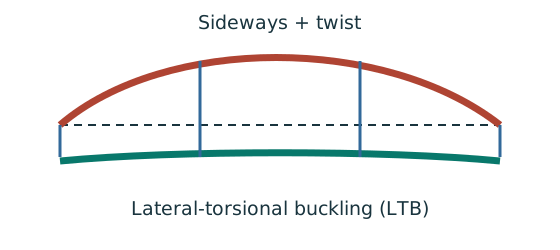
Prediction, then explanation. Adding a valid lateral restraint shortens a stability segment. It need not change the beam’s vertical reaction or moment diagram.
Identify the compressed flange and effective restraints. Calculate the specified slenderness, read buckling strength and compare resistance with the segment demand.
LE and ry use the same length unit. pb uses N/mm²; Sx uses mm³; Mb uses N·mm. mLT is dimensionless.
Scope. Use the specified section class, effective-length branch and loading condition. Load height alone does not prove a destabilizing case.
Check and takeaway. Removing a lateral restraint requires a new segment stability check. The old shorter-segment result cannot establish the longer segment’s adequacy.
Balance the isolated beam
Find the two vertical reactions before calculating internal shear or moment.
Prediction, then explanation. Move the same load toward B. Reaction B increases because the load has a larger moment arm about A.
Take moments about A. Reaction A has zero lever arm there. Then use vertical force balance to find reaction A.
P, RA and RB are forces in kN. L is support spacing and a is load position, both in m.
Scope. These expressions describe one point load on a simply supported beam. Add other loads through equilibrium; keep their actual positions.
Check and takeaway. Illustration: P = 60 kN, L = 6 m and a = 2 m give RB = 20 kN and RA = 40 kN.
Apply the reasoning to this section’s data and conditions
Physical interpretation: A support stops only certain movements
Holding a ruler up does not necessarily stop it sliding sideways or twisting.
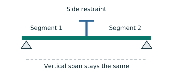
Sketch, not to scale; use the original dimensions.
- Identify vertical support, lateral restraint and torsional restraint separately.
- Find which flange is in compression in each region.
- Use only restraints actually provided by the question.
Remember: An extra side restraint does not create a new vertical reaction.
A vertical support stops vertical movement.
A lateral restraint stops sideways movement of the compression flange.
Torsional restraint prevents the cross-section twisting.
These are different conditions: a beam can stand on two supports yet buckle sideways between them.
In sagging bending the top flange is compressed; in hogging bending the bottom flange is compressed.
Follow the moment sign when identifying the flange requiring restraint.
The course accepts full lateral restraint when the restraint can resist of the maximum factored compression-flange force.
Concrete slabs can generally supply this in the stated lecture models.
If the question explicitly says “fully restrained”, carry out section, shear, local web and serviceability checks.
If restraint is only at discrete points, additionally check LTB over every segment.
A point load is not automatically a restraint.
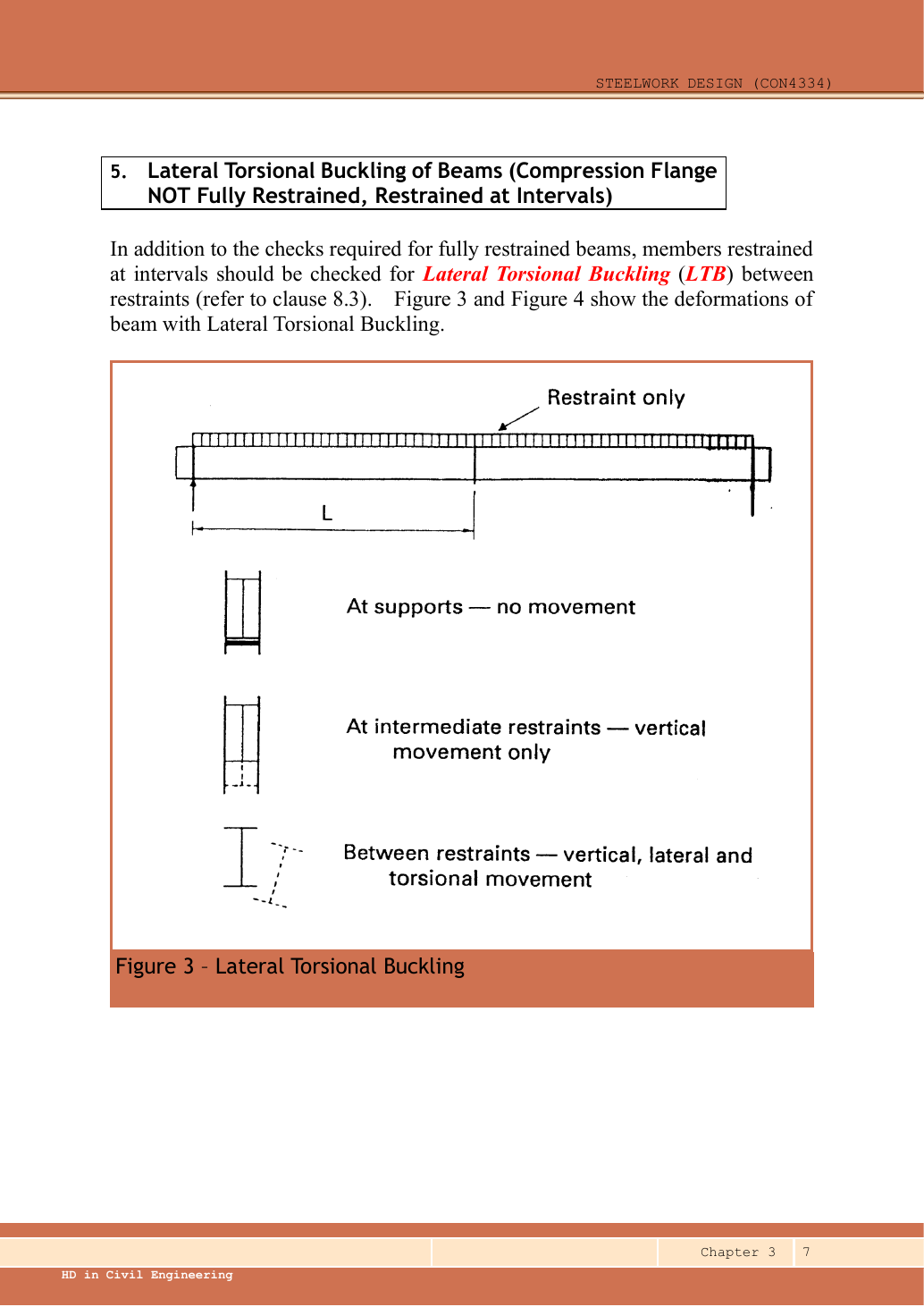
Original Ch 3 diagram: lateral movement and twist of a steel beam.
Read its restraint labels as follows: “Restraint only”; “At supports—no movement”; “At intermediate restraints—vertical movement only”; and “Between restraints—vertical, lateral and torsional movement”.
The label marks the spacing between restraints.Open full-size image
Prediction and explained answer.
A beam has lateral restraints at , , and .
Is it three independently simply supported vertical beams?
Answer and reasoning
No. Vertical bending analysis still uses the actual vertical supports.
The three lengths are the LTB segments; internal moments at the lateral restraints are generally nonzero.
Mechanism detailsA beam bends sideways and twists
The complete mechanism is explained below.
Read each stage together with its stated conditions; playback and interaction are not required.
- For the illustrated sagging beam the top flange is compressed.
- The unrestrained compression flange can move sideways while the complete cross-section twists.
Only effective restraints divide the member into unbraced segments.
They do not automatically add vertical supports.
Use the segment effective length, section properties and matching moment factor.
This is an exaggerated mode shape, not a calculated displacement.
2. Shear capacity and web slenderness
The web carries the shear check
Compare the applied shear with the resistance of the prescribed shear area.
Prediction, then explanation. At fixed design strength and depth, increasing web thickness increases this shear resistance.
Calculate the prescribed shear area. Multiply by the design shear stress from the course rule. Then compare matching force units.
D is overall depth; t is web thickness, in mm. Av uses mm². py uses N/mm², giving Vc in N.
Scope. Apply this area definition to the stated rolled section. Check web slenderness separately. The factor 0.6 is the low-shear threshold, not this resistance coefficient.
Check and takeaway. A shear pass alone does not prove bending, deflection or local support-web adequacy.
Apply the reasoning to this section’s data and conditions
Physical interpretation: What shear is trying to do
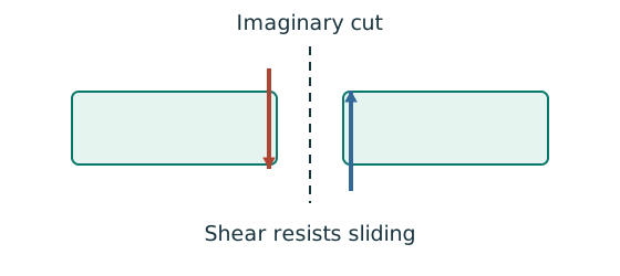
Imagine cutting the beam: shear stops the two cut faces sliding past each other.
Sketch, not to scale; use the original dimensions.
- Find the design shear from the load analysis.
- Use the section’s applicable shear area and strength.
- Compare demand with resistance in the same force units.
Remember: The web usually carries much of the vertical shear in an I-section.
| Section / load direction | Shear area |
|---|---|
| Rolled I, H or channel, load parallel to web | |
| Welded I, load parallel to web | |
| Rectangular hollow section | |
| T section | |
| Circular hollow section | |
| Solid rectangle | |
| Other section | , where is the relevant rectilinear element area |
is overall depth.
is clear web depth.
is web thickness.
is flange thickness.
Rolled and welded formulas differ.
For the rolled sections used in the worked beam examples, avoids a separate shear-web-buckling check, where .
This does not waive concentrated-load web bearing or web buckling.
Compare the largest absolute design shear with .
Mechanism detailsSee shear in the web
The complete mechanism is explained below.
Read each stage together with its stated conditions; playback and interaction are not required.
- Internal shear keeps the two sides of the cut in vertical equilibrium.
For the course’s common I-section case, the web provides the principal shear area.
Use the specified definition.
- A slender web may require a different shear-buckling route before a simple shear-resistance formula is used.
Use where applicable in the course.
Convert N to kN before comparing with design shear.
3. Bending capacity at low shear
Internal tension and compression resist moment
Find which section resistance applies before comparing it with the moment demand.
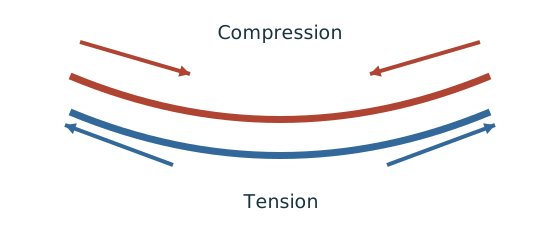
Prediction, then explanation. A larger appropriate section modulus raises resistance at fixed strength. Local plate buckling can restrict the usable modulus.
Classify the section first. At low shear, use the elastic expression for Class 3 or the prescribed capped plastic expression for Classes 1 and 2.
py uses N/mm². S is plastic modulus and Z is elastic modulus, both in mm³. Mc then uses N·mm.
Scope. This is section resistance, not whole-member LTB resistance. High shear and Class 4 require their appropriate treatment.
Check and takeaway. Selecting the larger of the two capped terms defeats the cap. Use their minimum.
Find which plate buckles first
Before using plastic bending resistance, check whether the flange and web can sustain the required stress distribution.
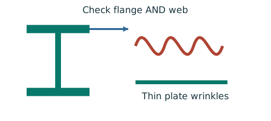
Prediction, then explanation. At fixed width, a thinner plate has a larger width-to-thickness ratio. Local buckling then becomes more restrictive.
Calculate the flange and web ratios separately. Compare each with the limits for its stress condition. The worse class governs.
py is the design yield strength in N/mm². ε is a dimensionless scale used in the supplied classification limits.
Scope. Pure bending and uniform compression use different web limits. Class 2 allows plastic resistance but not the Class 1 rotation capability.
Check and takeaway. A Class 1 web and Class 2 flange give a Class 2 section. Do not average the class numbers.
Apply the reasoning to this section’s data and conditions
Physical interpretation: Why one flange squeezes and the other stretches
Bending makes opposite sides of the section do opposite jobs.
Sketch, not to scale; use the original dimensions.
- Find the moment from the actual loads and supports.
- Choose the resistance formula allowed by the section class.
- Check whether the coexistent shear changes that formula.
Remember: Use shear at the location being checked, not an unrelated maximum.
Use the section class from flange and web limits.
Take the less favourable class.
At the location being checked, if , use the low-shear resistance below.
is plastic modulus, elastic modulus.
Properties in multiply by to become ; in divides by for .
| Class | Low-shear moment resistance |
|---|---|
| 1 plastic or 2 compact | |
| 3 semi-compact | pᵧZ, or pᵧSₑff where the permitted effective plastic property is established |
| 4 slender | pᵧZₑff or pᵧᵣZ, using an established effective property/reduced strength |
The ceiling limits working-load plasticity in this course method.
Check .
Never replace by the reduced equivalent LTB moment here: the cross-section sees the actual moment.
An unknown Class 4 effective modulus is missing design data, not permission to use gross .
Mechanism detailsCompression and tension across a section
The complete mechanism is explained below.
Read each stage together with its stated conditions; playback and interaction are not required.
- For sagging, the top flange is in compression and the bottom in tension; hogging reverses this.
- Elastic bending stress varies with distance from the neutral axis: .
- The section class governs whether elastic, plastic or effective properties may be used.
Use the shear at the section under examination.
The largest shear elsewhere is not automatically coexistent.
4. What changes when shear is high?
Shear and bending share the web
Decide whether the unreduced bending resistance remains applicable at the section being checked.
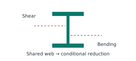
Prediction, then explanation. Raising shear beyond the specified threshold can reduce available bending resistance. A distant maximum shear is not the coexistent shear.
Find the moment-check position. Evaluate the shear there. Compare it with the low-shear threshold before selecting the resistance expression.
V is shear at the checked section; Vc is its shear resistance. Both use the same force unit.
Scope. Above the threshold, use the supplied reduction expression. The threshold itself is not a substitute resistance formula.
Check and takeaway. If the maximum shear anywhere is below the threshold, all sections satisfy that low-shear condition. Otherwise check the actual positions.
Apply the reasoning to this section’s data and conditions
Physical interpretation: The web is doing two jobs
Heavy shear leaves less of the web’s strength available for bending.
Sketch, not to scale; use the original dimensions.
- Check the course trigger using the coexistent shear.
- If triggered, use the appropriate reduced bending expression.
- Recheck moment demand against the reduced resistance.
Remember: The reduction is conditional.
Do not apply it to every beam.
Apply this branch only when the coexistent shear exceeds .
is the plastic modulus of the shear area about the bending axis, not the whole section .
For a rectangular shear area of breadth and depth , derive .
Establish the appropriate shear area before calculating it.
If , the shear check already fails.
The lecture examples have low shear.
However, this branch explains what to change in an unfamiliar heavily loaded variant.
Prediction and explained answer.
.
What is ?
Answer and reasoning
.
Reduce the bending contribution associated with the shear area.
Do not reduce the entire section capacity by .
Mechanism detailsHigh shear reduces bending resistance
The complete mechanism is explained below.
Read each stage together with its stated conditions; playback and interaction are not required.
- Part of the web contributes to bending while also carrying shear.
The course low-shear route applies at .
Above it, follow the applicable reduction expression.
- The highlighted web contribution is reduced, not the complete cross-section by an arbitrary percentage.
- Retain the section-class-specific formula and all bounds shown in the original calculation.
Mechanism detailsHigh shear reduces bending resistance
The complete mechanism is explained below.
Read each stage together with its stated conditions; playback and interaction are not required.
- Part of the web contributes to bending while also carrying shear.
The course low-shear route applies at .
Above it, follow the applicable reduction expression.
- The highlighted web contribution is reduced, not the complete cross-section by an arbitrary percentage.
- Retain the section-class-specific formula and all bounds shown in the original calculation.
5. A concentrated force can crush the web locally
A concentrated force spreads into the web
Check local web resistance at a support or concentrated load, even if overall beam strength passes.
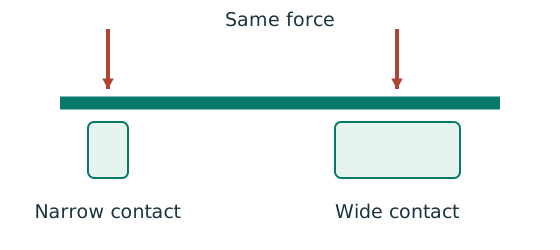
Prediction, then explanation. A longer valid stiff-bearing length can spread the same force over more web. A flexible contact is not automatically stiff bearing.
Match the actual bearing geometry to its source sketch. Use that sketch’s dimensions and permitted spread to calculate the resisting region.
b₁ is stiff-bearing length in mm. Web thickness and applicable design strength enter the prescribed local resistance equation.
Scope. End and interior cases can differ. A lateral-restraint symbol does not provide a bearing length or a load-introduction detail.
Check and takeaway. If bearing geometry is missing, give the applicable symbolic check and state the missing input. Do not borrow another example’s dimensions.
Apply the reasoning to this section’s data and conditions
Physical interpretation: A concentrated force can hurt one small region
A narrow contact presses much harder locally than the same force spread over a wider contact.
Sketch, not to scale; use the original dimensions.
- Find the actual stiff bearing length and end position.
- Check local crushing and local web buckling separately.
- Use the restraint conditions required by each expression.
Remember: Missing contact dimensions cannot be guessed from drawing scale.
The reaction or point load spreads through the flange before entering the web.
The stiff bearing length is the portion of the bearing that cannot appreciably bend.
It is not automatically the whole support plate width.
The source sketches show how load disperses through solid parts.
Read the applicable sketch and its dimensions, or use explicitly supplied by the problem.
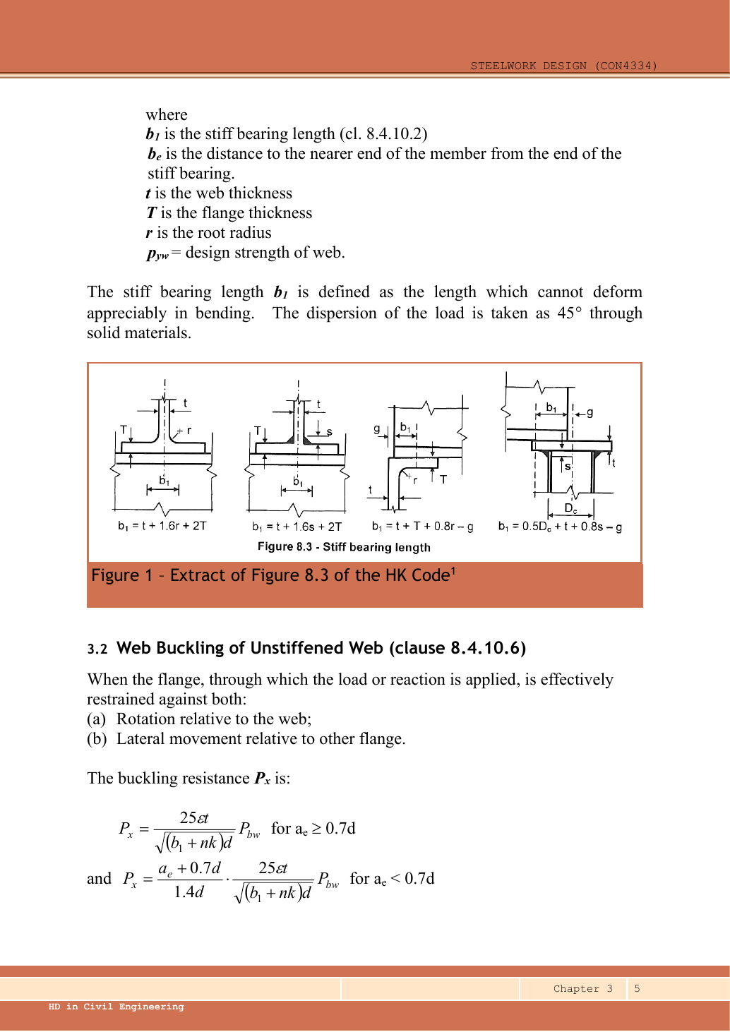
Ch 3 p.5: four alternative stiff-bearing geometries.
Each formula belongs to its own sketch.
Selectable formulas in left-to-right source order:Legend: , , , , and are located by the dimension arrows in each individual sketch.
Do not borrow a dimension from another sketch.
The source assumes a spread through solid material at and defines as the bearing length that cannot deform appreciably in bending (clause 8.4.10.2).
The web-buckling formula at the bottom of the source page is typeset in the next section of this lesson.Open full-size image
is the root radius.
is the distance from the near edge of the bearing to the member end.
is the design strength of the web at its actual thickness.
All lengths in give in .
Compare with the factored concentrated load or reaction at this location.
Missing or prevents an unconditional numerical bearing result.
Mechanism detailsSpread a concentrated force into the web
The complete mechanism is explained below.
Read each stage together with its stated conditions; playback and interaction are not required.
- A concentrated reaction first enters through the bearing/contact region.
- The flange and root geometry spread the force before it enters the web.
- A wider effective bearing region can reduce local stress for the same force.
End distance, stiff bearing length and restraint conditions must come from the original question.
The illustrated dimensions explain the mechanism.
They do not replace the original question data.
6. The web can buckle as a short compression member
The loaded web can act as a short strut
A concentrated load can buckle the web instead of crushing it. This requires a separate local check.
Prediction, then explanation. Reduced local restraint can increase the relevant effective length and reduce local buckling resistance.
First calculate the source model’s effective strip and base resistance. Then apply the branch required by local restraint and load position.
Local web effective length is not the beam span or the LTB segment length. Use the symbol definition in the selected local formula.
Scope. The short-strut picture explains a mechanism; it is not a derivation of every coefficient in the supplied web rule.
Check and takeaway. A local bearing pass does not establish a local buckling pass. State both conclusions and any unresolved restraint condition.
Apply the reasoning to this section’s data and conditions
Physical interpretation: What to do when one input is missing
A calculator cannot supply a dimension that the drawing never gave.
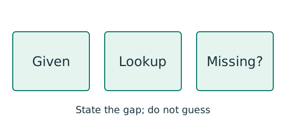
Sketch, not to scale; use the original dimensions.
- Separate given values, table values and calculated values.
- Complete the checks whose required inputs are available.
- State the missing input beside the remaining conditional result.
Remember: An illustrative assumption must not become an unstated exam given.
First establish whether the loaded flange is restrained against rotation relative to the web and lateral movement relative to the other flange.
The following applies when both conditions hold.
is the distance of the load/reaction line from the nearer member end.
It differs from , measured from the bearing edge.
Both multipliers are dimensionless.
is the effective length of the web as a compression member, not the beam’s lateral unbraced length.
The lecture does not give a universal value for every unrestrained web geometry.
Establish the restraint model and effective length before using the reduction.
Compare resistance with the same concentrated force used for bearing.
A good shear-capacity result does not prove this check.
Prediction and explained answer.
is centred on a bearing that starts at the member end.
What are and ?
Answer and reasoning
; .
The first is measured to the bearing edge, the second to the centred reaction line.
Mechanism detailsThe web behaves like a short strut
The complete mechanism is explained below.
Read each stage together with its stated conditions; playback and interaction are not required.
- A concentrated force compresses a local region between the flanges.
- The thin web can buckle sideways before local crushing governs.
- The source distinguishes restraint against rotation and relative lateral movement.
Web bearing and web buckling are separate checks.
Select the original expression whose assumptions are satisfied.
Mechanism detailsThe web behaves like a short strut
The complete mechanism is explained below.
Read each stage together with its stated conditions; playback and interaction are not required.
- A concentrated force compresses a local region between the flanges.
- The thin web can buckle sideways before local crushing governs.
- The source distinguishes restraint against rotation and relative lateral movement.
Web bearing and web buckling are separate checks.
Select the original expression whose assumptions are satisfied.
7. Select and check a fully restrained beam
Follow one strip of floor
An area load must become a beam load before beam reactions can be calculated.
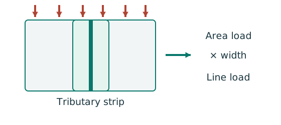
Prediction, then explanation. At fixed area load, twice the tributary width gives twice the line load. An end reaction remains a concentrated force.
Consider one metre along the beam. The associated floor area is b square metres. Multiply area load by that width.
q is area load in kN/m²; b is tributary width in m; w is line load in kN/m.
Scope. Determine b from slab spanning and supports. Add beam self-weight separately. A secondary-beam reaction is not automatically a UDL.
Check and takeaway. Illustration: . The width cancels one length unit.
Keep load categories separate
A floor carries permanent material and changing occupancy loads. Find the design load for the stated check.
Prediction, then explanation. Increasing imposed load changes its own term. It does not change the dead-load factor or the steel stiffness.
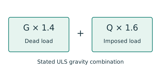
First convert mass to weight where required. Next collect G and Q in compatible units. Apply the combination specified by the course problem.
G is characteristic dead load; Q is characteristic imposed load. Wu is the design load for this course gravity combination.
Scope. This combination is not universal. Use the specified service load for deflection and the stated factors for other standards or cases.
Check and takeaway. Illustration: G = 10 kN and Q = 5 kN give 22 kN. Factoring their sum by one guessed factor loses the distinction.
Use the same mechanism: Balance the isolated beam. Move the same load toward B. Reaction B increases because the load has a larger moment arm about A.
Apply the reasoning to this section’s data and conditions
Physical interpretation: How a floor load reaches a beam
Each beam collects the load from its own strip of floor.
Sketch, not to scale; use the original dimensions.
- Find the tributary width from the actual plan.
- Area load × tributary width gives load per beam length.
- A supporting beam receives the other beam’s end reaction.
Remember: A reaction becomes a point load, not automatically a UDL.
Physical interpretation: How much does the beam sag?
Strength asks whether it fails; deflection asks how far it moves.
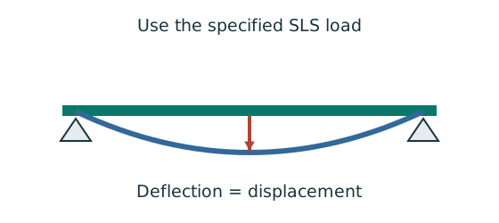
Sketch, not to scale; use the original dimensions.
- Use the serviceability load case specified by the course question.
- Choose the expression matching the support and load positions.
- Use consistent units for load, length, E and I.
Remember: The largest deflection is not always at midspan.
Draw the load path.
Convert slab pressure () using tributary width (): ().
Transfer supporting-beam reactions as point loads.
Keep characteristic dead and imposed loads separate.
Include beam self-weight once, using mass×gravity/1,000, unless already included.
Use the stated ultimate factors; derive reactions, shear and bending from equilibrium.
Locate maxima at load jumps or where .
Estimate Srequired=M/pᵧ, assuming a thickness band only for the first trial.
Select an actual section-table row; recheck pᵧ with its flange thickness.
Classify flange and web.
Check shear, coexistent-shear bending, and requested local bearing/buckling.
Use the specified serviceability load combination and limit to check deflection.
If a check fails, change section and repeat dependent checks.
For these lecture examples the deflection load is the unfactored imposed load, , and brittle-finish limit .
The finish condition in Examples 1 and 2 is explicitly an assumption in the lecturer’s solution.
Other conditions need their stated limit.
Use , and throughout: , .
These two formulas are not valid unchanged for off-centre loads, cantilevers or continuous beams.
See Example 3 for an off-centre-load derivation.
Beam example 1: fully restrained beam, from loads to deflection
Open this example on its own page
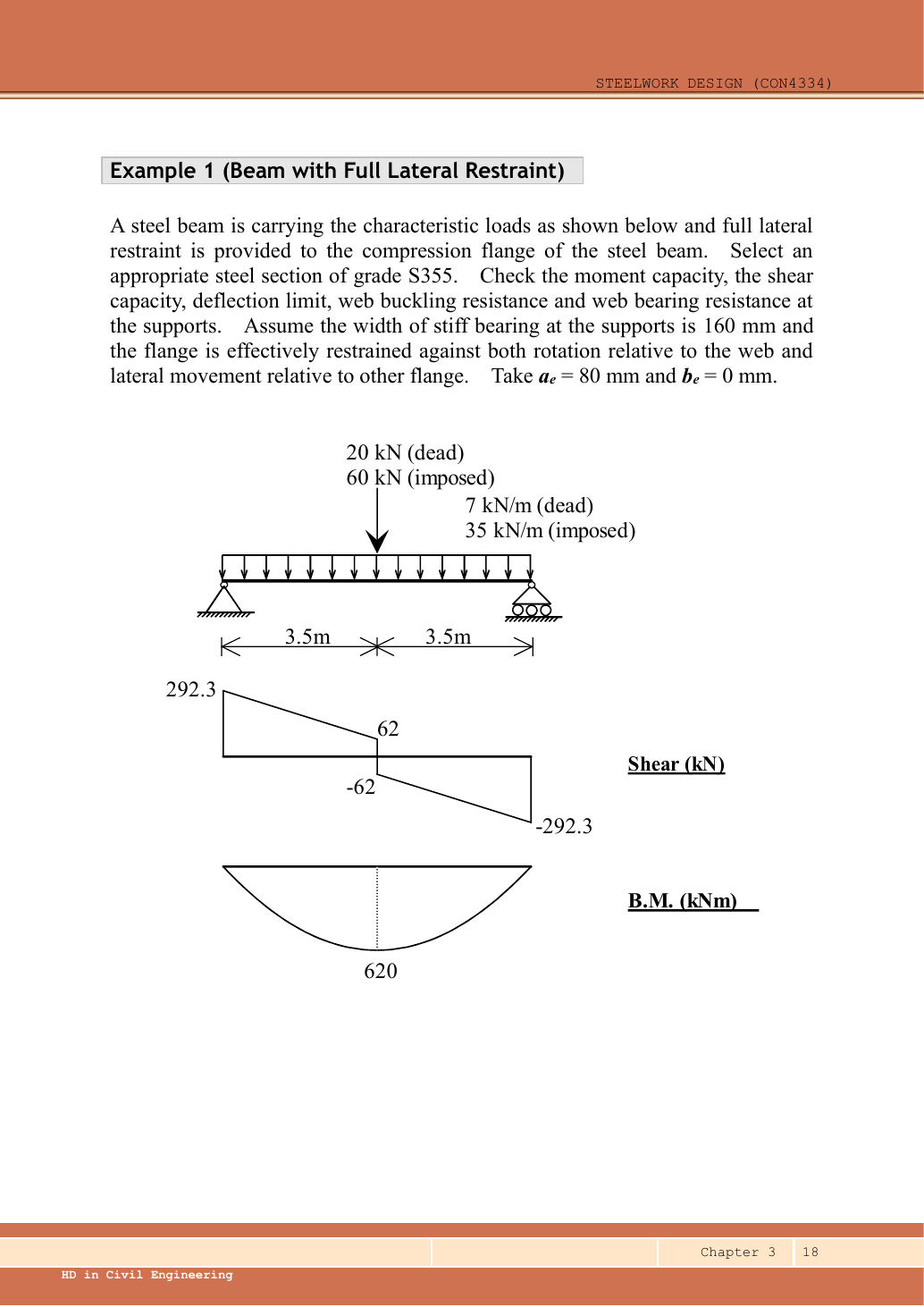
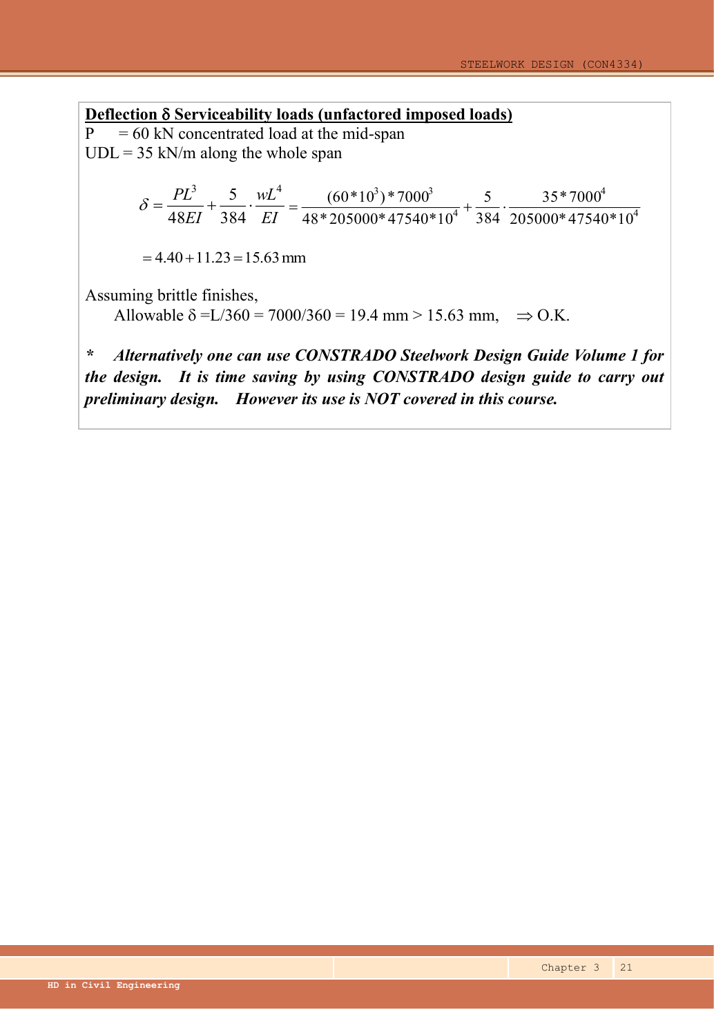
Select a Grade S355 section for a fully laterally restrained, simply supported beam. Check shear, bending, support web bearing, support web buckling and deflection. The central loads are dead and imposed; full-span UDLs are dead and imposed.
Original source: LectureNotes/Ch 3_Beam.pdf — p. 18, p. 19, p. 20, p. 21.
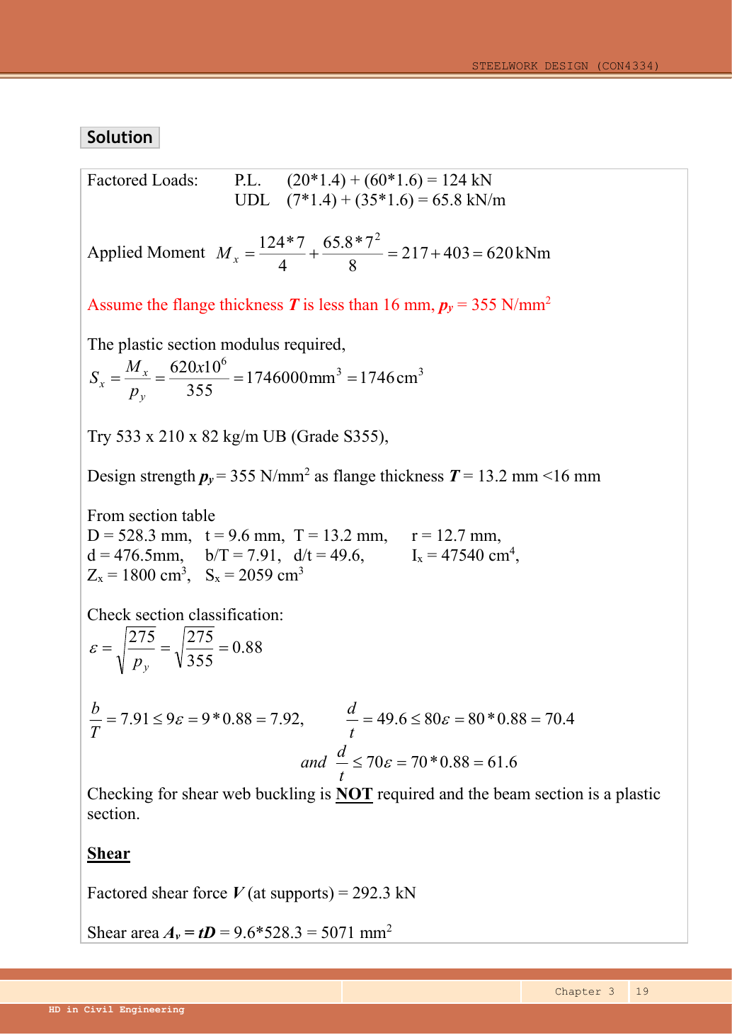
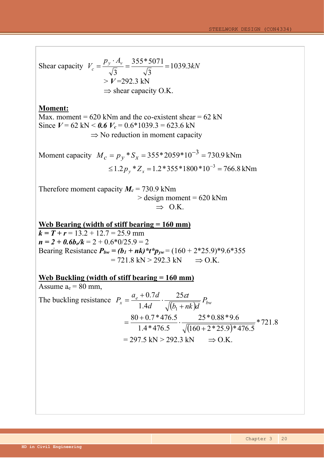
A given value comes from the question or diagram.
A lookup value comes from the named table.
A calculated value follows from the working.
Each assumption is stated where the calculation needs it.
Known information, diagram labels and unknowns
A safe beam can still sag too far
Check whether the beam displacement exceeds the permitted service limit.
Prediction, then explanation. For the same UDL and stiffness, doubling span multiplies deflection by sixteen. Doubling I halves deflection.
Load bends each beam segment. The curvature accumulates along the span. Material stiffness E and geometric stiffness I resist that deformation.
Use w in N/mm, L in mm, E in N/mm² and I in mm⁴. The resulting midspan deflection is in mm.
Scope. The formula assumes a prismatic, simply supported, linear-elastic beam with full-span UDL. Use the stated service load and deflection limit.
Check and takeaway. A higher yield grade does not automatically increase E. Passing a strength check therefore does not prove acceptable deflection.
Use the same mechanism: Vertical bending can trigger sideways motion. Adding a valid lateral restraint shortens a stability segment. It need not change the beam’s vertical reaction or moment diagram.
Use the same mechanism: Keep load categories separate. Increasing imposed load changes its own term. It does not change the dead-load factor or the steel stiffness.
Apply the reasoning to this section’s data and conditions
| Quantity | Given, lookup or assumption |
|---|---|
| Span and loading | Given in the upper drawing: , one central point load and two full-span UDL components. |
| Bearing | Given in the question: , , . Loaded flange is restrained against both specified local movements. |
| Lateral restraint | Given: compression flange fully restrained, so no member LTB check is needed. |
| Deflection | Lecturer assumes brittle finishes and uses unfactored imposed loads only; limit . . |
| Section properties | Lookup Data File pp.9–10, row UB. Original solution also lists the values on p.19. |
Why this method applies
Use the same mechanism: Vertical bending can trigger sideways motion. Adding a valid lateral restraint shortens a stability segment. It need not change the beam’s vertical reaction or moment diagram.
Use the same mechanism: Balance the isolated beam. Move the same load toward B. Reaction B increases because the load has a larger moment arm about A.
A table value has conditions
Find a design property without mixing a row, column or standard from a different case.
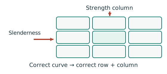
Prediction, then explanation. A different flange thickness can select a lower design strength even when the steel grade name remains unchanged.
Match the complete section designation. Read the relevant axis and unit. For strength tables, select material, thickness and curve before interpolating.
Given values come from the question. Lookup values come from a named table. Assumed values require an explicit condition.
Scope. A missing row or omitted restraint cannot be recovered from a schematic’s scale. Keep the result conditional when required data are absent.
Check and takeaway. Record the table, row, column and unit beside the substitution. That makes a later check possible.
Apply the reasoning to this section’s data and conditions
First distinguish applied load from internal action.
A load acts on the beam.
Shear and moment are internal actions needed to carry it.
Symmetry makes the two reactions equal.
The shear changes sign at the central point load.
Therefore, that is the maximum-moment position.
Full lateral restraint removes LTB from this example, but does not remove local web checks.
Select a trial section from its plastic modulus, then verify every other requirement.
1. Factor each load component
Use the same mechanism: Keep load categories separate. Increasing imposed load changes its own term. It does not change the dead-load factor or the steel stiffness.
Use the same mechanism: A safe beam can still sag too far. For the same UDL and stiffness, doubling span multiplies deflection by sixteen. Doubling I halves deflection.
Apply the reasoning to this section’s data and conditions
Physical interpretation: How a floor load reaches a beam
Each beam collects the load from its own strip of floor.
Sketch, not to scale; use the original dimensions.
- Find the tributary width from the actual plan.
- Area load × tributary width gives load per beam length.
- A supporting beam receives the other beam’s end reaction.
Remember: A reaction becomes a point load, not automatically a UDL.
The given dead UDL is the prescribed design input.
Do not add an extra assumed self-weight on top of it.
Keep the unfactored imposed loads and for the separate deflection calculation.
Mechanism detailsFrom characteristic to design load
The complete mechanism is explained below.
Read each stage together with its stated conditions; playback and interaction are not required.
G is permanent load; Q is imposed load.
A surface load and a line load also have different units.
This illustration uses the course gravity case .
Other combinations in the original text retain their own factors.
- For illustrative , the separate load contributions show what changes when Q increases.
Do not carry this ULS total automatically into deflection.
Follow the stated SLS load case.
2. Reactions, shear and maximum moment
Use the same mechanism: Balance the isolated beam. Move the same load toward B. Reaction B increases because the load has a larger moment arm about A.
A cut reveals the internal actions
Find where the beam moment is largest. A large load arrow alone does not locate that point.
Prediction, then explanation. Under a uniform downward load, shear falls steadily. Moment reaches a stationary value where shear becomes zero.
Balance the forces on the cut piece to get V. Balance their moments about the cut to get M. Evaluate each load region separately.
x and L use m; w uses kN/m; V uses kN; M uses kN·m. These lines apply before any point load.
Scope. A point load adds a shear jump. A concentrated couple adds a moment jump. Check load points, supports and overhang roots too.
Check and takeaway. A UDL gives a sloping shear line and a curved moment line. A flat moment diagram therefore cannot represent a loaded UDL region.
Apply the reasoning to this section’s data and conditions
Equivalently .
The source labels after rounding.
UDL makes shear linear and bending parabolic.
The point load makes a shear jump of but no moment jump.
Mechanism detailsBalance reactions and moments
The complete mechanism is explained below.
Read each stage together with its stated conditions; playback and interaction are not required.
This demonstrator is a simply supported 6 m beam with a 60 kN point load.
It is not the page’s original loading diagram.
.
Moving the load towards B increases .
.
The two upward reactions must sum to P.
With the load at midspan, .
End couples, UDLs and overhangs require their own equilibrium terms.
3. Select a trial section and read the correct columns
Use the same mechanism: A table value has conditions. A different flange thickness can select a lower design strength even when the steel grade name remains unchanged.
Apply the reasoning to this section’s data and conditions
| Table column | Selected-row value |
|---|---|
| ; web ; flange ; root ; clear web () | |
| Flange ; web | |
| Major-axis ; elastic ; plastic |
and are nominal section designations, not the exact and flange width.
The table’s confirms the initial assumption.
Select the major-axis columns because the vertical load bends the beam about .
This is the lecturer’s suitable trial section, not a demonstrated minimum-mass optimum.
Mechanism detailsRead a table without losing the keys
The complete mechanism is explained below.
Read each stage together with its stated conditions; playback and interaction are not required.
- Name the required property: material strength, section property, buckling strength or a moment factor.
- Keep section size, steel grade, thickness band, curve and axis as separate lookup keys.
, and require different conversion powers.
Do not use adjacent columns interchangeably.
Use bracketing rows within the same valid column.
The original page remains the source of all table values.
4. Establish the section class and web-shear branch
Use the same mechanism: Find which plate buckles first. At fixed width, a thinner plate has a larger width-to-thickness ratio. Local buckling then becomes more restrictive.
Use the same mechanism: The web carries the shear check. At fixed design strength and depth, increasing web thickness increases this shear resistance.
Apply the reasoning to this section’s data and conditions
Physical interpretation: A thin part can wrinkle first
A thin plate may wrinkle before the whole steel member reaches its intended resistance.
Sketch, not to scale; use the original dimensions.
- Check flange and web slenderness using their own definitions.
- Compare each ratio with the correct class limits.
- The element with the more restrictive class determines the section class.
Remember: Bending limits and uniform-compression limits are different.
The flange classification is close to its limit: use the table ratio and keep enough precision.
The web’s bending-class limit and shear-buckling threshold are different tests.
A separate shear-web-buckling calculation is not required; concentrated reaction web buckling is still checked below.
Mechanism detailsWhy thin elements buckle locally
The complete mechanism is explained below.
Read each stage together with its stated conditions; playback and interaction are not required.
- The flange outstand and web have different widths, thicknesses and edge support conditions.
- A thinner plate can wrinkle locally before the complete member loses stability.
Class 1 allows plastic rotation.
Class 2 reaches plastic resistance.
Class 3 reaches elastic resistance.
Class 4 requires effective properties.
Check every relevant compression element with the supplied limits and stress distribution.
The deformation shown is qualitative.
5. Resist the largest shear
Use the same mechanism: The web carries the shear check. At fixed design strength and depth, increasing web thickness increases this shear resistance.
Apply the reasoning to this section’s data and conditions
Mechanism detailsSee shear in the web
The complete mechanism is explained below.
Read each stage together with its stated conditions; playback and interaction are not required.
- Internal shear keeps the two sides of the cut in vertical equilibrium.
For the course’s common I-section case, the web provides the principal shear area.
Use the specified definition.
- A slender web may require a different shear-buckling route before a simple shear-resistance formula is used.
Use where applicable in the course.
Convert N to kN before comparing with design shear.
6. Check coexistent shear, then bending
Use the same mechanism: Internal tension and compression resist moment. A larger appropriate section modulus raises resistance at fixed strength. Local plate buckling can restrict the usable modulus.
Use the same mechanism: Shear and bending share the web. Raising shear beyond the specified threshold can reduce available bending resistance. A distant maximum shear is not the coexistent shear.
Apply the reasoning to this section’s data and conditions
The largest shear actually also lies below , so every section is low-shear here.
Do not use the larger of the two moment resistances: the second is a ceiling.
Mechanism detailsCompression and tension across a section
The complete mechanism is explained below.
Read each stage together with its stated conditions; playback and interaction are not required.
- For sagging, the top flange is in compression and the bottom in tension; hogging reverses this.
- Elastic bending stress varies with distance from the neutral axis: .
- The section class governs whether elastic, plastic or effective properties may be used.
Use the shear at the section under examination.
The largest shear elsewhere is not automatically coexistent.
7. Support web bearing
Use the same mechanism: A concentrated force spreads into the web. A longer valid stiff-bearing length can spread the same force over more web. A flexible contact is not automatically stiff bearing.
Apply the reasoning to this section’s data and conditions
Physical interpretation: A concentrated force can hurt one small region
A narrow contact presses much harder locally than the same force spread over a wider contact.
Sketch, not to scale; use the original dimensions.
- Find the actual stiff bearing length and end position.
- Check local crushing and local web buckling separately.
- Use the restraint conditions required by each expression.
Remember: Missing contact dimensions cannot be guessed from drawing scale.
Web thickness also gives .
This is an end bearing, hence with ; using the interior value would artificially increase resistance.
Mechanism detailsSpread a concentrated force into the web
The complete mechanism is explained below.
Read each stage together with its stated conditions; playback and interaction are not required.
- A concentrated reaction first enters through the bearing/contact region.
- The flange and root geometry spread the force before it enters the web.
- A wider effective bearing region can reduce local stress for the same force.
End distance, stiff bearing length and restraint conditions must come from the original question.
The illustrated dimensions explain the mechanism.
They do not replace the original question data.
8. Support web buckling
Use the same mechanism: The loaded web can act as a short strut. Reduced local restraint can increase the relevant effective length and reduce local buckling resistance.
Apply the reasoning to this section’s data and conditions
Both local flange restraints are explicitly given, so no reduction is needed.
The reaction uses of this resistance: support web buckling is the tightest strength check.
Keep the given and distinct.
Mechanism detailsThe web behaves like a short strut
The complete mechanism is explained below.
Read each stage together with its stated conditions; playback and interaction are not required.
- A concentrated force compresses a local region between the flanges.
- The thin web can buckle sideways before local crushing governs.
- The source distinguishes restraint against rotation and relative lateral movement.
Web bearing and web buckling are separate checks.
Select the original expression whose assumptions are satisfied.
9. Deflection under the specified serviceability case
Use the same mechanism: A safe beam can still sag too far. For the same UDL and stiffness, doubling span multiplies deflection by sixteen. Doubling I halves deflection.
Apply the reasoning to this section’s data and conditions
Physical interpretation: How much does the beam sag?
Strength asks whether it fails; deflection asks how far it moves.
Sketch, not to scale; use the original dimensions.
- Use the serviceability load case specified by the course question.
- Choose the expression matching the support and load positions.
- Use consistent units for load, length, E and I.
Remember: The largest deflection is not always at midspan.
Symmetry puts the maximum at midspan for both components, so adding these two maximum values is valid.
The selected UB passes all requested checks under the stated model.
Mechanism detailsSee stiffness and deflection
The complete mechanism is explained below.
Read each stage together with its stated conditions; playback and interaction are not required.
Use the specified SLS load, span and support arrangement.
The demonstrator has a full-span UDL.
The loaded beam bends.
The deformation is exaggerated so its shape can be seen.
For a simply supported full-span UDL, .
Double L with w, E and I unchanged: δ becomes 16 times as large.
The readout uses , and .
Select the finish/support-specific limit from the original table.
Result and concise exam wording
Use the same mechanism: The loaded web can act as a short strut. Reduced local restraint can increase the relevant effective length and reduce local buckling resistance.
Apply the reasoning to this section’s data and conditions
Use S355 UB, Class 1.
Ultimate , , , .
.
.
; .
Imposed-load .
Adequate; support web buckling is the closest strength check.
Misconceptions and checks
Use the same mechanism: The loaded web can act as a short strut. Reduced local restraint can increase the relevant effective length and reduce local buckling resistance.
Use the same mechanism: A safe beam can still sag too far. For the same UDL and stiffness, doubling span multiplies deflection by sixteen. Doubling I halves deflection.
Use the same mechanism: Vertical bending can trigger sideways motion. Adding a valid lateral restraint shortens a stability segment. It need not change the beam’s vertical reaction or moment diagram.
Apply the reasoning to this section’s data and conditions
- Do not factor imposed loads again in the prescribed deflection check.
- Use actual table dimensions, not as .
- Compare against the smaller moment-capacity expression.
- Do not confuse shear-web slenderness with concentrated-load web buckling.
How the method transfers to a new variant
Use the same mechanism: Find which plate buckles first. At fixed width, a thinner plate has a larger width-to-thickness ratio. Local buckling then becomes more restrictive.
Use the same mechanism: A safe beam can still sag too far. For the same UDL and stiffness, doubling span multiplies deflection by sixteen. Doubling I halves deflection.
Use the same mechanism: Vertical bending can trigger sideways motion. Adding a valid lateral restraint shortens a stability segment. It need not change the beam’s vertical reaction or moment diagram.
Apply the reasoning to this section’s data and conditions
- Identify the vertical supports, span, lateral restraints and individual load positions.
- Keep dead and imposed loads separate; form the required ultimate and serviceability cases.
- Find reactions and the maximum shear/moment by equilibrium, with units.
- Choose a section-table row, confirm thickness-dependent strength, and classify both flange and web.
Check shear and bending.
Add segment LTB where restraint is discrete.
- Complete the requested web and deflection checks; state the governing result and any missing data.
Prediction with explained answer
Use the same mechanism: The loaded web can act as a short strut. Reduced local restraint can increase the relevant effective length and reduce local buckling resistance.
Use the same mechanism: A concentrated force spreads into the web. A longer valid stiff-bearing length can spread the same force over more web. A flexible contact is not automatically stiff bearing.
Use the same mechanism: Vertical bending can trigger sideways motion. Adding a valid lateral restraint shortens a stability segment. It need not change the beam’s vertical reaction or moment diagram.
Apply the reasoning to this section’s data and conditions
Prediction and explained answer.
Invented variant: keep the section and ultimate loads, but reduce the stiff bearing to , centred at the member end (, ).
Is the support web still adequate?
Hint
The change affects both the bearing resistance and the end-reduction factor.
Answer and reasoning
Recalculate and .
, below .
Bearing passes but web buckling fails.
The original section conclusion cannot simply be reused.
Mechanism detailsSpread a concentrated force into the web
The complete mechanism is explained below.
Read each stage together with its stated conditions; playback and interaction are not required.
- A concentrated reaction first enters through the bearing/contact region.
- The flange and root geometry spread the force before it enters the web.
- A wider effective bearing region can reduce local stress for the same force.
End distance, stiff bearing length and restraint conditions must come from the original question.
The illustrated dimensions explain the mechanism.
They do not replace the original question data.
Beam example 2: trace a library-floor load into beam B3
Open this example on its own page
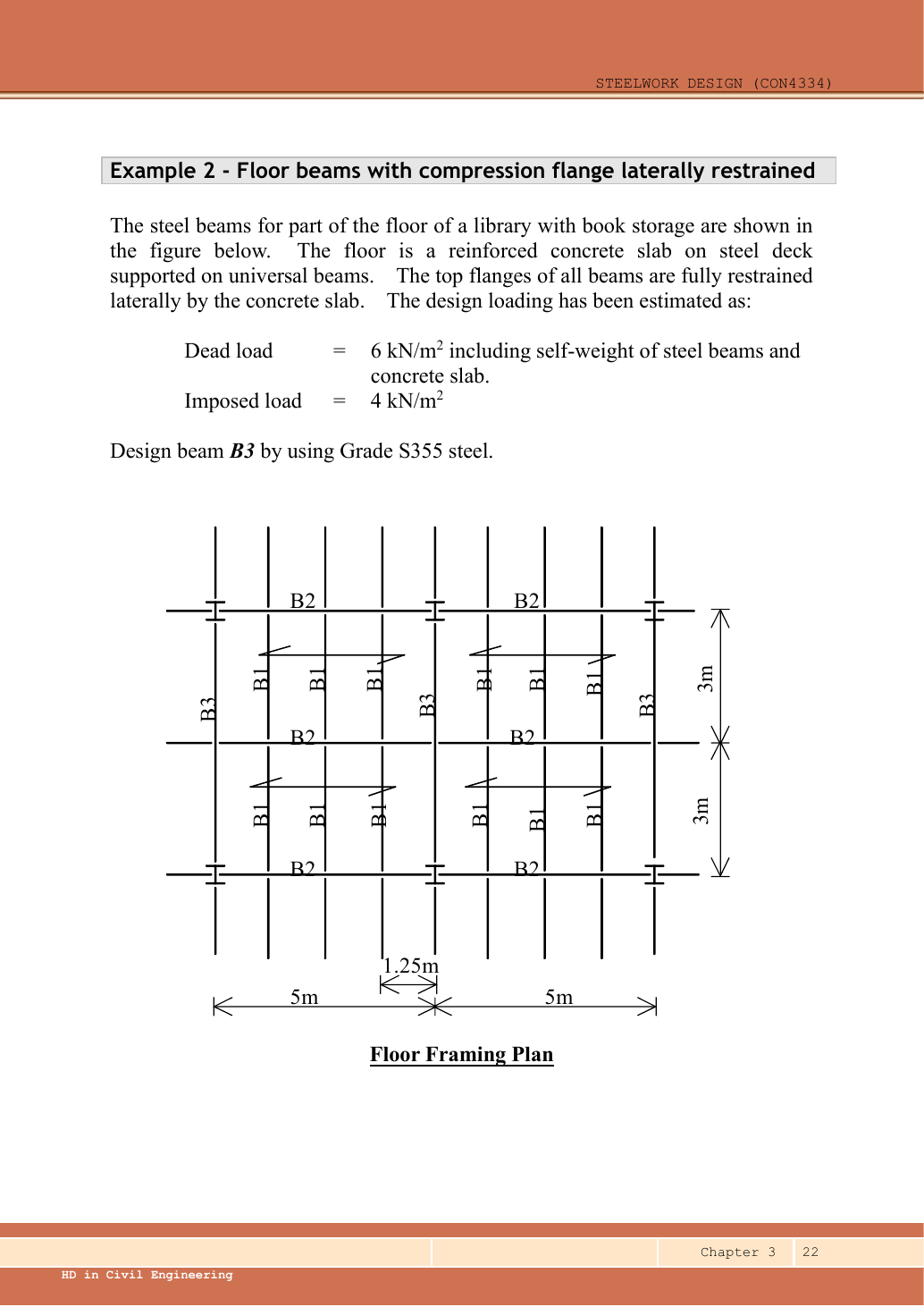
Design the fully restrained supporting beam B3 in the library floor plan. Characteristic dead and imposed floor loads are and ; the dead load includes the self-weight allowances used by the example. Use S355 and the lecturer’s simply supported member model.
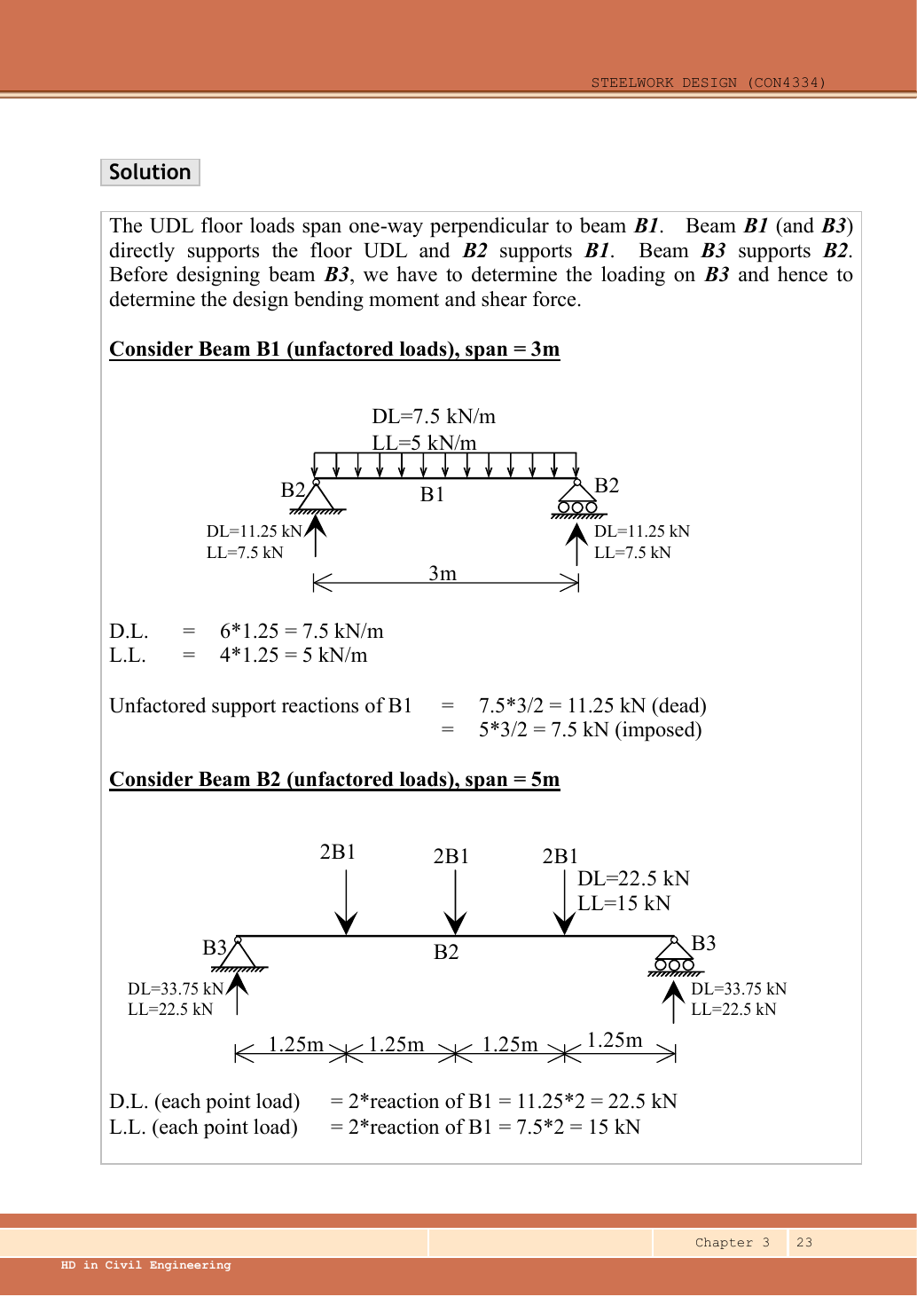
Original source: LectureNotes/Ch 3_Beam.pdf — p. 22, p. 23, p. 24, p. 25, p. 26.
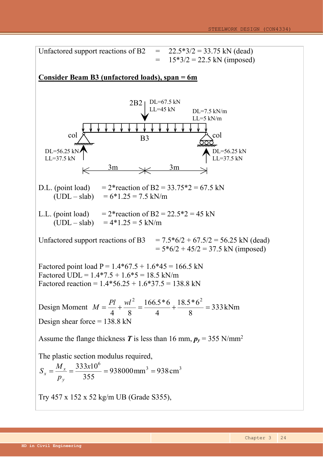
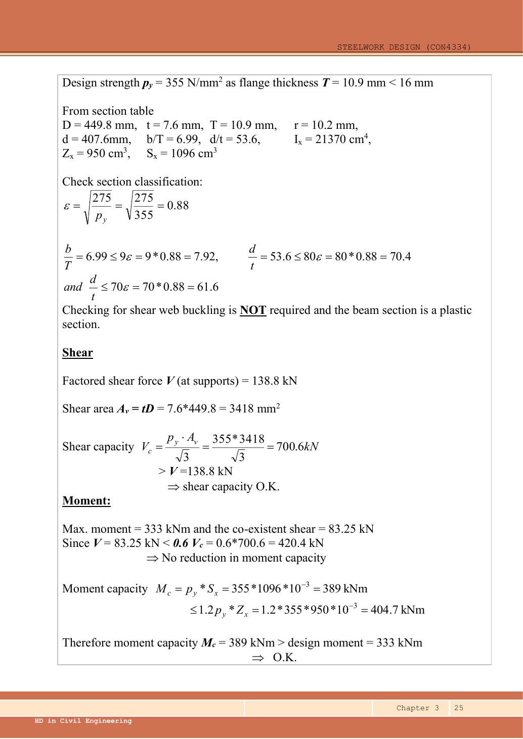
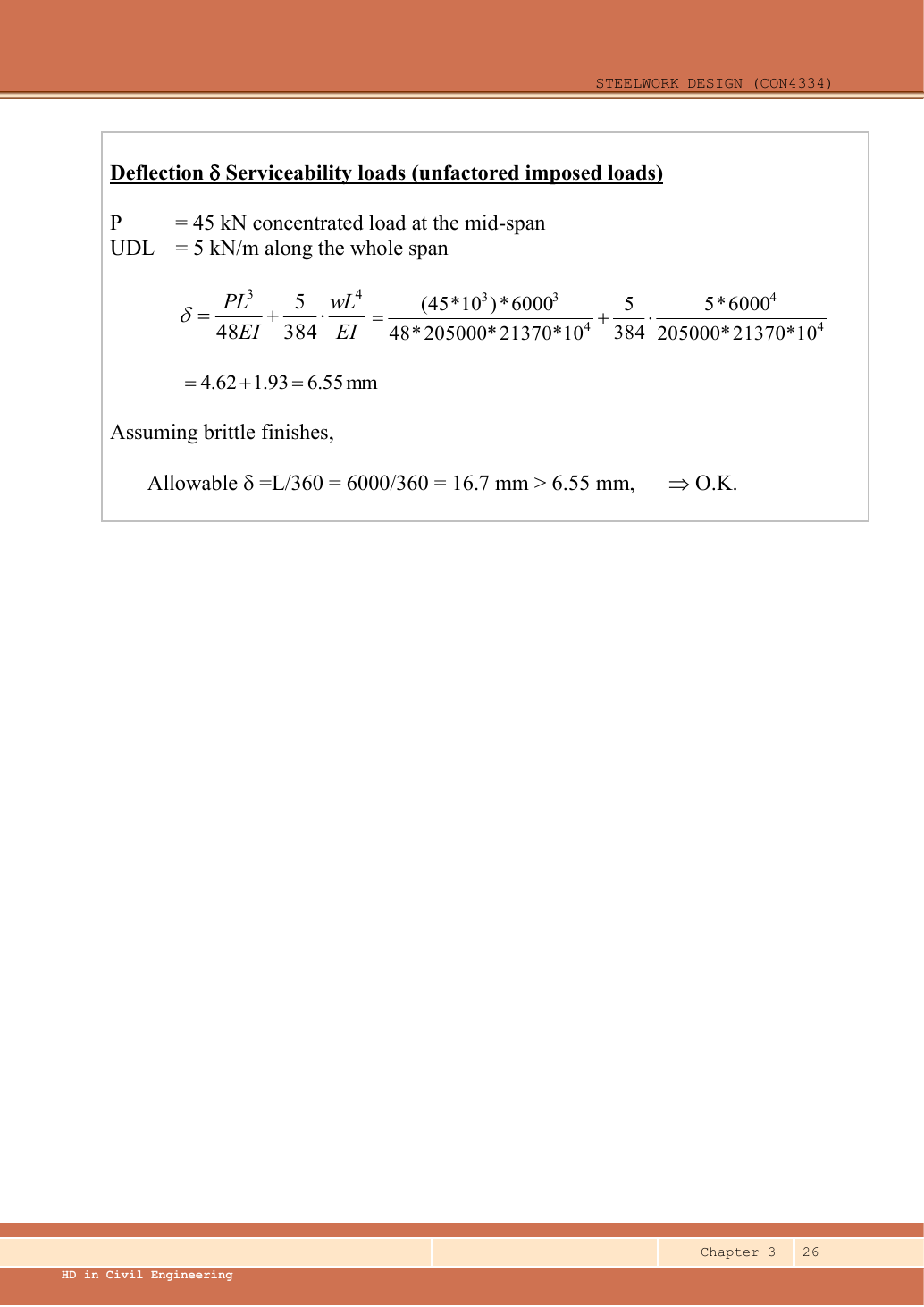
A given value comes from the question or diagram.
A lookup value comes from the named table.
A calculated value follows from the working.
Each assumption is stated where the calculation needs it.
Known information, diagram labels and unknowns
Use the same mechanism: A safe beam can still sag too far. For the same UDL and stiffness, doubling span multiplies deflection by sixteen. Doubling I halves deflection.
Use the same mechanism: Follow one strip of floor. At fixed area load, twice the tributary width gives twice the line load. An end reaction remains a concentrated force.
Apply the reasoning to this section’s data and conditions
| Feature | Meaning for loading |
|---|---|
| Slab span marks crossing the B1 lines | Slab load reaches the parallel B1 beams over a tributary width. |
| B1 above and below each interior B2 | Each B2 loading point receives two B1 end reactions. |
| B2 on both sides of the interior B3 | B3 receives two B2 end reactions at its centre. |
| B3 also directly borders slab strips | Interior B3 carries its own tributary slab strip, represented as a UDL. |
| Given and assumed | All self-weight is already allowed for in the supplied dead intensity. B3 fully restrained; lecturer assumes brittle finishes for serviceability. |
Why this method applies
Use the same mechanism: Balance the isolated beam. Move the same load toward B. Reaction B increases because the load has a larger moment arm about A.
Apply the reasoning to this section’s data and conditions
Work upstream before downstream: slab → B1 → B2 → B3.
A supporting beam receives a point load equal to the end reaction of the supported beam, not that beam’s entire load.
Keep dead and imposed reactions separate until the B3 loading is established.
Do not treat the horizontal bay width as the B3 span.
1. Slab to B1
Use the same mechanism: Follow one strip of floor. At fixed area load, twice the tributary width gives twice the line load. An end reaction remains a concentrated force.
Use the same mechanism: Balance the isolated beam. Move the same load toward B. Reaction B increases because the load has a larger moment arm about A.
Apply the reasoning to this section’s data and conditions
The division by two comes from a uniformly loaded simply supported span.
These are characteristic reactions, before the ultimate factors.
Mechanism detailsFollow the floor load in 3D
The complete mechanism is explained below.
Read each stage together with its stated conditions; playback and interaction are not required.
The floor carries pressure in .
The highlighted strip belongs to one secondary beam.
Multiply pressure by tributary width: .
The illustration uses .
- A primary beam receives the secondary beam reaction at their connection, not a new full-span UDL.
Trace reactions down to columns and foundations.
Count each loaded area once.
2. B1 reactions to B2
Use the same mechanism: Follow one strip of floor. At fixed area load, twice the tributary width gives twice the line load. An end reaction remains a concentrated force.
Use the same mechanism: Balance the isolated beam. Move the same load toward B. Reaction B increases because the load has a larger moment arm about A.
Apply the reasoning to this section’s data and conditions
There are three internal point loads, not four: four slab strips are bounded by three interior B1 lines and the two B3 boundaries.
Symmetry of the three loads gives half the total at each B2 end.
Loads arriving directly at column-supported beam ends do not add span bending.
Mechanism detailsFollow the floor load in 3D
The complete mechanism is explained below.
Read each stage together with its stated conditions; playback and interaction are not required.
The floor carries pressure in .
The highlighted strip belongs to one secondary beam.
Multiply pressure by tributary width: .
The illustration uses .
- A primary beam receives the secondary beam reaction at their connection, not a new full-span UDL.
Trace reactions down to columns and foundations.
Count each loaded area once.
3. Assemble B3 point load and direct slab UDL
Use the same mechanism: Follow one strip of floor. At fixed area load, twice the tributary width gives twice the line load. An end reaction remains a concentrated force.
Use the same mechanism: Keep load categories separate. Increasing imposed load changes its own term. It does not change the dead-load factor or the steel stiffness.
Apply the reasoning to this section’s data and conditions
Physical interpretation: How a floor load reaches a beam
Each beam collects the load from its own strip of floor.
Sketch, not to scale; use the original dimensions.
- Find the tributary width from the actual plan.
- Area load × tributary width gives load per beam length.
- A supporting beam receives the other beam’s end reaction.
Remember: A reaction becomes a point load, not automatically a UDL.
The factor of two at the central point represents the B2 on each side of B3.
It does not double B3’s span or its tributary strip.
Mechanism detailsFollow the floor load in 3D
The complete mechanism is explained below.
Read each stage together with its stated conditions; playback and interaction are not required.
The floor carries pressure in .
The highlighted strip belongs to one secondary beam.
Multiply pressure by tributary width: .
The illustration uses .
- A primary beam receives the secondary beam reaction at their connection, not a new full-span UDL.
Trace reactions down to columns and foundations.
Count each loaded area once.
4. Reactions, shear and moment of B3
Use the same mechanism: Balance the isolated beam. Move the same load toward B. Reaction B increases because the load has a larger moment arm about A.
Use the same mechanism: A cut reveals the internal actions. Under a uniform downward load, shear falls steadily. Moment reaches a stationary value where shear becomes zero.
Apply the reasoning to this section’s data and conditions
Physical interpretation: Why reactions balance the loads
Think of a seesaw that must neither fall nor turn.
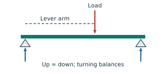
Sketch, not to scale; use the original dimensions.
- Upward and downward forces must balance.
- Take moments about a support to eliminate its reaction.
- Use perpendicular distance from the point to the force line.
Remember: A lateral restraint is not automatically a vertical support.
Mechanism detailsBalance reactions and moments
The complete mechanism is explained below.
Read each stage together with its stated conditions; playback and interaction are not required.
This demonstrator is a simply supported 6 m beam with a 60 kN point load.
It is not the page’s original loading diagram.
.
Moving the load towards B increases .
.
The two upward reactions must sum to P.
With the load at midspan, .
End couples, UDLs and overhangs require their own equilibrium terms.
5. Select UB
Use the same mechanism: A table value has conditions. A different flange thickness can select a lower design strength even when the steel grade name remains unchanged.
Use the property for the physical question
A section table contains several numbers. Choose the property that matches the calculation and bending axis.
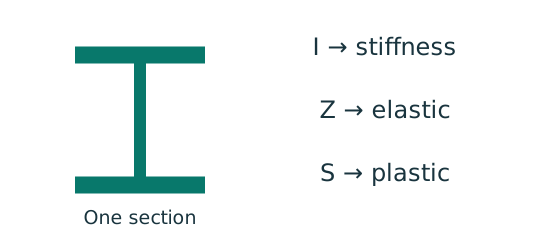
Prediction, then explanation. Moving equal area away from an axis increases I about that axis. It does not increase total area.
Each small area contributes its area multiplied by squared distance. Sum those contributions to obtain I.
I is second moment of area in mm⁴. y is distance from the chosen axis in mm. A is area in mm². r is radius of gyration in mm.
Scope. Z is elastic section modulus; S is plastic section modulus in this course. Neither is interchangeable with I.
Check and takeaway. A nominal section designation is a row identifier. Use the actual dimensions and units in that exact row.
Use the same mechanism: Internal tension and compression resist moment. A larger appropriate section modulus raises resistance at fixed strength. Local plate buckling can restrict the usable modulus.
Apply the reasoning to this section’s data and conditions
Data File p.9 row gives , , , , , and .
Page 10, the same designation, gives , , .
confirms pᵧ=355.
No interpolation is used for section properties: read the exact row.
Mechanism detailsRead a table without losing the keys
The complete mechanism is explained below.
Read each stage together with its stated conditions; playback and interaction are not required.
- Name the required property: material strength, section property, buckling strength or a moment factor.
- Keep section size, steel grade, thickness band, curve and axis as separate lookup keys.
, and require different conversion powers.
Do not use adjacent columns interchangeably.
Use bracketing rows within the same valid column.
The original page remains the source of all table values.
6. Classify the trial section
Use the same mechanism: Find which plate buckles first. At fixed width, a thinner plate has a larger width-to-thickness ratio. Local buckling then becomes more restrictive.
Use the same mechanism: A table value has conditions. A different flange thickness can select a lower design strength even when the steel grade name remains unchanged.
Apply the reasoning to this section’s data and conditions
Mechanism detailsWhy thin elements buckle locally
The complete mechanism is explained below.
Read each stage together with its stated conditions; playback and interaction are not required.
- The flange outstand and web have different widths, thicknesses and edge support conditions.
- A thinner plate can wrinkle locally before the complete member loses stability.
Class 1 allows plastic rotation.
Class 2 reaches plastic resistance.
Class 3 reaches elastic resistance.
Class 4 requires effective properties.
Check every relevant compression element with the supplied limits and stress distribution.
The deformation shown is qualitative.
7. Check shear resistance
Use the same mechanism: The web carries the shear check. At fixed design strength and depth, increasing web thickness increases this shear resistance.
Apply the reasoning to this section’s data and conditions
Mechanism detailsSee shear in the web
The complete mechanism is explained below.
Read each stage together with its stated conditions; playback and interaction are not required.
- Internal shear keeps the two sides of the cut in vertical equilibrium.
For the course’s common I-section case, the web provides the principal shear area.
Use the specified definition.
- A slender web may require a different shear-buckling route before a simple shear-resistance formula is used.
Use where applicable in the course.
Convert N to kN before comparing with design shear.
8. Check moment resistance
Use the same mechanism: Internal tension and compression resist moment. A larger appropriate section modulus raises resistance at fixed strength. Local plate buckling can restrict the usable modulus.
Apply the reasoning to this section’s data and conditions
Physical interpretation: Why one flange squeezes and the other stretches
Bending makes opposite sides of the section do opposite jobs.
Sketch, not to scale; use the original dimensions.
- Find the moment from the actual loads and supports.
- Choose the resistance formula allowed by the section class.
- Check whether the coexistent shear changes that formula.
Remember: Use shear at the location being checked, not an unrelated maximum.
The source’s requested B3 design demonstrates shear, moment and deflection.
It does not specify a bearing geometry for a numerical local-web design here.
Do not import the bearing from Example 1.
Mechanism detailsCompression and tension across a section
The complete mechanism is explained below.
Read each stage together with its stated conditions; playback and interaction are not required.
- For sagging, the top flange is in compression and the bottom in tension; hogging reverses this.
- Elastic bending stress varies with distance from the neutral axis: .
- The section class governs whether elastic, plastic or effective properties may be used.
Use the shear at the section under examination.
The largest shear elsewhere is not automatically coexistent.
9. Check B3 serviceability
Use the same mechanism: A safe beam can still sag too far. For the same UDL and stiffness, doubling span multiplies deflection by sixteen. Doubling I halves deflection.
Apply the reasoning to this section’s data and conditions
Physical interpretation: How much does the beam sag?
Strength asks whether it fails; deflection asks how far it moves.
Sketch, not to scale; use the original dimensions.
- Use the serviceability load case specified by the course question.
- Choose the expression matching the support and load positions.
- Use consistent units for load, length, E and I.
Remember: The largest deflection is not always at midspan.
Mechanism detailsSee stiffness and deflection
The complete mechanism is explained below.
Read each stage together with its stated conditions; playback and interaction are not required.
Use the specified SLS load, span and support arrangement.
The demonstrator has a full-span UDL.
The loaded beam bends.
The deformation is exaggerated so its shape can be seen.
For a simply supported full-span UDL, .
Double L with w, E and I unchanged: δ becomes 16 times as large.
The readout uses , and .
Select the finish/support-specific limit from the original table.
Result and concise exam wording
Use the same mechanism: Balance the isolated beam. Move the same load toward B. Reaction B increases because the load has a larger moment arm about A.
Apply the reasoning to this section’s data and conditions
B1 characteristic reactions /=/.
B2 has three / points; end reactions /.
B3 central /=/ plus /.
Ultimate , , , .
Select UB S355, Class 1: , , .
The demonstrated checks pass.
Misconceptions and checks
Use the same mechanism: Follow one strip of floor. At fixed area load, twice the tributary width gives twice the line load. An end reaction remains a concentrated force.
Apply the reasoning to this section’s data and conditions
- Do not make floor pressure a beam UDL without multiplying by tributary width.
- Do not transfer a supported beam’s entire load to each end.
- Include B3’s directly supported slab strip once.
- Do not add self-weight already included by the problem.
How the method transfers to a new variant
Use the same mechanism: Find which plate buckles first. At fixed width, a thinner plate has a larger width-to-thickness ratio. Local buckling then becomes more restrictive.
Use the same mechanism: A safe beam can still sag too far. For the same UDL and stiffness, doubling span multiplies deflection by sixteen. Doubling I halves deflection.
Use the same mechanism: Vertical bending can trigger sideways motion. Adding a valid lateral restraint shortens a stability segment. It need not change the beam’s vertical reaction or moment diagram.
Apply the reasoning to this section’s data and conditions
- Identify the vertical supports, span, lateral restraints and individual load positions.
- Keep dead and imposed loads separate; form the required ultimate and serviceability cases.
- Find reactions and the maximum shear/moment by equilibrium, with units.
- Choose a section-table row, confirm thickness-dependent strength, and classify both flange and web.
Check shear and bending.
Add segment LTB where restraint is discrete.
- Complete the requested web and deflection checks; state the governing result and any missing data.
Prediction with explained answer
Use the same mechanism: A safe beam can still sag too far. For the same UDL and stiffness, doubling span multiplies deflection by sixteen. Doubling I halves deflection.
Apply the reasoning to this section’s data and conditions
Prediction and explained answer.
Invented variant: only the characteristic floor imposed pressure rises from to .
Find the revised B3 ultimate and , and imposed deflection; retain the original dead loading.
Answer and reasoning
All imposed effects multiply by .
B3 imposed point; imposed UDL.
;
Imposed deflection=
Maximum shear=; these checks still pass.
Mechanism detailsFollow the floor load in 3D
The complete mechanism is explained below.
Read each stage together with its stated conditions; playback and interaction are not required.
The floor carries pressure in .
The highlighted strip belongs to one secondary beam.
Multiply pressure by tributary width: .
The illustration uses .
- A primary beam receives the secondary beam reaction at their connection, not a new full-span UDL.
Trace reactions down to columns and foundations.
Count each loaded area once.
Mechanism detailsFollow the calculation sequence
The complete mechanism is explained below.
Read each stage together with its stated conditions; playback and interaction are not required.
- Locate the load, supports, connection geometry and any stated assumptions.
- Keep given values, table lookups and calculated values distinct; reconcile their units.
- The calculation player steps through the existing expressions in their original order.
Compare demand with resistance or the relevant limit.
Keep missing inputs and conditional conclusions explicit.
8. Normal versus destabilizing loads
Use the same mechanism: Vertical bending can trigger sideways motion. Adding a valid lateral restraint shortens a stability segment. It need not change the beam’s vertical reaction or moment diagram.
Apply the reasoning to this section’s data and conditions
In the source destabilizing case, dominant loads act on the top flange.
Both the load and flange can deflect and rotate relative to the shear centre.
That movement increases the overturning effect as the beam twists.
A downward arrow above the beam does not establish those movement conditions.
Use the stated “normal load” assumption when given.
Otherwise inspect load application and restraints.
Mechanism detailsA beam bends sideways and twists
The complete mechanism is explained below.
Read each stage together with its stated conditions; playback and interaction are not required.
- For the illustrated sagging beam the top flange is compressed.
- The unrestrained compression flange can move sideways while the complete cross-section twists.
Only effective restraints divide the member into unbraced segments.
They do not automatically add vertical supports.
Use the segment effective length, section properties and matching moment factor.
This is an exaggerated mode shape, not a calculated displacement.
9. Select the LTB effective length from restraints
Use the same mechanism: Vertical bending can trigger sideways motion. Adding a valid lateral restraint shortens a stability segment. It need not change the beam’s vertical reaction or moment diagram.
Apply the reasoning to this section’s data and conditions
Physical interpretation: Which length belongs in the calculation?
A sideways tie can shorten the buckling region without shortening the beam’s vertical span.
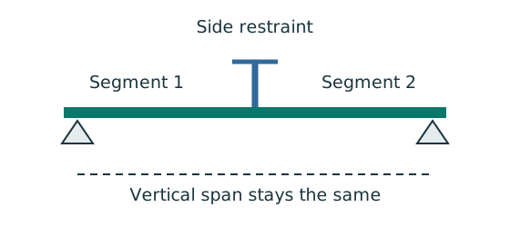
Sketch, not to scale; use the original dimensions.
- Separate vertical-support spacing from lateral-restraint spacing.
- Apply the course rule for the actual end restraint and loading.
- Keep the original vertical load analysis unless its supports change.
Remember: Restraints in one direction may not restrain the other direction.
| Source condition, Ch 3 p.9 | Effective length for normal load |
|---|---|
| End compression-flange lateral restraint, free rotation in plan, nominal torsional restraint | |
| Compression flange fully restrained against rotation in plan at end supports | |
End compression flanges not laterally restrained. Both flanges free to rotate in plan | |
| Adequate intermediate lateral restraints | Lᴇ=segment length Lᴸᵀ |
For the destabilizing cases described on p.9 multiply the relevant length by ; intermediate segments use 1.2Lᴸᵀ.
A question may explicitly direct that effective and actual segment lengths are equal; follow that instruction.
Cantilevers need Table 8.1: match the support condition, tip restraint and normal/destabilizing column, rather than borrowing the simply supported rule.
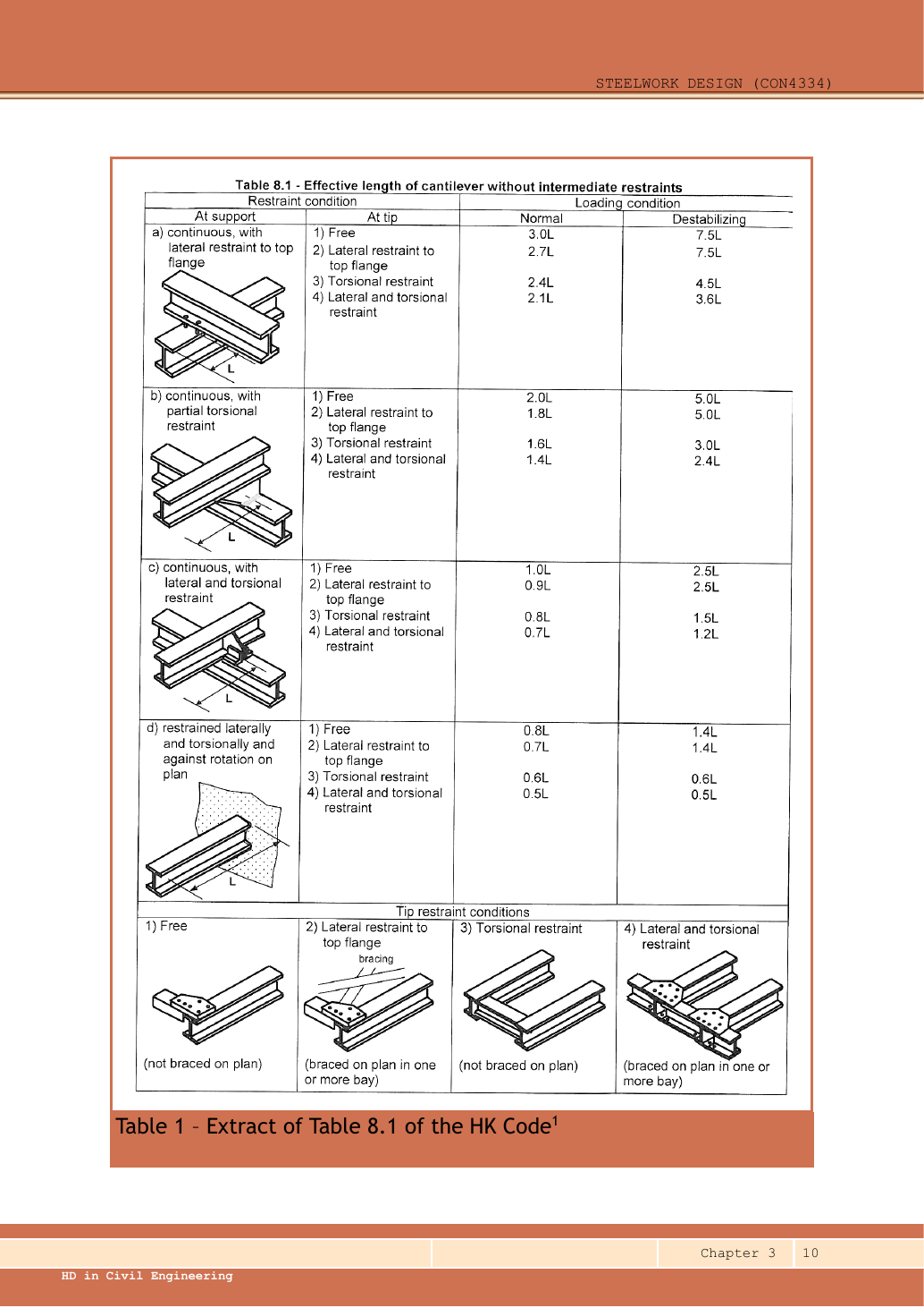
Original Table 8.1, Ch 3 p.10.
Four tip conditions are sketched at the bottom.
Support groups: (a) continuous member with lateral restraint to the top flange; (b) continuous member with partial torsional restraint; (c) continuous member with lateral and torsional restraint; (d) restrained against lateral displacement, twist and rotation in the plane of bending.
Within every group, tip conditions 1–4 are: 1 free; 2 top flange laterally restrained; 3 torsionally restrained; 4 laterally and torsionally restrained.
Tip sketches 1 and 3 have no plan bracing; sketches 2 and 4 show plan bracing in one or more bays.
The following values transcribe the source row by row, each pair in the order normal loading / destabilizing loading:(a1) /; (a2) /; (a3) /; (a4) /. (b1) /; (b2) /; (b3) /; (b4) /. (c1) /; (c2) /; (c3) /; (c4) /. (d1) /; (d2) /; (d3) /; (d4) /.
First choose the support block, a–d.
Next choose the tip row, 1–4.
Finally choose the load-condition column.
Example of reading, not an extra code rule: block (c), free tip row 1, normal loading gives .
The same geometry under destabilizing loading gives .
The explicit overhang effective-length assumption in Tutorial 3 Q5 takes precedence for that exercise.
Mechanism detailsA beam bends sideways and twists
The complete mechanism is explained below.
Read each stage together with its stated conditions; playback and interaction are not required.
- For the illustrated sagging beam the top flange is compressed.
- The unrestrained compression flange can move sideways while the complete cross-section twists.
Only effective restraints divide the member into unbraced segments.
They do not automatically add vertical supports.
Use the segment effective length, section properties and matching moment factor.
This is an exaggerated mode shape, not a calculated displacement.
10. Convert unbraced length to a resistance
Use the same mechanism: Vertical bending can trigger sideways motion. Adding a valid lateral restraint shortens a stability segment. It need not change the beam’s vertical reaction or moment diagram.
Use the same mechanism: A table value has conditions. A different flange thickness can select a lower design strength even when the steel grade name remains unchanged.
Apply the reasoning to this section’s data and conditions
Physical interpretation: A beam can escape sideways
The compressed flange can move sideways while the section twists.
Sketch, not to scale; use the original dimensions.
- Divide the beam at effective lateral restraints.
- Use each segment’s effective length to obtain its buckling resistance.
- Compare that resistance with the segment’s equivalent moment demand.
Remember: A section bending check alone does not check lateral-torsional buckling.
is weak-axis radius of gyration, in the same units as .
is the section buckling parameter and the torsional index, both read from the selected section’s property row.
This is not the beam position coordinate used in equilibrium.
for Classes 1 and 2.
Do not assume that value for an unestablished Class 3/4 treatment.
The source allows conservative and for rolled-section preliminary checks; accurate values matter in tight examples.
Select the design strength column within the steel grade: S355 with uses , not the column.
Find the two rows surrounding the calculated value and interpolate linearly.
Never use directly as the table row.
A larger slenderness normally lowers .
Prediction and explained answer. λᴸᵀ=121.6 and pᵧ=355.
Rows and give and .
Find pᵦ.
Answer and reasoning
Interpolation fraction .
, conventionally written .
Mechanism detailsA beam bends sideways and twists
The complete mechanism is explained below.
Read each stage together with its stated conditions; playback and interaction are not required.
- For the illustrated sagging beam the top flange is compressed.
- The unrestrained compression flange can move sideways while the complete cross-section twists.
Only effective restraints divide the member into unbraced segments.
They do not automatically add vertical supports.
Use the segment effective length, section properties and matching moment factor.
This is an exaggerated mode shape, not a calculated displacement.
Mechanism detailsA beam bends sideways and twists
The complete mechanism is explained below.
Read each stage together with its stated conditions; playback and interaction are not required.
- For the illustrated sagging beam the top flange is compressed.
- The unrestrained compression flange can move sideways while the complete cross-section twists.
Only effective restraints divide the member into unbraced segments.
They do not automatically add vertical supports.
Use the segment effective length, section properties and matching moment factor.
This is an exaggerated mode shape, not a calculated displacement.
11. Use the moment shape of each unbraced segment
Moment shape matters within one segment
Represent a nonuniform moment distribution in the applicable member-buckling equation.
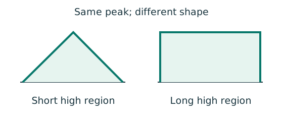
Prediction, then explanation. Two segments can have equal peak moment but different distributions. Their equivalent moment factors can therefore differ.
Evaluate moments from the true whole-beam analysis at the required positions. Apply the exact table’s weights, signs and lower bound.
mLT is an LTB factor. mx and my belong to the specified flexural checks. They are not interchangeable.
Scope. Some rules use magnitudes; others require signed ordinates. A factor does not reduce the actual moment used in a local section check.
Check and takeaway. Measure quarter points from the segment start, not automatically from the beam’s left support.
Apply the reasoning to this section’s data and conditions
Physical interpretation: Why the shape of the moment diagram matters
The same peak moment is more demanding when a long region stays near that peak.
Sketch, not to scale; use the original dimensions.
- Use the diagram of this unrestrained segment.
- Choose the applicable course sketch or quarter-point rule.
- Apply its factor to the demand, following the stated check.
Remember: Column flexural-buckling factors and LTB factors are not interchangeable.
A short region at the maximum moment is less severe for LTB than the whole segment at that moment.
The equivalent uniform moment factor accounts for this.
Choose Table 8.4a only when the actual load/moment pattern matches its sketch.
For a straight end-moment diagram, use the signed ratio of the smaller to the larger internal end moment: .
Check the source sketch’s sign convention: applied end arrows and internal BMD signs are not interchangeable.
The table instructs that the ordinates are taken positive.
Use their magnitudes even if the BMD reverses sign.
Quarter points refer to the current segment, not the full beam.
Calculate their moments from equilibrium, retaining UDL curvature.
For a cantilever without intermediate restraints the source sets .
If a segment has zero moment throughout, there is no bending demand.
Do not divide by zero.
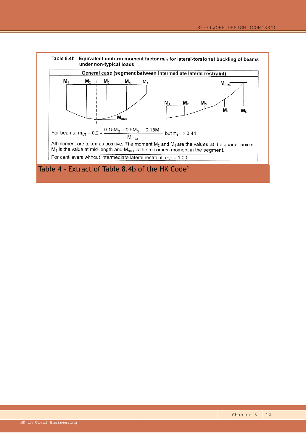
Table 8.4b, Ch 3 p.16: quarter-point positions and moment diagrams with single curvature or a change of sign.
The source formula is:It must also satisfy .
The source specifies that all moments are taken as positive.
, are the two quarter-point values.
is the midpoint value.
is the maximum within the segment.
The labels , are at the segment ends.
The left-hand diagram retains one sign.
The right-hand diagram crosses zero and changes sign.
A cantilever without an intermediate lateral restraint uses .
Mechanism detailsRead the moment shape within one segment
The complete mechanism is explained below.
Read each stage together with its stated conditions; playback and interaction are not required.
- Moment ordinates must belong to the same effective unbraced segment.
- Same-side and reverse-curvature diagrams have different signed end ratios.
- The markers show ¼, ½ and ¾ of this segment, not of the entire beam.
LTB and column flexural factors are different.
Preserve their individual bounds and coefficient sets.
12. Put the checks together
Use the same mechanism: Vertical bending can trigger sideways motion. Adding a valid lateral restraint shortens a stability segment. It need not change the beam’s vertical reaction or moment diagram.
Use the same mechanism: Moment shape matters within one segment. Two segments can have equal peak moment but different distributions. Their equivalent moment factors can therefore differ.
Use the same mechanism: A cut reveals the internal actions. Under a uniform downward load, shear falls steadily. Moment reaches a stationary value where shear becomes zero.
Apply the reasoning to this section’s data and conditions
- Finish whole-beam reactions and SFD/BMD using the actual vertical supports.
- Mark every lateral restraint and divide into unbraced segments.
- For each segment establish Lᴇ, , , λᴸᵀ and pᵦ; compute Mᵦ.
Find the segment’s maximum moment and its matching mᴸᵀ.
Check mᴸᵀMmax≤Mᵦ.
- Separately check actual and , plus high-shear interaction if necessary.
Complete required bearing, web buckling and deflection checks.
Report the governing segment and any missing inputs.
Do not assume the segment with the highest moment always governs: a longer, more weakly restrained segment may have a much smaller resistance.
Keep a table of demand, resistance and utilisation for all segments.
Beam example 3: three restrained segments and an omitted deflection solution
Open this example on its own page
Check/design the S355 simply supported beam for shear and bending with lateral restraints at A, B, C and D. . At B: dead and imposed ; at C: dead and imposed . Dead self-weight is . Effective segment lengths equal actual lengths. Also work through the lecturer’s requested follow-up web and deflection checks.
Original source: LectureNotes/Ch 3_Beam.pdf — p. 27, p. 28, p. 29, p. 30.
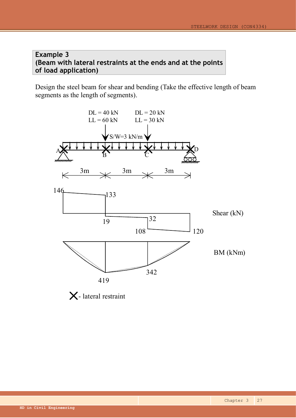
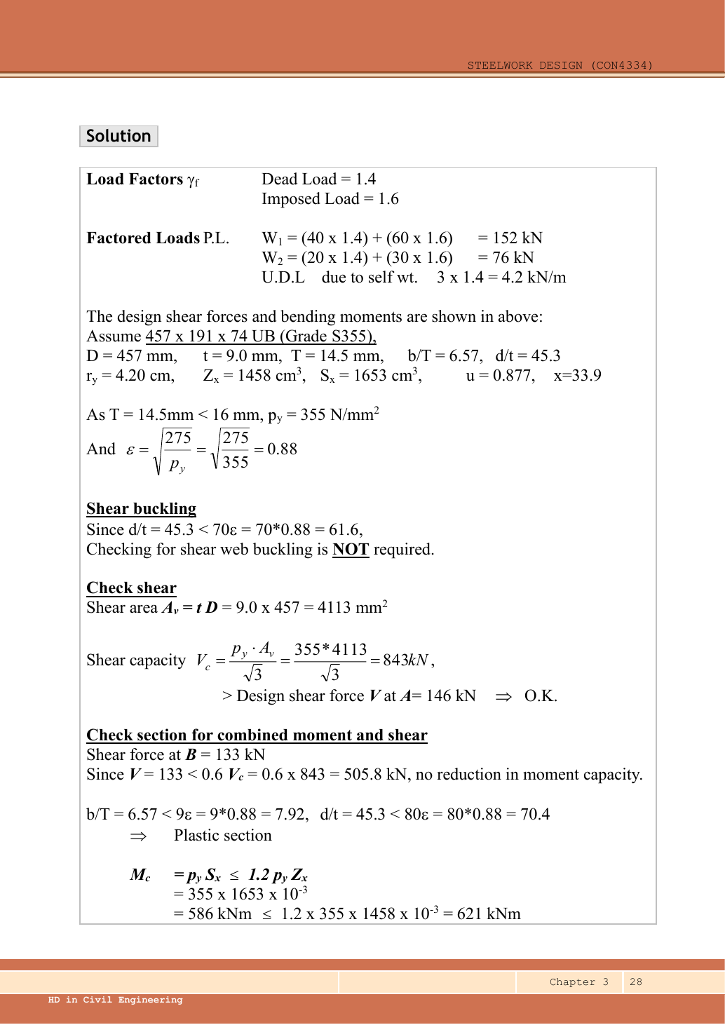
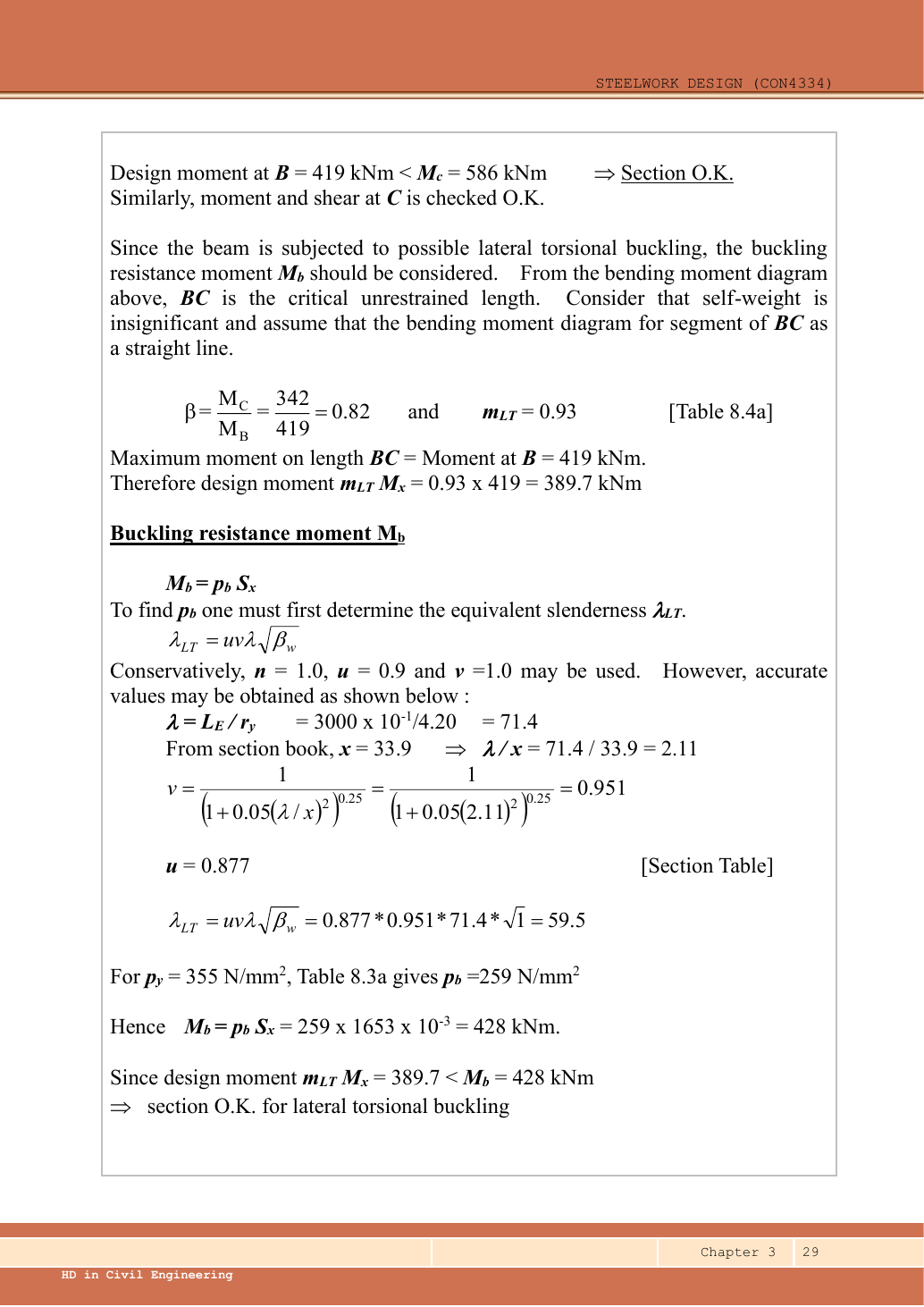
A given value comes from the question or diagram.
A lookup value comes from the named table.
A calculated value follows from the working.
Each assumption is stated where the calculation needs it.
Known information, diagram labels and unknowns
Use the same mechanism: The loaded web can act as a short strut. Reduced local restraint can increase the relevant effective length and reduce local buckling resistance.
Use the same mechanism: A concentrated force spreads into the web. A longer valid stiff-bearing length can spread the same force over more web. A flexible contact is not automatically stiff bearing.
Use the same mechanism: Vertical bending can trigger sideways motion. Adding a valid lateral restraint shortens a stability segment. It need not change the beam’s vertical reaction or moment diagram.
Apply the reasoning to this section’s data and conditions
| Input | Exact diagram or table source |
|---|---|
| Vertical span | Three dimension strings of give . |
| Lateral model | Crosses define three unbraced segments; question sets Lᴇ=3,000 mm. |
| Trial section | The source selects UB. Data pp.9–10 give , , , , ; , ; ; ; , ; , . |
| Missing local-web data | No stiff bearing lengths, distances to member ends or complete local flange-restraint details are given. Crosses alone identify lateral restraint, not both web-buckling conditions. |
Why this method applies
Use the same mechanism: A safe beam can still sag too far. For the same UDL and stiffness, doubling span multiplies deflection by sixteen. Doubling I halves deflection.
Use the same mechanism: A cut reveals the internal actions. Under a uniform downward load, shear falls steadily. Moment reaches a stationary value where shear becomes zero.
Use the same mechanism: A table value has conditions. A different flange thickness can select a lower design strength even when the steel grade name remains unchanged.
Apply the reasoning to this section’s data and conditions
Analyse the continuous beam on its two vertical supports.
Use that BMD to examine the three separate lateral-buckling segments.
First reproduce the lecturer’s rounded, straight-line BC approximation, then retain the self-weight curvature with Table 8.4b to check every segment.
Deflection uses the imposed loads and at their actual off-centre positions.
A central-point formula cannot be substituted.
1. Factored loads
Use the same mechanism: Keep load categories separate. Increasing imposed load changes its own term. It does not change the dead-load factor or the steel stiffness.
Apply the reasoning to this section’s data and conditions
Mechanism detailsFrom characteristic to design load
The complete mechanism is explained below.
Read each stage together with its stated conditions; playback and interaction are not required.
G is permanent load; Q is imposed load.
A surface load and a line load also have different units.
This illustration uses the course gravity case .
Other combinations in the original text retain their own factors.
- For illustrative , the separate load contributions show what changes when Q increases.
Do not carry this ULS total automatically into deflection.
Follow the stated SLS load case.
2. Reactions without premature rounding
Use the same mechanism: Balance the isolated beam. Move the same load toward B. Reaction B increases because the load has a larger moment arm about A.
Apply the reasoning to this section’s data and conditions
Physical interpretation: Why reactions balance the loads
Think of a seesaw that must neither fall nor turn.
Sketch, not to scale; use the original dimensions.
- Upward and downward forces must balance.
- Take moments about a support to eliminate its reaction.
- Use perpendicular distance from the point to the force line.
Remember: A lateral restraint is not automatically a vertical support.
Take moments about D: each downward load contributes its distance to D.
The UDL resultant acts at midspan, from D.
Check by moments about A:.
Mechanism detailsBalance reactions and moments
The complete mechanism is explained below.
Read each stage together with its stated conditions; playback and interaction are not required.
This demonstrator is a simply supported 6 m beam with a 60 kN point load.
It is not the page’s original loading diagram.
.
Moving the load towards B increases .
.
The two upward reactions must sum to P.
With the load at midspan, .
End couples, UDLs and overhangs require their own equilibrium terms.
3. Construct the SFD and BMD from the left-hand free body
Use the same mechanism: A cut reveals the internal actions. Under a uniform downward load, shear falls steadily. Moment reaches a stationary value where shear becomes zero.
Apply the reasoning to this section’s data and conditions
For moment (), start with ; when , add ; when , also add . Each negative term is a point load times its lever arm to the section; include it only after the section has passed that load.
Read each “when” term as zero before its load position and include it afterwards.
is in metres from A.
The shorthand is often written with positive-part brackets .
It is a beam-position coordinate, unrelated to the torsional index.
| Position | Shear just left / right () | Moment () |
|---|---|---|
| / | ||
| B, | / | |
| C, | / | |
| / |
B is the maximum because shear changes from positive to negative there.
BC and CD have negative shear throughout, so their bending moment decreases.
Draw straight sloping shear segments, vertical jumps at the point loads, and curved bending segments continuous at B and C.
Mechanism detailsBuild the shear and moment diagrams
The complete mechanism is explained below.
Read each stage together with its stated conditions; playback and interaction are not required.
- For the illustrative 60 kN point load on a 6 m simply supported beam, balance the reactions before making a cut.
and before the point load.
Moment grows linearly.
Shear jumps down by P.
To its right, and .
For this case, moment is continuous and returns to zero at B.
A concentrated applied couple instead creates a moment jump.
4. Confirm strength and section class
Use the same mechanism: Find which plate buckles first. At fixed width, a thinner plate has a larger width-to-thickness ratio. Local buckling then becomes more restrictive.
Apply the reasoning to this section’s data and conditions
Mechanism detailsWhy thin elements buckle locally
The complete mechanism is explained below.
Read each stage together with its stated conditions; playback and interaction are not required.
- The flange outstand and web have different widths, thicknesses and edge support conditions.
- A thinner plate can wrinkle locally before the complete member loses stability.
Class 1 allows plastic rotation.
Class 2 reaches plastic resistance.
Class 3 reaches elastic resistance.
Class 4 requires effective properties.
Check every relevant compression element with the supplied limits and stress distribution.
The deformation shown is qualitative.
5. Shear resistance
Use the same mechanism: The web carries the shear check. At fixed design strength and depth, increasing web thickness increases this shear resistance.
Apply the reasoning to this section’s data and conditions
Mechanism detailsSee shear in the web
The complete mechanism is explained below.
Read each stage together with its stated conditions; playback and interaction are not required.
- Internal shear keeps the two sides of the cut in vertical equilibrium.
For the course’s common I-section case, the web provides the principal shear area.
Use the specified definition.
- A slender web may require a different shear-buckling route before a simple shear-resistance formula is used.
Use where applicable in the course.
Convert N to kN before comparing with design shear.
6. Actual section moment resistance
Use the same mechanism: Internal tension and compression resist moment. A larger appropriate section modulus raises resistance at fixed strength. Local plate buckling can restrict the usable modulus.
Apply the reasoning to this section’s data and conditions
Mechanism detailsCompression and tension across a section
The complete mechanism is explained below.
Read each stage together with its stated conditions; playback and interaction are not required.
- For sagging, the top flange is in compression and the bottom in tension; hogging reverses this.
- Elastic bending stress varies with distance from the neutral axis: .
- The section class governs whether elastic, plastic or effective properties may be used.
Use the shear at the section under examination.
The largest shear elsewhere is not automatically coexistent.
7. Check every unbraced segment
Use the same mechanism: Vertical bending can trigger sideways motion. Adding a valid lateral restraint shortens a stability segment. It need not change the beam’s vertical reaction or moment diagram.
Apply the reasoning to this section’s data and conditions
Physical interpretation: A beam can escape sideways
The compressed flange can move sideways while the section twists.
Sketch, not to scale; use the original dimensions.
- Divide the beam at effective lateral restraints.
- Use each segment’s effective length to obtain its buckling resistance.
- Compare that resistance with the segment’s equivalent moment demand.
Remember: A section bending check alone does not check lateral-torsional buckling.
All three segments have the same section and effective length, hence the same buckling resistance.
Use the weak-axis radius .
Lecturer route: approximate BC as straight, .
Read mᴸᵀ≈0.93, giving .
Rounded λᴸᵀ≈59.5 gives pᵦ≈259 and Mᵦ≈428 kNm.
It passes.
To include the UDL exactly, use quarter-point magnitudes from above:
| Segment | Quarter positions from A () | 、、() | () | () |
|---|---|---|---|---|
For AB insert its three ordinates into the same expression:
For CD:
Their factors also exceed .
BC governs and all three pass.
Mechanism detailsA beam bends sideways and twists
The complete mechanism is explained below.
Read each stage together with its stated conditions; playback and interaction are not required.
- For the illustrated sagging beam the top flange is compressed.
- The unrestrained compression flange can move sideways while the complete cross-section twists.
Only effective restraints divide the member into unbraced segments.
They do not automatically add vertical supports.
Use the segment effective length, section properties and matching moment factor.
This is an exaggerated mode shape, not a calculated displacement.
8. The omitted local web checks: what can and cannot be concluded
Use the same mechanism: A concentrated force spreads into the web. A longer valid stiff-bearing length can spread the same force over more web. A flexible contact is not automatically stiff bearing.
Use the same mechanism: The loaded web can act as a short strut. Reduced local restraint can increase the relevant effective length and reduce local buckling resistance.
Use the same mechanism: Vertical bending can trigger sideways motion. Adding a valid lateral restraint shortens a stability segment. It need not change the beam’s vertical reaction or moment diagram.
Apply the reasoning to this section’s data and conditions
Physical interpretation: A concentrated force can hurt one small region
A narrow contact presses much harder locally than the same force spread over a wider contact.
Sketch, not to scale; use the original dimensions.
- Find the actual stiff bearing length and end position.
- Check local crushing and local web buckling separately.
- Use the restraint conditions required by each expression.
Remember: Missing contact dimensions cannot be guessed from drawing scale.
Page 30 asks students to check bearing and web buckling.
However, neither the support bearing geometry nor the load-introduction details at B and C are supplied.
A lateral-restraint cross does not specify stiff-bearing length.
It also does not define loaded-flange rotation relative to the web.
Therefore the supplied data do not establish a numerical local-web result.
Keep that part of the conclusion conditional.
Once ,, and both local restraint conditions are known, evaluate using and the correct end/interior branch in the web-buckling procedure.
If local restraint is absent, Lᴱ,web is also needed.
Do not copy Example 1’s , and values into this different diagram.
The source’s overall “adequate” statement is supported for shear, section bending and LTB, but local-web adequacy is not established by the supplied information.
Mechanism detailsSpread a concentrated force into the web
The complete mechanism is explained below.
Read each stage together with its stated conditions; playback and interaction are not required.
- A concentrated reaction first enters through the bearing/contact region.
- The flange and root geometry spread the force before it enters the web.
- A wider effective bearing region can reduce local stress for the same force.
End distance, stiff bearing length and restraint conditions must come from the original question.
The illustrated dimensions explain the mechanism.
They do not replace the original question data.
9. Complete the omitted off-centre deflection calculation
Use the same mechanism: A safe beam can still sag too far. For the same UDL and stiffness, doubling span multiplies deflection by sixteen. Doubling I halves deflection.
Apply the reasoning to this section’s data and conditions
Physical interpretation: How much does the beam sag?
Strength asks whether it fails; deflection asks how far it moves.
Sketch, not to scale; use the original dimensions.
- Use the serviceability load case specified by the course question.
- Choose the expression matching the support and load positions.
- Use consistent units for load, length, E and I.
Remember: The largest deflection is not always at midspan.
Use only the locations and their imposed loads , and of ; there is no imposed UDL.
This calculation uses , , constant , and exact section-table value .
Imposed-load reactions are , .
The general method starts from the curvature relationship.
Taking downward deflection as positive, .
Integrate the bending moment twice.
Define as follows: when , its value is zero; when , its value is .
Use the support conditions to determine the integration constants.
Maximum downward deflection occurs where slope .
It lies between B and C: slope numerator at is; at it is, and the positive bending moment makes slope decrease continuously.
At midspan the deflection is , close but not the exact maximum.
The source does not specify the finish category for this example.
If the brittle-finish criterion used in preceding examples is adopted explicitly, the limit is and passes.
The calculated deflection is determined.
The acceptance statement is conditional on that chosen serviceability limit.
Mechanism detailsSee stiffness and deflection
The complete mechanism is explained below.
Read each stage together with its stated conditions; playback and interaction are not required.
Use the specified SLS load, span and support arrangement.
The demonstrator has a full-span UDL.
The loaded beam bends.
The deformation is exaggerated so its shape can be seen.
For a simply supported full-span UDL, .
Double L with w, E and I unchanged: δ becomes 16 times as large.
The readout uses , and .
Select the finish/support-specific limit from the original table.
Result and concise exam wording
Use the same mechanism: The loaded web can act as a short strut. Reduced local restraint can increase the relevant effective length and reduce local buckling resistance.
Apply the reasoning to this section’s data and conditions
UB S355 is Class 1.
Rₐ/Rᴅ=/; Mᴮ/Mᶜ=/.
; .
All segments Lᴱ=3 m: λᴸᵀ=59.5807,pᵦ=258.426,Mᵦ=427.178 kNm.
Exact equivalent demands AB/BC/CD//; all pass, BC controls.
Imposed at ; passes if applies.
Local bearing/web-buckling numerical checks are unresolved because bearing and local-restraint data are missing.
Misconceptions and checks
Use the same mechanism: Moment shape matters within one segment. Two segments can have equal peak moment but different distributions. Their equivalent moment factors can therefore differ.
Use the same mechanism: A safe beam can still sag too far. For the same UDL and stiffness, doubling span multiplies deflection by sixteen. Doubling I halves deflection.
Apply the reasoning to this section’s data and conditions
- Do not turn B and C into vertical supports.
- Do not use as the span for the whole-beam deflection.
- Do not omit BC end moments when evaluating its quarter points.
- Do not present assumed bearing dimensions as given.
How the method transfers to a new variant
Use the same mechanism: Find which plate buckles first. At fixed width, a thinner plate has a larger width-to-thickness ratio. Local buckling then becomes more restrictive.
Use the same mechanism: A safe beam can still sag too far. For the same UDL and stiffness, doubling span multiplies deflection by sixteen. Doubling I halves deflection.
Use the same mechanism: Vertical bending can trigger sideways motion. Adding a valid lateral restraint shortens a stability segment. It need not change the beam’s vertical reaction or moment diagram.
Apply the reasoning to this section’s data and conditions
- Identify the vertical supports, span, lateral restraints and individual load positions.
- Keep dead and imposed loads separate; form the required ultimate and serviceability cases.
- Find reactions and the maximum shear/moment by equilibrium, with units.
- Choose a section-table row, confirm thickness-dependent strength, and classify both flange and web.
Check shear and bending.
Add segment LTB where restraint is discrete.
- Complete the requested web and deflection checks; state the governing result and any missing data.
Prediction with explained answer
Use the same mechanism: A safe beam can still sag too far. For the same UDL and stiffness, doubling span multiplies deflection by sixteen. Doubling I halves deflection.
Use the same mechanism: Vertical bending can trigger sideways motion. Adding a valid lateral restraint shortens a stability segment. It need not change the beam’s vertical reaction or moment diagram.
Use the same mechanism: A cut reveals the internal actions. Under a uniform downward load, shear falls steadily. Moment reaches a stationary value where shear becomes zero.
Apply the reasoning to this section’s data and conditions
Prediction and explained answer.
Invented variant: with all loads unchanged, the lateral restraint at C is removed.
Which parts of this solution must be recalculated?
Answer and reasoning
Vertical reactions, whole-beam SFD/BMD, section shear/bending and elastic deflection do not change.
LTB segments become and .
If the same effective-length rule applies, use an effective length of 6,000 mm for BD.
Recompute ,,λᴸᵀ,pᵦ and Mᵦ.
Use quarter positions with the true BD maximum at B.
The point load atC remains even though its lateral restraint is removed.
Mechanism detailsSee stiffness and deflection
The complete mechanism is explained below.
Read each stage together with its stated conditions; playback and interaction are not required.
Use the specified SLS load, span and support arrangement.
The demonstrator has a full-span UDL.
The loaded beam bends.
The deformation is exaggerated so its shape can be seen.
For a simply supported full-span UDL, .
Double L with w, E and I unchanged: δ becomes 16 times as large.
The readout uses , and .
Select the finish/support-specific limit from the original table.
Beam example 4: a tight LTB check with three point loads
Open this example on its own page
Select/check a S355 simply supported beam of span carrying three characteristic point loads, each dead plus imposed, and a dead UDL. Loading is normal. Ends are restrained against torsion, with compression flange free to rotate in plan; there is no intermediate lateral restraint.
Original source: LectureNotes/Ch 3_Beam.pdf — p. 31, p. 32, p. 33.
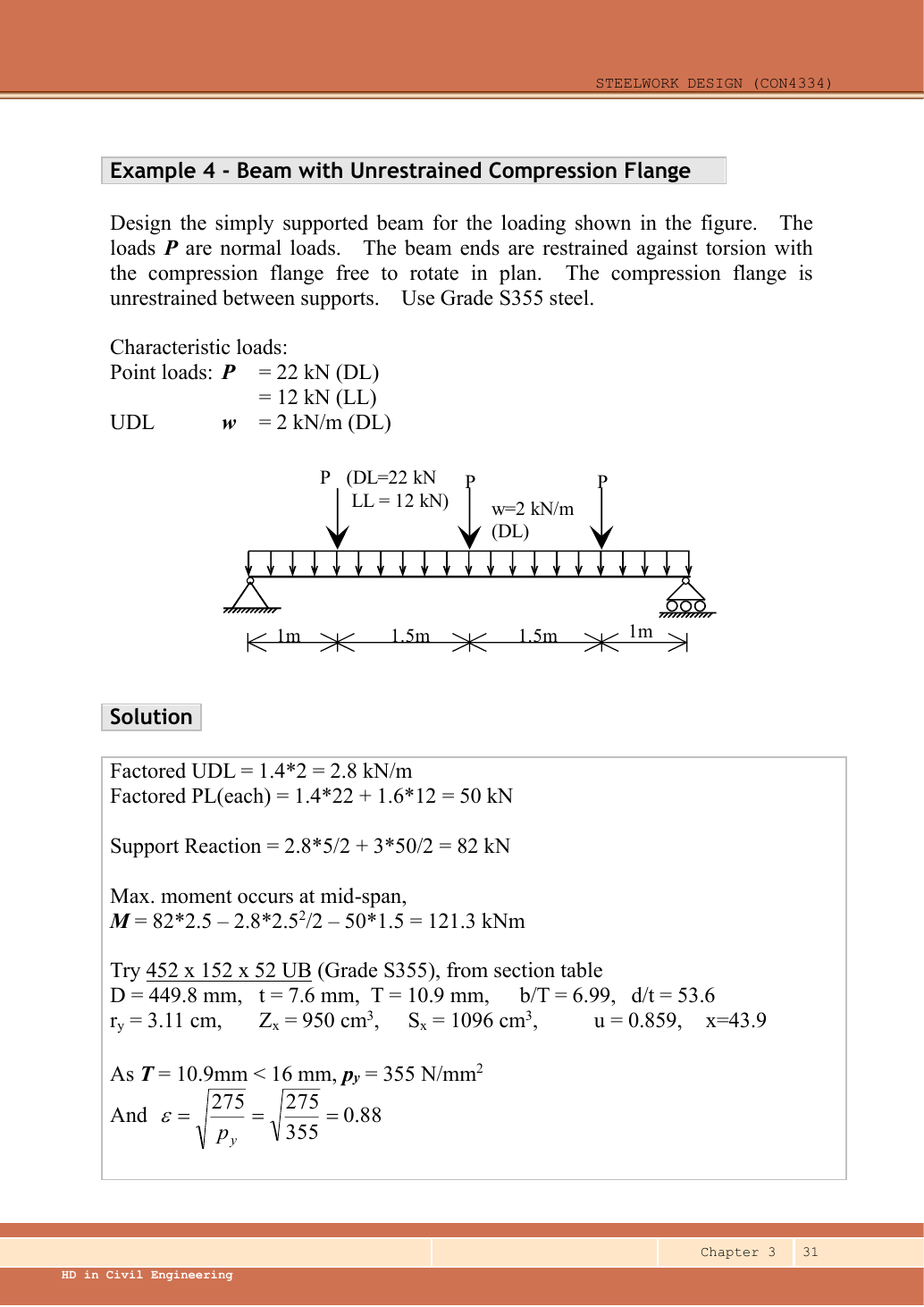
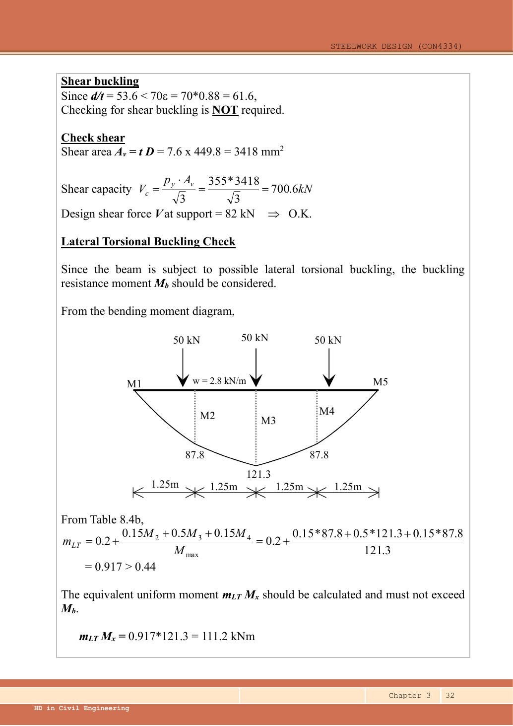
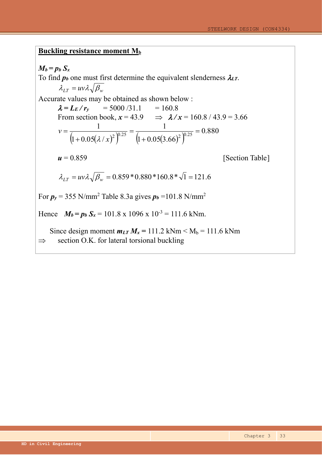
A given value comes from the question or diagram.
A lookup value comes from the named table.
A calculated value follows from the working.
Each assumption is stated where the calculation needs it.
Known information, diagram labels and unknowns
Use the same mechanism: Moment shape matters within one segment. Two segments can have equal peak moment but different distributions. Their equivalent moment factors can therefore differ.
Use the same mechanism: A table value has conditions. A different flange thickness can select a lower design strength even when the steel grade name remains unchanged.
Apply the reasoning to this section’s data and conditions
| Input | Source/use |
|---|---|
| Span and load positions | Given dimension chain; central point is at . |
| Lateral model | The question specifies normal loading, end torsional restraint and free in-plane rotation, so . |
| Trial section | The source properties correspond to UB: , , , , , , , , , . |
| Table source | Data File pp.9–10 exact section row; p.5 Table 8.3a strength; p.6 moment factors. |
Why this method applies
Use the same mechanism: Moment shape matters within one segment. Two segments can have equal peak moment but different distributions. Their equivalent moment factors can therefore differ.
Use the same mechanism: Vertical bending can trigger sideways motion. Adding a valid lateral restraint shortens a stability segment. It need not change the beam’s vertical reaction or moment diagram.
Use the same mechanism: Balance the isolated beam. Move the same load toward B. Reaction B increases because the load has a larger moment arm about A.
Apply the reasoning to this section’s data and conditions
Symmetry makes analysis simple but does not provide lateral restraint.
Check the entire length for LTB.
Because there are several point loads plus a UDL, the general quarter-point moment factor is appropriate.
The result is close to the resistance.
Therefore, use actual and and interpolate without early rounding.
1. Ultimate loading
Use the same mechanism: Keep load categories separate. Increasing imposed load changes its own term. It does not change the dead-load factor or the steel stiffness.
Apply the reasoning to this section’s data and conditions
Mechanism detailsFrom characteristic to design load
The complete mechanism is explained below.
Read each stage together with its stated conditions; playback and interaction are not required.
G is permanent load; Q is imposed load.
A surface load and a line load also have different units.
This illustration uses the course gravity case .
Other combinations in the original text retain their own factors.
- For illustrative , the separate load contributions show what changes when Q increases.
Do not carry this ULS total automatically into deflection.
Follow the stated SLS load case.
2. Reactions, moment and quarter-point ordinates
Use the same mechanism: Moment shape matters within one segment. Two segments can have equal peak moment but different distributions. Their equivalent moment factors can therefore differ.
Use the same mechanism: Balance the isolated beam. Move the same load toward B. Reaction B increases because the load has a larger moment arm about A.
Apply the reasoning to this section’s data and conditions
Physical interpretation: Why reactions balance the loads
Think of a seesaw that must neither fall nor turn.
Sketch, not to scale; use the original dimensions.
- Upward and downward forces must balance.
- Take moments about a support to eliminate its reaction.
- Use perpendicular distance from the point to the force line.
Remember: A lateral restraint is not automatically a vertical support.
The lower three-quarter point is at .
The equality to follows from the symmetric loading; alternatively include both loads to its left in the free body.
No moment contribution is assigned to a load lying to the right of the cut.
Mechanism detailsRead the moment shape within one segment
The complete mechanism is explained below.
Read each stage together with its stated conditions; playback and interaction are not required.
- Moment ordinates must belong to the same effective unbraced segment.
- Same-side and reverse-curvature diagrams have different signed end ratios.
- The markers show ¼, ½ and ¾ of this segment, not of the entire beam.
LTB and column flexural factors are different.
Preserve their individual bounds and coefficient sets.
3. Trial section and section moment capacity
Use the same mechanism: Internal tension and compression resist moment. A larger appropriate section modulus raises resistance at fixed strength. Local plate buckling can restrict the usable modulus.
Use the same mechanism: A table value has conditions. A different flange thickness can select a lower design strength even when the steel grade name remains unchanged.
Apply the reasoning to this section’s data and conditions
A small section satisfying M/pᵧ alone would not necessarily pass LTB.
The chosen section is a verified trial, not a proof that every lighter section fails.
Mechanism detailsCompression and tension across a section
The complete mechanism is explained below.
Read each stage together with its stated conditions; playback and interaction are not required.
- For sagging, the top flange is in compression and the bottom in tension; hogging reverses this.
- Elastic bending stress varies with distance from the neutral axis: .
- The section class governs whether elastic, plastic or effective properties may be used.
Use the shear at the section under examination.
The largest shear elsewhere is not automatically coexistent.
4. Section class and shear-web threshold
Use the same mechanism: Find which plate buckles first. At fixed width, a thinner plate has a larger width-to-thickness ratio. Local buckling then becomes more restrictive.
Use the same mechanism: The web carries the shear check. At fixed design strength and depth, increasing web thickness increases this shear resistance.
Apply the reasoning to this section’s data and conditions
Mechanism detailsWhy thin elements buckle locally
The complete mechanism is explained below.
Read each stage together with its stated conditions; playback and interaction are not required.
- The flange outstand and web have different widths, thicknesses and edge support conditions.
- A thinner plate can wrinkle locally before the complete member loses stability.
Class 1 allows plastic rotation.
Class 2 reaches plastic resistance.
Class 3 reaches elastic resistance.
Class 4 requires effective properties.
Check every relevant compression element with the supplied limits and stress distribution.
The deformation shown is qualitative.
5. Shear and low-shear bending applicability
Use the same mechanism: The web carries the shear check. At fixed design strength and depth, increasing web thickness increases this shear resistance.
Use the same mechanism: Shear and bending share the web. Raising shear beyond the specified threshold can reduce available bending resistance. A distant maximum shear is not the coexistent shear.
Use the same mechanism: Internal tension and compression resist moment. A larger appropriate section modulus raises resistance at fixed strength. Local plate buckling can restrict the usable modulus.
Apply the reasoning to this section’s data and conditions
Mechanism detailsSee shear in the web
The complete mechanism is explained below.
Read each stage together with its stated conditions; playback and interaction are not required.
- Internal shear keeps the two sides of the cut in vertical equilibrium.
For the course’s common I-section case, the web provides the principal shear area.
Use the specified definition.
- A slender web may require a different shear-buckling route before a simple shear-resistance formula is used.
Use where applicable in the course.
Convert N to kN before comparing with design shear.
6. Equivalent moment from Table 8.4b
Use the same mechanism: Moment shape matters within one segment. Two segments can have equal peak moment but different distributions. Their equivalent moment factors can therefore differ.
Use the same mechanism: A table value has conditions. A different flange thickness can select a lower design strength even when the steel grade name remains unchanged.
Apply the reasoning to this section’s data and conditions
Physical interpretation: Why the shape of the moment diagram matters
The same peak moment is more demanding when a long region stays near that peak.
Sketch, not to scale; use the original dimensions.
- Use the diagram of this unrestrained segment.
- Choose the applicable course sketch or quarter-point rule.
- Apply its factor to the demand, following the stated check.
Remember: Column flexural-buckling factors and LTB factors are not interchangeable.
This factor applies to member LTB only.
The cross-section still must carry the actual .
Mechanism detailsRead the moment shape within one segment
The complete mechanism is explained below.
Read each stage together with its stated conditions; playback and interaction are not required.
- Moment ordinates must belong to the same effective unbraced segment.
- Same-side and reverse-curvature diagrams have different signed end ratios.
- The markers show ¼, ½ and ¾ of this segment, not of the entire beam.
LTB and column flexural factors are different.
Preserve their individual bounds and coefficient sets.
7. Effective length and equivalent slenderness
Use the same mechanism: Vertical bending can trigger sideways motion. Adding a valid lateral restraint shortens a stability segment. It need not change the beam’s vertical reaction or moment diagram.
Use the same mechanism: A table value has conditions. A different flange thickness can select a lower design strength even when the steel grade name remains unchanged.
Apply the reasoning to this section’s data and conditions
Physical interpretation: Which length belongs in the calculation?
A sideways tie can shorten the buckling region without shortening the beam’s vertical span.
Sketch, not to scale; use the original dimensions.
- Separate vertical-support spacing from lateral-restraint spacing.
- Apply the course rule for the actual end restraint and loading.
- Keep the original vertical load analysis unless its supports change.
Remember: Restraints in one direction may not restrain the other direction.
The source rounds to and to , obtaining .
Both approaches pass.
However, the exact values avoid losing the small margin in this example.
Mechanism detailsA beam bends sideways and twists
The complete mechanism is explained below.
Read each stage together with its stated conditions; playback and interaction are not required.
- For the illustrated sagging beam the top flange is compressed.
- The unrestrained compression flange can move sideways while the complete cross-section twists.
Only effective restraints divide the member into unbraced segments.
They do not automatically add vertical supports.
Use the segment effective length, section properties and matching moment factor.
This is an exaggerated mode shape, not a calculated displacement.
8. Interpolate strength and compare
Use the same mechanism: Vertical bending can trigger sideways motion. Adding a valid lateral restraint shortens a stability segment. It need not change the beam’s vertical reaction or moment diagram.
Move between two known values
The required slenderness lies between two table rows. Estimate the strength on the straight segment between those rows.
Prediction, then explanation. If the second strength is lower, moving toward that row must reduce the interpolated strength.
Subtract the lower input to find distance travelled. Divide by the input interval. Multiply that fraction by the output change.
x is the required input. The two known pairs are (x₀, y₀) and (x₁, y₁). f has no unit.
Scope. Use one table, curve and strength column. This interpolation does not permit extrapolation or inventing an intermediate steel section.
Check and takeaway. Illustration: between strengths 200 and 180, a fraction of 0.4 gives 192 N/mm². The result lies between both endpoints.
Use the same mechanism: A table value has conditions. A different flange thickness can select a lower design strength even when the steel grade name remains unchanged.
Apply the reasoning to this section’s data and conditions
Physical interpretation: A beam can escape sideways
The compressed flange can move sideways while the section twists.
Sketch, not to scale; use the original dimensions.
- Divide the beam at effective lateral restraints.
- Use each segment’s effective length to obtain its buckling resistance.
- Compare that resistance with the segment’s equivalent moment demand.
Remember: A section bending check alone does not check lateral-torsional buckling.
The lecturer’s rounded route gives pᵦ=101.8 and Mᵦ=111.6 kNm against , also a pass.
Do not claim a large reserve.
The illustrated solution checks shear, section bending and LTB; bearing dimensions are absent.
The characteristic imposed load arrangement is known, but a finish limit is not specified in this example’s question.
Those additional design conditions must be supplied before a blanket full-design conclusion.
Mechanism detailsA beam bends sideways and twists
The complete mechanism is explained below.
Read each stage together with its stated conditions; playback and interaction are not required.
- For the illustrated sagging beam the top flange is compressed.
- The unrestrained compression flange can move sideways while the complete cross-section twists.
Only effective restraints divide the member into unbraced segments.
They do not automatically add vertical supports.
Use the segment effective length, section properties and matching moment factor.
This is an exaggerated mode shape, not a calculated displacement.
Result and concise exam wording
Use the same mechanism: Vertical bending can trigger sideways motion. Adding a valid lateral restraint shortens a stability segment. It need not change the beam’s vertical reaction or moment diagram.
Use the same mechanism: Move between two known values. If the second strength is lower, moving toward that row must reduce the interpolated strength.
Apply the reasoning to this section’s data and conditions
Use S355 UB, Class 1.
Each ,,,.
,.
; , demand .
, , ; interpolate .
; LTB passes by only a small margin.
Misconceptions and checks
Use the same mechanism: Moment shape matters within one segment. Two segments can have equal peak moment but different distributions. Their equivalent moment factors can therefore differ.
Use the same mechanism: Balance the isolated beam. Move the same load toward B. Reaction B increases because the load has a larger moment arm about A.
Apply the reasoning to this section’s data and conditions
- Point-load positions do not imply intermediate restraints.
- Use quarter points , not the load positions .
- Read pᵦ using λᴸᵀ, not .
- Do not round a narrow pass into an unsupported generous margin.
How the method transfers to a new variant
Use the same mechanism: Find which plate buckles first. At fixed width, a thinner plate has a larger width-to-thickness ratio. Local buckling then becomes more restrictive.
Use the same mechanism: A safe beam can still sag too far. For the same UDL and stiffness, doubling span multiplies deflection by sixteen. Doubling I halves deflection.
Use the same mechanism: Vertical bending can trigger sideways motion. Adding a valid lateral restraint shortens a stability segment. It need not change the beam’s vertical reaction or moment diagram.
Apply the reasoning to this section’s data and conditions
- Identify the vertical supports, span, lateral restraints and individual load positions.
- Keep dead and imposed loads separate; form the required ultimate and serviceability cases.
- Find reactions and the maximum shear/moment by equilibrium, with units.
- Choose a section-table row, confirm thickness-dependent strength, and classify both flange and web.
Check shear and bending.
Add segment LTB where restraint is discrete.
- Complete the requested web and deflection checks; state the governing result and any missing data.
Prediction with explained answer
Use the same mechanism: Moment shape matters within one segment. Two segments can have equal peak moment but different distributions. Their equivalent moment factors can therefore differ.
Use the same mechanism: Vertical bending can trigger sideways motion. Adding a valid lateral restraint shortens a stability segment. It need not change the beam’s vertical reaction or moment diagram.
Use the same mechanism: Keep load categories separate. Increasing imposed load changes its own term. It does not change the dead-load factor or the steel stiffness.
Apply the reasoning to this section’s data and conditions
Prediction and explained answer.
Invented variant: all ultimate loads increase by , with geometry and section unchanged.
Does the LTB check still pass?
Answer and reasoning
The moment shape and mᴸᵀ stay unchanged; resistance stays .
Demand becomes , exceeding resistance.
The beam fails LTB even though section bending and shear have ample reserve.
Mechanism detailsRead the moment shape within one segment
The complete mechanism is explained below.
Read each stage together with its stated conditions; playback and interaction are not required.
- Moment ordinates must belong to the same effective unbraced segment.
- Same-side and reverse-curvature diagrams have different signed end ratios.
- The markers show ¼, ½ and ¾ of this segment, not of the entire beam.
LTB and column flexural factors are different.
Preserve their individual bounds and coefficient sets.
Mechanism detailsFollow the calculation sequence
The complete mechanism is explained below.
Read each stage together with its stated conditions; playback and interaction are not required.
- Locate the load, supports, connection geometry and any stated assumptions.
- Keep given values, table lookups and calculated values distinct; reconcile their units.
- The calculation player steps through the existing expressions in their original order.
Compare demand with resistance or the relevant limit.
Keep missing inputs and conditional conclusions explicit.
Practise this chapter: tutorials, assignments and past-paper answers →
Recent-paper practice for this chapter
- 2024 PTE · Compulsory floor beams
- 2024 PTE · LTB beam
- 2023 FT/PTD · 2023 AQ1 — floor beams and fire protection
- 2023 FT/PTD · 2023 FT/PTD BQ4 — overhang and LTB
- 2023 PTE · Compulsory floor beams
- 2023 PTE · LTB beam
- 2022 FT/PTDR · 2022 AQ1 — floor beams and fire protection
- 2022 FT/PTDR · 2022 BQ3 — two point loads and LTB segments