Revision sheets and timed examination practice
Use these sheets after learning the full methods.
They compress decisions, not prerequisites.
All 16 papers from 2014–2024 make floor-beam design compulsory.
The three optional families have equal -mark allocations.
Practise every family and choose exam options from demonstrated performance, not predicted topics.
An outcome-based revision path
Make the next decision from the known conditions
Read the specific task below and identify the quantity or explanation it asks for.
Prediction, then explanation. Changing a load value may preserve the method. Changing the support or failure mechanism can require a different method.
Separate given, lookup, calculated and assumed values. State why the model applies. Keep necessary intermediate steps and units beside the equations.
A conditional answer states the exact condition required for its conclusion. It does not fill missing data with a guess.
Scope. A repeated result is not an independent verification. Use equilibrium, dimensions, a reverse substitution or an appropriate limiting case.
Check and takeaway. The explanation and answer are shown together in this edition. No response, score or completed interaction is needed to continue.
Apply the reasoning to this section’s data and conditions
| Session | What to do | Ready to advance when… |
|---|---|---|
| 1 · foundations | Read units, algebra and equilibrium. Complete practiceP1–P5. | You can draw a free body, convert properties and identify characteristic versus design loads. |
| 2 · fully restrained beams | Work Chapter 3 examples 1/2, then Tutorial 3 Q2 and one compulsory past-paper question. | You transfer slab→B1→B2 loads without double factoring and select the correct deflection load. |
| 3 · connections | Study all ten Chapter 2 examples, then complete Tutorial 2 with the hints closed. | You distinguish shear planes, bearing paths, net area, in-plane torsion and out-of-plane tension. |
| 4 · unrestrained beams | Work Chapter 3 examples 3/4 and Tutorial 3 Q3–Q5. | You keep vertical spans separate from LTB segments and calculate their own quarter points. |
| 5 · columns | Work all five Ch 4 examples and five tutorial questions. | You choose curves per axis and use the correct moments/denominators in three interaction checks. |
| 6 · integrate | Complete both assignments and remaining past-paper parts. Review all companion notes and source discrepancies. | You can explain every assumption and missing-input limitation. |
| 7 · independent transfer | Complete practiceStage 3, then the timed mock. | You solve a changed load/geometry case without referring to a completed solution. |
Mechanism detailsFollow the calculation sequence
The complete mechanism is explained below.
Read each stage together with its stated conditions; playback and interaction are not required.
- Locate the load, supports, connection geometry and any stated assumptions.
- Keep given values, table lookups and calculated values distinct; reconcile their units.
- The calculation player steps through the existing expressions in their original order.
Compare demand with resistance or the relevant limit.
Keep missing inputs and conditional conclusions explicit.
Revision sheet 1 · floor beams and local checks
Follow one strip of floor
An area load must become a beam load before beam reactions can be calculated.
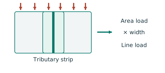
Prediction, then explanation. At fixed area load, twice the tributary width gives twice the line load. An end reaction remains a concentrated force.
Consider one metre along the beam. The associated floor area is b square metres. Multiply area load by that width.
q is area load in kN/m²; b is tributary width in m; w is line load in kN/m.
Scope. Determine b from slab spanning and supports. Add beam self-weight separately. A secondary-beam reaction is not automatically a UDL.
Check and takeaway. Illustration: . The width cancels one length unit.
Keep load categories separate
A floor carries permanent material and changing occupancy loads. Find the design load for the stated check.
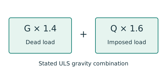
Prediction, then explanation. Increasing imposed load changes its own term. It does not change the dead-load factor or the steel stiffness.
First convert mass to weight where required. Next collect G and Q in compatible units. Apply the combination specified by the course problem.
G is characteristic dead load; Q is characteristic imposed load. Wu is the design load for this course gravity combination.
Scope. This combination is not universal. Use the specified service load for deflection and the stated factors for other standards or cases.
Check and takeaway. Illustration: G = 10 kN and Q = 5 kN give 22 kN. Factoring their sum by one guessed factor loses the distinction.
Balance the isolated beam
Find the two vertical reactions before calculating internal shear or moment.
Prediction, then explanation. Move the same load toward B. Reaction B increases because the load has a larger moment arm about A.
Take moments about A. Reaction A has zero lever arm there. Then use vertical force balance to find reaction A.
P, RA and RB are forces in kN. L is support spacing and a is load position, both in m.
Scope. These expressions describe one point load on a simply supported beam. Add other loads through equilibrium; keep their actual positions.
Check and takeaway. Illustration: P = 60 kN, L = 6 m and a = 2 m give RB = 20 kN and RA = 40 kN.
Apply the reasoning to this section’s data and conditions
First locate the columns and the vertical supports.
Mark the direction in which the one-way slab transfers load.
An interior beam receives half the adjacent bay on each side.
At an edge, include only the slab that actually transfers load to the beam.
Start with permanent load per slab area:
Multiplying slab thickness by unit weight gives load per area.
Finishes add another permanent load.
Next convert area load to beam load:
Add beam self-weight once.
Keep imposed load separate:
Convert the table mass per metre to self-weight using
The divisor converts newtons to kilonewtons.
For the stated gravity combination, apply to the separate characteristic loads.
A reaction calculated from factored loads is already a design reaction.
Applying the load factors again would count the same allowance twice.
For a simply supported beam with a full-span UDL, equilibrium gives and .
A central point load adds to each reaction and to the maximum moment.
Here is the support span.
For off-centre or multiple loads, first balance moments to find reactions.
Then calculate shear and moment separately in each load interval.
Use the selected section’s actual table row.
Its flange thickness determines the applicable design strength .
Calculate for the classification limits.
Check the flange and web separately; the more restrictive element determines the section class.
First calculate shear resistance: .
For the stated rolled-section major-axis case, uses web thickness and overall depth .
If and the section is Class 1 or 2, use .
Here and are plastic and elastic section moduli.
Above the shear threshold, use the specified high-shear reduction.
Where required, calculate web bearing with .
Here is stiff bearing length, is web thickness, and is web design strength.
The course defines and the end/internal factor for the contact detail.
Check web buckling separately using the applicable end-distance and restraint branch.
Without contact data, the local check remains incomplete.
For an imposed-load-only serviceability check, use unfactored .
The full-span UDL expression is .
The central point-load expression is .
Add contributions only when they use compatible elastic models and the same displacement location.
Compare the total with the specified finish or function limit.
Quick unit check: is measured in or has the same numerical value in these units; converts from to by ; converts from to by .
Do not use the midspan point-load formula for a load away from midspan.
Full reference example · Compulsory exam application
Mechanism detailsFollow the floor load in 3D
The complete mechanism is explained below.
Read each stage together with its stated conditions; playback and interaction are not required.
The floor carries pressure in .
The highlighted strip belongs to one secondary beam.
Multiply pressure by tributary width: .
The illustration uses .
- A primary beam receives the secondary beam reaction at their connection, not a new full-span UDL.
Trace reactions down to columns and foundations.
Count each loaded area once.
Revision sheet 2 · LTB decisions
Vertical bending can trigger sideways motion
A beam has enough local bending resistance. Check whether its compression flange can move sideways and twist.
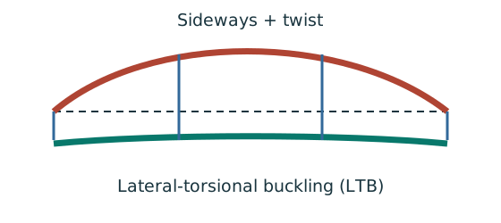
Prediction, then explanation. Adding a valid lateral restraint shortens a stability segment. It need not change the beam’s vertical reaction or moment diagram.
Identify the compressed flange and effective restraints. Calculate the specified slenderness, read buckling strength and compare resistance with the segment demand.
LE and ry use the same length unit. pb uses N/mm²; Sx uses mm³; Mb uses N·mm. mLT is dimensionless.
Scope. Use the specified section class, effective-length branch and loading condition. Load height alone does not prove a destabilizing case.
Check and takeaway. Removing a lateral restraint requires a new segment stability check. The old shorter-segment result cannot establish the longer segment’s adequacy.
Moment shape matters within one segment
Represent a nonuniform moment distribution in the applicable member-buckling equation.
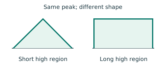
Prediction, then explanation. Two segments can have equal peak moment but different distributions. Their equivalent moment factors can therefore differ.
Evaluate moments from the true whole-beam analysis at the required positions. Apply the exact table’s weights, signs and lower bound.
mLT is an LTB factor. mx and my belong to the specified flexural checks. They are not interchangeable.
Scope. Some rules use magnitudes; others require signed ordinates. A factor does not reduce the actual moment used in a local section check.
Check and takeaway. Measure quarter points from the segment start, not automatically from the beam’s left support.
Move between two known values
The required slenderness lies between two table rows. Estimate the strength on the straight segment between those rows.
Prediction, then explanation. If the second strength is lower, moving toward that row must reduce the interpolated strength.
Subtract the lower input to find distance travelled. Divide by the input interval. Multiply that fraction by the output change.
x is the required input. The two known pairs are (x₀, y₀) and (x₁, y₁). f has no unit.
Scope. Use one table, curve and strength column. This interpolation does not permit extrapolation or inventing an intermediate steel section.
Check and takeaway. Illustration: between strengths 200 and 180, a fraction of 0.4 gives 192 N/mm². The result lies between both endpoints.
Apply the reasoning to this section’s data and conditions
Identify the compressed flange in each region.
Mark every effective lateral and torsional restraint.
Also state the load height: a load can have a destabilising effect when the beam twists.
Choose effective length from the applicable restraint condition.
A lateral restraint may shorten the buckling segment without supplying a vertical reaction.
Therefore, the vertical span and the unrestrained length may differ.
For each segment, first calculate .
This compares effective length with minor-axis radius of gyration.
Next calculate the section factor , using the course definition of .
Combine the factors in to obtain LTB slenderness.
Use only after establishing Class 1 or 2.
Use LTB slenderness and the correct design strength to enter Table 8.3a.
Interpolate the bending strength where necessary, then calculate .
Strength times section modulus gives moment in .
Divide by to obtain .
Calculate the moment factor from a matching standard moment diagram or the general absolute quarter-point expression.
Locate the quarter points within the current segment.
Whole-beam quarter points are incorrect when the segment covers only part of the beam.
Check for every potentially governing segment.
Separately check actual moment and shear .
A favourable moment factor in the stability check does not reduce the actual section demand.
An added lateral restraint changes the stability length.
The vertical-load bending moment diagram stays the same unless that restraint also acts as a new vertical support.
Keep these two roles separate when changing the model.
End-couple variant · Unequal segment loads
Mechanism detailsA beam bends sideways and twists
The complete mechanism is explained below.
Read each stage together with its stated conditions; playback and interaction are not required.
- For the illustrated sagging beam the top flange is compressed.
- The unrestrained compression flange can move sideways while the complete cross-section twists.
Only effective restraints divide the member into unbraced segments.
They do not automatically add vertical supports.
Use the segment effective length, section properties and matching moment factor.
This is an exaggerated mode shape, not a calculated displacement.
Revision sheet 3 · bolts and plates
A block leaves along two types of path
A connection can lose a block of plate without a single straight tensile fracture across the full width.
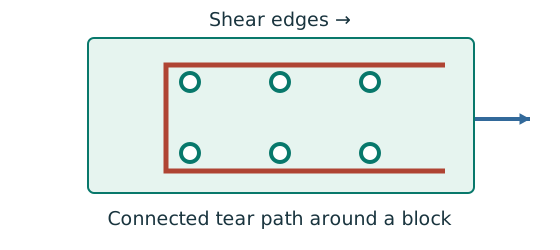
Prediction, then explanation. Changing the end distance changes the shear-path geometry. Adding plate width elsewhere may not strengthen the controlling block.
Draw the possible block first. Label shear and tension segments. Apply the course deductions and strength terms to their respective areas.
Shear and tension areas use mm². Their strength coefficients refer to different mechanisms and are not interchangeable.
Scope. Do not replace the supplied block-shear expression with the simple net-tension formula. Geometry and deductions depend on the actual path.
Check and takeaway. A complete path must release a block. A dashed line that does not enclose a removable piece is not that failure mechanism.
Add force components at each bolt
An in-plane load acts away from the bolt-group centre. Find the largest resultant bolt force.
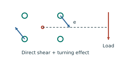
Prediction, then explanation. At fixed force, increasing eccentricity increases the moment component. Its direction differs between bolts.
Locate the bolt-group centre and coordinates. Add horizontal components together and vertical components together before finding each resultant.
e, xi and yi use mm; J uses mm². With M in kN·mm, each moment-force component is in kN.
Scope. These expressions use the stated elastic, equal-bolt in-plane model. Out-of-plane tension and prying require another model.
Check and takeaway. Do not add force magnitudes before resolving directions. Two perpendicular forces of 3 and 4 kN give 5 kN, not 7 kN.
An eccentric bracket pulls bolts differently
An out-of-plane moment rotates the bracket about the stated pivot. Determine the bolt tension pattern.
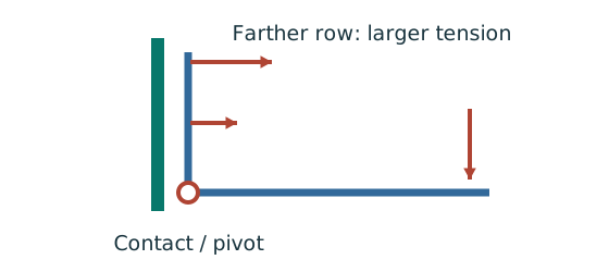
Prediction, then explanation. For unchanged geometry, doubling the applied moment doubles the modelled bolt tensions. Changing the pivot changes the distribution.
Use compatibility to relate tension to distance. Moment equilibrium then determines the proportionality factor.
M is moment in kN·mm. yi is distance from the stated pivot in mm. Ft,i is tension in kN.
Scope. Apply only to the stated active bolt set and pivot model. Flexible plates can create prying; use the supplied assumptions and resistance definitions.
Check and takeaway. A bolt’s lever arm is measured from the pivot used in the equation. It is not automatically its distance from the group centroid.
Apply the reasoning to this section’s data and conditions
A splice transfers the complete force into its covers and then out again.
Analyse one transfer half first.
Identify the plates and shear planes in that half.
For a concentric group of equivalent parallel bolts, divide the force by the bolt count in that transfer stage.
For each shear plane, bolt resistance is .
The shear strength multiplies the applicable resisting area .
Use thread or shank area according to the actual plane location.
The tension expressions are and .
The latter is the course nominal tension resistance; use it only in its specified interaction rule.
Calculate bolt bearing as .
Bolt diameter times contacted plate thickness gives projected contact area.
For two covers, compare the central contact resistance with the sum of the two outer contacts.
Those stages carry the same force.
For every connected part, compare the diameter-bearing bound with the end-bearing bound .
Also evaluate the specified bound .
Use the net hole ligament , plate thickness and the specified strengths .
Each part must resist its own allocated force; retain the smallest applicable resistance.
For plate tension, examine each plausible failure path through the holes.
Apply the specified effective-area factor and its cap.
For the applicable single or double bolted-angle case, include the respective reduction or .
These reductions represent incomplete participation of the unconnected leg.
For in-plane eccentricity, gives direct shear per bolt.
The eccentric force also gives moment .
Group geometry enters through , with coordinates measured from the bolt-group centroid.
Add the signed direct and torsional components along each axis.
Then find the resultant at every candidate critical bolt.
For out-of-plane bracket tension, use about the course pivot.
The row distance determines its tension contribution.
Confirm whether the stated prying assumptions apply.
Then check and the separate shear and tension limits.
Passing the interaction alone does not establish every connection check.
Finally check hole clearance, pitch, gauge, end distance and edge distance.
Include any requested block-shear, long-joint or grip adjustment.
These checks examine distinct failure or construction limits.
Adequate bolt shear resistance alone cannot establish the adequacy of the complete joint.
Full formulas and applicability · Every tabulated cell worked
Mechanism detailsSeparate the block-shear paths
The complete mechanism is explained below.
Read each stage together with its stated conditions; playback and interaction are not required.
- A block containing the connection can detach from the surrounding plate.
- The paths parallel to the applied force carry shear.
- The closing path across the end of the block carries tension.
Use the specified gross/net deductions and resistance expression.
This is different from a single straight net-section fracture.
Revision sheet 4 · welds
The weld resists through its throat
Convert a visible fillet leg into resistance per effective length.
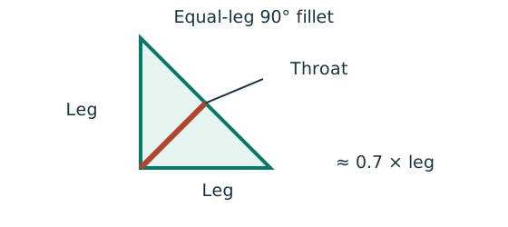
Prediction, then explanation. At fixed weld strength, doubling the leg doubles throat and line resistance in this model. Detailing limits can prevent that choice.
For the course right-angle equal-leg fillet, take throat as 0.7 times leg. Multiply throat area per unit length by weld strength.
s and a are leg and throat in mm. pw is weld strength in N/mm². qcap is resistance in kN/mm.
Scope. Use effective length, the correct steel/electrode strength and permitted leg limits. Full-penetration butt welds use a different model.
Check and takeaway. Illustration: a 6 mm leg at 250 N/mm² gives .
Unequal lever arms require unequal forces
Two longitudinal welds must transfer a tensile force through the angle centroid without an unintended moment.
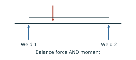
Prediction, then explanation. The weld with the shorter lever arm must carry more force to balance the longer-arm weld’s moment.
Use force balance and moment balance together. Then divide each force by its own line resistance to find required effective length.
P, F₁ and F₂ are forces. z₁ and z₂ are perpendicular distances from the load line. Use consistent length units.
Scope. Equal force shares apply only to the symmetric case. Physical terminated weld length also needs the supplied end deductions.
Check and takeaway. If the two lever arms become equal, the equations return equal forces. That limiting case checks the force distribution.
Treat a weld group as lines
An eccentric force creates direct line force and torsional line force in the same weld group.
Prediction, then explanation. Increasing eccentricity increases the torsional contribution. The governing corner depends on vector addition, not distance alone.
Find the line centroid. Integrate squared distance along the effective lines. Add direct and torsional components at every candidate critical point.
J is line polar inertia in mm³. x and y use mm. With M in kN·mm, q is line force in kN/mm.
Scope. A solid rectangle has area inertia in mm⁴ and is not this weld-line model. Missing weld sides change the centroid and integrals.
Check and takeaway. Compare the largest resultant line force with the selected throat resistance. Keep kN/mm distinct from total force in kN.
Apply the reasoning to this section’s data and conditions
First identify the parent steel and electrode combination to obtain the applicable weld strength.
For the course fillet weld, the effective throat is .
Capacity per unit length is .
The throat, rather than the visible leg, supplies the effective resisting area.
For a direct concentric force, total required effective length is .
Distribute that length among the actual parallel weld runs.
For each applicable terminated run, add to its effective length to obtain its physical length.
This end allowance does not add effective resistance.
For an unequal angle, use the tabulated centroid coordinates.
Force equilibrium fixes the total weld force.
Moment equilibrium about the section centroid fixes how that force divides between the two sides.
Unequal lever arms therefore require unequal force shares.
For an in-plane eccentric group, locate the weld-line centroid.
Calculate its polar line second moment in .
Direct force per length is , where is total effective line length.
The torsional components use and with the appropriate directions.
Add signed vectors at each candidate corner before comparing resultants.
For an out-of-plane flange/web model, use its stated rotation axis and resisting force couple.
The force directions differ from the in-plane centroidal model.
Select the model from the actual load direction before applying its equation.
Round a strength-derived size or length upward.
Then check the thicker-part minimum leg, thinner-edge maximum leg and minimum effective length.
Also check lap, returns and transverse spacing.
Increasing weld strength cannot make a geometrically invalid detail acceptable.
Complete the requested parent-metal, angle and cover-plate resistance checks.
If the minimum permitted leg exceeds the maximum permitted leg, no size satisfies both rules.
Redesign the detail instead of selecting a compromise size.
Rectangular group · A detailing conflict · Corrected splice
Mechanism detailsFrom fillet leg to effective throat
The complete mechanism is explained below.
Read each stage together with its stated conditions; playback and interaction are not required.
- An equal-leg fillet between perpendicular plates has an approximately right-triangular section.
For this geometry, throat .
It is shorter than the leg.
Effective resisting area = .
With here, capacity per length is .
- Use the course end allowances, minimum size and length rules; increasing the geometric length alone does not resolve every detailing check.
Revision sheet 5 · columns with bending
A strong cross-section can belong to an unstable member
A column carries axial compression and bending. Explain why more than one check is required.
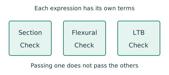
Prediction, then explanation. At fixed moments and resistances, increasing compression increases utilisation. A section pass cannot remove the length-dependent instability checks.
Separate cross-section, flexural-buckling and LTB interaction equations. Use each equation’s own denominators and first-order or amplified moments.
is a section axial resistance. is a member compression resistance. Elastic and prescribed are different bending denominators.
Scope. Preserve the course barred-moment definitions and Eq. 8.81 convention. Do not substitute plastic moduli into an elastic denominator.
Check and takeaway. Report each requested utilisation and the governing check. The largest properly calculated ratio identifies the closest limit.
Check buckling about both axes
Determine which buckling direction limits the compressed member.
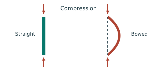
Prediction, then explanation. At fixed radius, longer effective length raises slenderness. The supplied buckling curve generally gives lower compressive strength.
Calculate slenderness about each axis. Select each axis’s curve from section type and thickness. Then obtain and compare the two compressive resistances.
Effective lengths and radii use mm. pc is compressive strength in N/mm²; Ag is gross area in mm²; Pc is in N.
Scope. Do not select the governing axis using radius alone. Effective length and buckling curve can differ. A combined column also needs interaction checks.
Check and takeaway. A short-section yield resistance is not the same as long-member buckling resistance. Keep py and pc distinct.
An eccentric beam reaction bends the column
A simple beam joint delivers a vertical reaction away from the column centre. Find the resulting column moments.
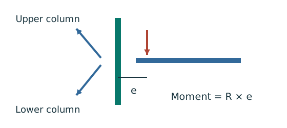
Prediction, then explanation. Equal opposite-face reactions can cancel a joint moment. Their downward forces still add to column compression.
Sum axial forces first. Calculate the signed eccentric moments. Share the net joint moment between upper and lower columns using the stated stiffness model.
R is reaction; e is perpendicular eccentricity. K denotes the stiffness measure prescribed for moment sharing.
Scope. Equal sharing requires equal stated stiffness. Use actual storey length where the special simple-construction LTB rule requires it.
Check and takeaway. A pin-like beam connection can still cause an eccentric reaction moment in the column. Joint rotation and reaction location are separate facts.
Apply the reasoning to this section’s data and conditions
First identify the frame model and end restraints.
These determine the effective lengths and .
For simple construction, derive the reactions and their eccentricities before distributing moments by column stiffness.
Use the exact UC section row and the thickness-dependent design strength .
Classify the elements under their combined compression and bending stresses.
A pure-bending web limit is not automatically applicable when axial compression is present.
The section interaction compares axial force with and moments with the prescribed capped section resistance .
Here is gross area.
Use the required amplified moments.
This checks section strength; member stability still needs its separate checks.
For each axis, calculate using its own effective length and radius of gyration.
Select the buckling curve from section type, thickness and axis.
Interpolate compressive strength , then calculate and .
Use where the stated equation requires the governing axial resistance.
The flexural member interaction uses elastic moment denominators .
Here is elastic section modulus.
Apply the lecture’s amplified moments with the corresponding factors and .
Do not substitute the plastic section resistance from the separate section check.
In course Eq. 8.81, the axial denominator is and the LTB resistance is .
Use the prescribed amplified together with the first-order minor-axis moment .
These moments have different definitions.
Do not amplify a second time.
For simple construction, apply the stated rule and .
Here is actual storey height.
The continuous/non-sway examples instead use and .
Choose the route from the frame model, rather than mixing factors from different examples.
All three requested interactions must pass because they represent different failure mechanisms.
Report the governing result and the model assumptions.
If an input remains uncertain, preserve that condition in the conclusion.
End-moment worked example · Simple-construction example
Mechanism detailsA strong slice can belong to an unstable member
The complete mechanism is explained below.
Read each stage together with its stated conditions; playback and interaction are not required.
- Combine axial compression and the two bending demands using the specified section resistances.
- The whole member adds effective-length and buckling-curve effects.
This uses its own moment factor and bending resistance.
It is not a copy of the section check.
Elastic, plastic and buckling resistances are not interchangeable.
Read the three original expressions and their first-order/amplified moments.
Revision sheet 6 · short theory that earns marks
Ask two separate design questions
Decide whether the check concerns failure or unacceptable behaviour during use.
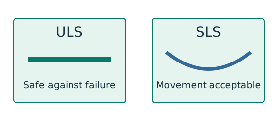
Prediction, then explanation. A larger section may improve both results, but a pass on one branch does not prove a pass on the other.
ULS addresses relevant strength and stability failure modes. SLS addresses specified service conditions such as deflection.
δ is the calculated displacement; δlimit is the permitted displacement. Both must use the same length unit.
Scope. Use each check’s own load combination and limit. A strength load factor does not change the physical stiffness.
Check and takeaway. Write separate conclusions for strength, stability and serviceability where requested. A single unexplained “safe” hides those distinctions.
Interrupt the corrosion process
Steel exposed to moisture and oxygen can lose material. Explain what each protection system does.
Prediction, then explanation. If a barrier coating is damaged, the exposed region can corrode. Zinc can also provide sacrificial protection where conditions permit.
Paint works mainly as a barrier. Galvanizing adds a zinc layer with barrier and sacrificial effects. Surface preparation affects performance.
No universal coating thickness or life follows from this mechanism sketch.
Scope. Weathering steel still needs suitable exposure and detailing. A protection label does not replace inspection or maintenance.
Check and takeaway. The useful comparison is the protection mechanism, exposure and maintenance need. Do not describe all coatings as identical barriers.
Delay heat reaching the steel
Identify how the protection surrounds a steel section. Then explain its purpose in a fire.
Prediction, then explanation. An insulating layer can slow heating. It does not mean the steel remains at room temperature indefinitely.
Heat changes steel behaviour. Protection delays that change by restricting heat transfer. Show the steel and protection boundaries separately.
The labelled boundaries describe geometry. They do not specify a tested fire-resistance rating.
Scope. Required thickness depends on the system, member and required rating. Do not infer thickness or minutes from a schematic.
Check and takeaway. For a sketch answer, distinguish all three shapes and state that protection delays steel heating.
Apply the reasoning to this section’s data and conditions
| Prompt | A concise explanatory answer |
|---|---|
| ULS versus SLS | ULS prevents strength/stability failure;SLS limits unacceptable deformation/vibration under the stated service actions. |
| Corrosion protection | Paint isolates steel from moisture/oxygen; galvanizing uses a zinc barrier plus sacrificial protection. |
| Fire protection | Solid casing,hollow casing andprofile casing reduce steel heating; draw the steel outline and protective layer. Do not invent a rating or thickness. |
| Four rolled shapes | Sketch and label UB,UC,channel,angle; showweb/flanges/legs distinctly. |
| First versussecond order | First order equilibrates loads on the original geometry; second order includes additional effects from displaced geometry under axial load. |
| Why section class matters | Local plate buckling limits available plasticity;class selects plastic,elastic or effective section resistance. |
| Why LTB can govern | The compression flange can move laterally and the beam twist despite adequate local bending/shear strength. |
| Why bolts andplates need checks | The joint can fail in a fastener or in the surrounding connected metal. The force must survive every transfer stage. |
Mechanism detailsTwo different design questions
The complete mechanism is explained below.
Read each stage together with its stated conditions; playback and interaction are not required.
- ULS compares factored actions with the applicable resistance to yielding, rupture or instability.
- SLS checks movement, vibration or another specified use requirement.
A beam can be strong enough but deflect too much.
The two checks need their own loads and denominators.
A resistance pass cannot stand in for a serviceability pass.
Complete all requested checks.
Sit the 120-minute mock
Use the same mechanism: Make the next decision from the known conditions. Changing a load value may preserve the method. Changing the support or failure mechanism can require a different method.
Apply the reasoning to this section’s data and conditions
A separate timer can support an optional timed attempt.
No timer is needed to study the solutions.
For an optional timed attempt, the paper requires two options selected during the reading period.
The reading edition keeps explanations available throughout.
All questions and marking suggestions are explicitly invented.
After marking, record first wrong decisions in the error log.
Repeat only after solving a changed question independently.
A high score obtained while copying a solution is not evidence that you can handle an unfamiliar variant.
Mechanism detailsFollow the calculation sequence
The complete mechanism is explained below.
Read each stage together with its stated conditions; playback and interaction are not required.
- Locate the load, supports, connection geometry and any stated assumptions.
- Keep given values, table lookups and calculated values distinct; reconcile their units.
- The calculation player steps through the existing expressions in their original order.
Compare demand with resistance or the relevant limit.
Keep missing inputs and conditional conclusions explicit.