Exam error checklist and source discrepancies
Use the first list before handing in an answer.
The second records actual differences in the supplied sources.
An independently derived correction is not an official marking scheme.
The last six minutes of an exam
Change the ruler, keep the quantity
A section table uses centimetres, but the strength calculation uses millimetres. The numbers must describe the same section.
Prediction, then explanation. Would every property increase by ten? No. The exponent determines how many factors of ten are needed.
First identify the physical quantity. Next convert each length factor. Keep force and length conversions separate when converting a moment.
Here n is the length exponent: 2 for area, 3 for section modulus and 4 for second moment of area.
Scope. Changing units changes neither the load nor the section. A conversion factor cannot repair a formula for the wrong physical quantity.
Check and takeaway. Illustration: . The fourth power belongs to the unit, not the number 2.
A table value has conditions
Find a design property without mixing a row, column or standard from a different case.
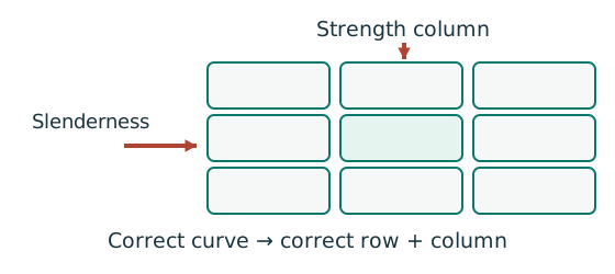
Prediction, then explanation. A different flange thickness can select a lower design strength even when the steel grade name remains unchanged.
Match the complete section designation. Read the relevant axis and unit. For strength tables, select material, thickness and curve before interpolating.
Given values come from the question. Lookup values come from a named table. Assumed values require an explicit condition.
Scope. A missing row or omitted restraint cannot be recovered from a schematic’s scale. Keep the result conditional when required data are absent.
Check and takeaway. Record the table, row, column and unit beside the substitution. That makes a later check possible.
Apply the reasoning to this section’s data and conditions
- Have I answered the compulsory question and exactly the required number of options, including every labelled subpart?
- Does each load carry its source and status: characteristic, already factored, calculated reaction or lookup self-weight?
Do reactions balance total load and moment?
Does the BMD close to zero at a simple support with no applied end couple?
- Have I used the exact section row, correct axis, thickness-dependent and -to- conversion?
- Have I separated low/high shear, section capacity, LTB, local web behaviour and deflection?
For bolts, did I count shear planes and transfer sides correctly?
For welds, did I use effective length and the correct centroid?
- For columns, did I use the correct curve per axis, correct moment sign, amplified versus first-order moment and correct denominator?
- Do dimensions come from labels or justified calculations, rather than scale measurements?
- Have I compared demand and resistance with units, stated pass/fail and named conditions that remain unverified?
Mechanism detailsFollow the calculation sequence
The complete mechanism is explained below.
Read each stage together with its stated conditions; playback and interaction are not required.
- Locate the load, supports, connection geometry and any stated assumptions.
- Keep given values, table lookups and calculated values distinct; reconcile their units.
- The calculation player steps through the existing expressions in their original order.
Compare demand with resistance or the relevant limit.
Keep missing inputs and conditional conclusions explicit.
Source discrepancies and how this site handles them
Use the same mechanism: A table value has conditions. A different flange thickness can select a lower design strength even when the steel grade name remains unchanged.
Use the same mechanism: Change the ruler, keep the quantity. Would every property increase by ten? No. The exponent determines how many factors of ten are needed.
Apply the reasoning to this section’s data and conditions
| Original source / location | Issue | Treatment and evidence |
|---|---|---|
| Syllabus p 4 versus Ch 1 p 7 and Data File footers | Syllabus cites 2011 (2023 Edition); supplied teaching/data identify 2011. | Use the supplied course equations and tables consistently; standards note. |
| Data File p 2, central point-load deflection | Prints , which has units rather than displacement. | Use , supported by Word note p 2 and 2023 Data 1; original correct equation. |
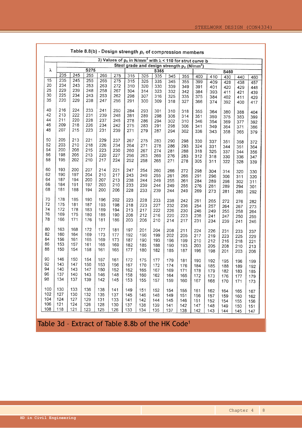
| Data File p 8, curve b / py 355 / λ90 | Cell prints . | Use , clearly shown in Ch 4 p 8, same row and column. |
| Data File p 3, compressed column equations | Bars and elastic moment denominators are not fully represented. | Use full lecture Eqs.8.80/8.81 and keep amplified/first-order moments distinct; full method. |
| Data File p 12, angle block | Some thickness labels are inconsistent with the area/property sequence. | 2024 angle question uses the stated // rectangular leg method; explicit derivation. Do not invent a corrected table row. |
| Ch 2 Example 1 pp 16–17 | Drawing shows four centre crosses; text and solution specify two bolts. | Follow the explicit two-bolt model and disclose the mismatch; worked solution. |
| Ch 2 Example 9 p 42 | Side Y text says add but its arithmetic adds for a fillet. | Correct deduction ; final physical lengths / remain; derivation. |
| Ch 2 Example 10 pp 43–44 versus minimum-size table p 33 | Selected fillet joins a main plate; supplied minimum table requires . | Preserve lecture trial, then design an alternative with runs and returns; checked dimensions. |
| Chapter 2 Tutorial 5, pp.45/47 | angle and gusset give maximum edge leg but minimum leg . | No size satisfies both supplied rules; show the conflict and required redesign, not a fictitious passing detail; solution. |
| Ch 3 Example 4 p 31 | Names a UB. | Listed properties match supplied row; solution uses that row. |
| Ch 4 Example 3 pp 29–30 | Amplified moment appears as after a calculation. | Use consistent unrounded moment from exact loads, or if retaining lecturer rounded ; derivation. |
| Ch 4 Example 5 p 38 | Rounded interaction terms sum to printed . | Unrounded sum is about , rounding to ; pass unchanged; calculation. |
| Assignment 2 heading and Q1 | Filename/header/figure identifiers conflict; key text sentence is clipped from rendered paragraph. | Use the supplied text-layer section/length data explicitly; original figures retained; source note. |
| 2024 paper, six supplied pages | Mentions an 18-page data attachment that is not included. | Use identified standalone/2023 supplied lookups; missing attachment is not fabricated; paper navigator. |
| Small rounding differences in lecture tables/examples | Some cells truncate or use rounded intermediate capacities. | Recalculate from printed input areas, keep guard digits and distinguish rounding from changed assumptions; every table cell. |
Mechanism detailsFollow the calculation sequence
The complete mechanism is explained below.
Read each stage together with its stated conditions; playback and interaction are not required.
- Locate the load, supports, connection geometry and any stated assumptions.
- Keep given values, table lookups and calculated values distinct; reconcile their units.
- The calculation player steps through the existing expressions in their original order.
Compare demand with resistance or the relevant limit.
Keep missing inputs and conditional conclusions explicit.
Conditions that cannot be verified from a sketch alone
A concentrated force spreads into the web
Check local web resistance at a support or concentrated load, even if overall beam strength passes.
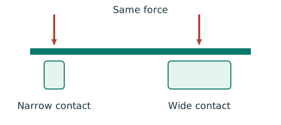
Prediction, then explanation. A longer valid stiff-bearing length can spread the same force over more web. A flexible contact is not automatically stiff bearing.
Match the actual bearing geometry to its source sketch. Use that sketch’s dimensions and permitted spread to calculate the resisting region.
b₁ is stiff-bearing length in mm. Web thickness and applicable design strength enter the prescribed local resistance equation.
Scope. End and interior cases can differ. A lateral-restraint symbol does not provide a bearing length or a load-introduction detail.
Check and takeaway. If bearing geometry is missing, give the applicable symbolic check and state the missing input. Do not borrow another example’s dimensions.
An eccentric bracket pulls bolts differently
An out-of-plane moment rotates the bracket about the stated pivot. Determine the bolt tension pattern.
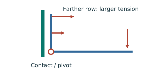
Prediction, then explanation. For unchanged geometry, doubling the applied moment doubles the modelled bolt tensions. Changing the pivot changes the distribution.
Use compatibility to relate tension to distance. Moment equilibrium then determines the proportionality factor.
M is moment in kN·mm. yi is distance from the stated pivot in mm. Ft,i is tension in kN.
Scope. Apply only to the stated active bolt set and pivot model. Flexible plates can create prying; use the supplied assumptions and resistance definitions.
Check and takeaway. A bolt’s lever arm is measured from the pivot used in the equation. It is not automatically its distance from the group centroid.
A bolt diameter is not a hole diameter
Check that bolts fit and leave enough material between holes and plate boundaries.
Prediction, then explanation. At fixed pitch, a larger hole leaves a shorter clear ligament. Increasing bolt diameter may also increase minimum edge-distance requirements.
Measure pitch along the bolt line and gauge across lines. Distinguish end distance along the load from edge distance across it.
lc is clear ligament between holes; p is centre-to-centre pitch; d₀ is hole diameter. All use mm.
Scope. Apply the supplied edge-preparation and minimum/maximum spacing rules. Passing a bearing calculation does not prove the layout passes.
Check and takeaway. For pitch 60 mm and hole diameter 22 mm, the ligament is 38 mm. Using a 20 mm bolt diameter here gives the wrong ligament.
Apply the reasoning to this section’s data and conditions
The coverage checklist records affected items as incomplete when a requested final detail needs absent input.
Examples include local bearing/contact lengths, missing plate thickness for a weld-size limit, unknown transverse bolt gauge for no-prying applicability, and an unstated LTB load-height/end-restraint model.
A conditional calculation is still useful teaching, but it is not an unconditional certification.
Read the item-by-item blockers.
All original files remain unchanged.
The website’s illustration for the AI-sketch assignment is authored teaching material.
It is not a fabricated student conversation screenshot.
Mechanism detailsFollow the calculation sequence
The complete mechanism is explained below.
Read each stage together with its stated conditions; playback and interaction are not required.
- Locate the load, supports, connection geometry and any stated assumptions.
- Keep given values, table lookups and calculated values distinct; reconcile their units.
- The calculation player steps through the existing expressions in their original order.
Compare demand with resistance or the relevant limit.
Keep missing inputs and conditional conclusions explicit.
A better error log
Make the next decision from the known conditions
Read the specific task below and identify the quantity or explanation it asks for.
Prediction, then explanation. Changing a load value may preserve the method. Changing the support or failure mechanism can require a different method.
Separate given, lookup, calculated and assumed values. State why the model applies. Keep necessary intermediate steps and units beside the equations.
A conditional answer states the exact condition required for its conclusion. It does not fill missing data with a guess.
Scope. A repeated result is not an independent verification. Use equilibrium, dimensions, a reverse substitution or an appropriate limiting case.
Check and takeaway. The explanation and answer are shown together in this edition. No response, score or completed interaction is needed to continue.
Apply the reasoning to this section’s data and conditions
| Record | Example |
|---|---|
| First incorrect decision | I used the full dimension rather than the support-to-support B2 span. |
| Evidence I missed | A column symbol occurs on the middle grid line. |
| Repair | Draw only one free-body span; label each support before transferring loads. |
| Independent retest | Solve the 2024 floor variant with altered slab load and no open solution. |
Prediction and explained answer.
Why is “I made an arithmetic mistake” too vague after a wrong LTB result?
Answer and reasoning
The first error may be choosing full span instead of restraint spacing, using the wrong unit, or reading rather than .
Identify the first wrong decision so the next unfamiliar problem is solved correctly.
Mechanism detailsFollow the calculation sequence
The complete mechanism is explained below.
Read each stage together with its stated conditions; playback and interaction are not required.
- Locate the load, supports, connection geometry and any stated assumptions.
- Keep given values, table lookups and calculated values distinct; reconcile their units.
- The calculation player steps through the existing expressions in their original order.
Compare demand with resistance or the relevant limit.
Keep missing inputs and conditional conclusions explicit.