2024 BQ2(a): back-to-back bolted angles
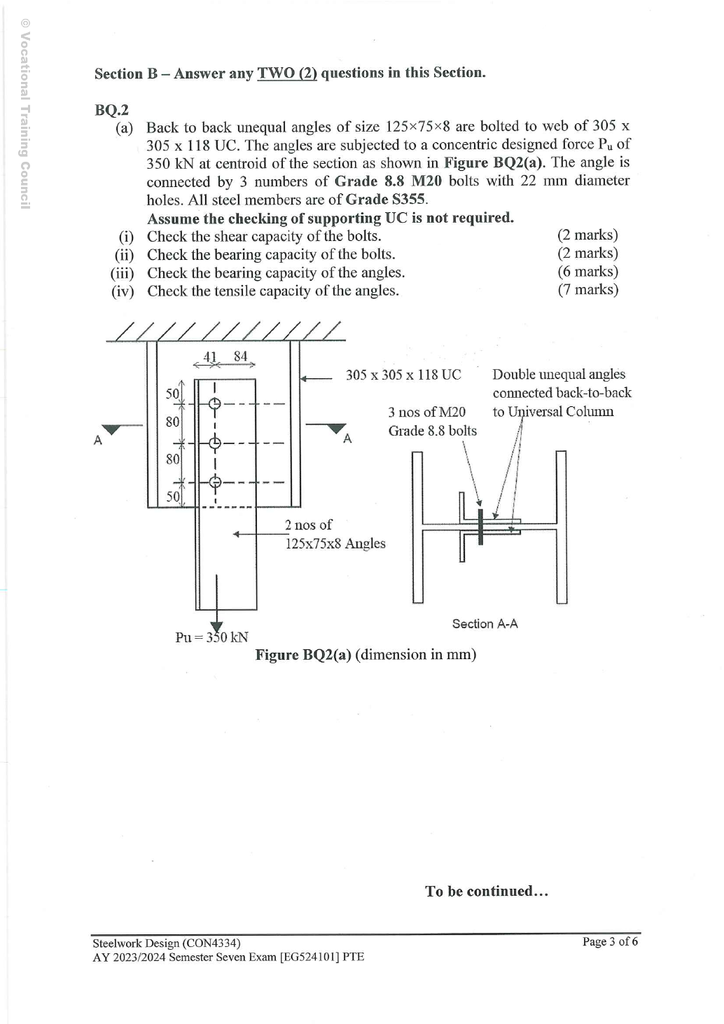
Check bolt shear, bolt bearing, angle bearing and angle tension for two S355 unequal angles connected back-to-back to the web of UC by threeM20 Grade 8.8 bolts in holes. Design concentric tension is . The paper excludes checking the supporting UC.
Original source: Pastpaper/23ENGTY004.pdf — p. 3.
A given value comes from the question or diagram.
A lookup value comes from the named table.
A calculated value follows from the working.
Each assumption is stated where the calculation needs it.
Known information, diagram labels and unknowns
Follow contact pressure into the plate
The bolt may survive shear while the connected plate deforms or tears near the hole.
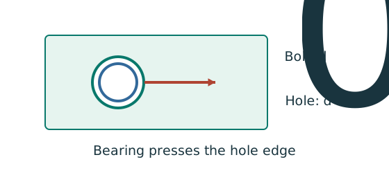
Prediction, then explanation. At fixed geometry and strength, a thicker plate raises plate resistance. Moving a hole too near the end can still govern.
Calculate every bound required by the supplied rule. The smallest applicable bound limits the connection at that layer.
pbs is the applicable bearing strength in N/mm²; d is nominal bolt diameter in mm; t is plate thickness in mm.
Scope. This diameter term alone is not the complete check. End-distance and clear-ligament limits, bolt bearing and each connected layer also matter.
Check and takeaway. Two covers and one main plate do not necessarily have the same thickness or strength. Compare the actual force share in each layer.
One connected leg does not load both legs equally
An angle carries tension through only one leg. Determine how much section area the design rule permits.
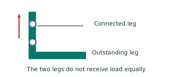
Prediction, then explanation. Keeping the same gross area does not guarantee the same tension resistance when the connection arrangement changes.
Separate connected and outstanding leg areas. Include the actual holes. Then use the supplied single-angle or double-angle effective-area rule.
Ae is the effective area from the applicable angle rule in mm². py is the relevant design strength in N/mm².
Scope. Do not assume the whole gross area is effective. Symmetry, connected leg and connection type determine which rule applies.
Check and takeaway. The outstanding leg contributes through load transfer; the rule need not either count all of it or discard all of it.
A table value has conditions
Find a design property without mixing a row, column or standard from a different case.
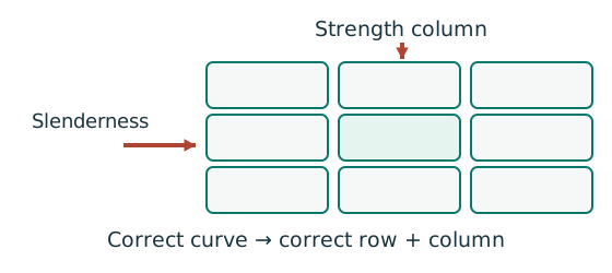
Prediction, then explanation. A different flange thickness can select a lower design strength even when the steel grade name remains unchanged.
Match the complete section designation. Read the relevant axis and unit. For strength tables, select material, thickness and curve before interpolating.
Given values come from the question. Lookup values come from a named table. Assumed values require an explicit condition.
Scope. A missing row or omitted restraint cannot be recovered from a schematic’s scale. Keep the result conditional when required data are absent.
Check and takeaway. Record the table, row, column and unit beside the substitution. That makes a later check possible.
Apply the reasoning to this section’s data and conditions
| Input | Source/type |
|---|---|
| Force | Given ultimatePu 350 kN, symmetric pair → per angle. |
| Bolt material | M20 ; Grade 8.8 , , . |
| Central ply | Data File p.11, UC web . Read the web column, not flange . |
| Angle material | S355 →py 355; coursepbs 550,Us 510,Ke 1.1. |
| Area model | Use exact given // rectangular leg split as in the lecture. The current unequal-angle table has a mislabelled thickness row. Do not import its inconsistent area as an angle. |
Why this method applies
Count cuts through each loaded bolt
Find how many shear planes transfer the force through one side of the connection.
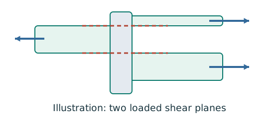
Prediction, then explanation. For equal sharing and unchanged bolt area, two active planes provide twice one plane’s shear resistance.
Select the area at the actual shear plane. Multiply by bolt shear strength. Count only the bolts and planes in the same transfer stage.
ps is bolt shear strength in N/mm²; As is the appropriate area in mm². nb counts bolts; ns counts equally loaded shear planes.
Scope. Use the thread area when threads cross the plane as required. Check bearing, plate failure and detailing separately.
Check and takeaway. Both halves of a butt splice carry the full transmitted force in sequence. Counting both halves together would double the apparent resistance.
Use the same mechanism: One connected leg does not load both legs equally. Keeping the same gross area does not guarantee the same tension resistance when the connection arrangement changes.
Apply the reasoning to this section’s data and conditions
The section view determines the number of shear planes.
Follow through three bolts into two angle legs, allocating to each angle.
For angle tension, deduct one hole on a transverse fracture path, apply effective-area caps and then the double-bolted-angle shear-lag reduction.
(i) Bolt shear —2 printed marks
Use the same mechanism: Count cuts through each loaded bolt. For equal sharing and unchanged bolt area, two active planes provide twice one plane’s shear resistance.
Apply the reasoning to this section’s data and conditions
Physical interpretation: Count where the bolt can be sheared
The plate interfaces are the places trying to cut across the bolt.
Sketch, not to scale; use the original dimensions.
- Count actual loaded shear planes, not merely visible plates.
- Choose shank or threaded area for the plane concerned.
- Compare group resistance with the force that group transfers.
Remember: Bolts on opposite sides of a splice do not all act in parallel.
Mechanism detailsCount the bolt shear planes
The complete mechanism is explained below.
Read each stage together with its stated conditions; playback and interaction are not required.
- Load must cross an interface between the connected plates.
- A lap joint gives one shear plane through a bolt.
A symmetric double-cover joint may provide two shear planes.
Count load-transfer interfaces, not just visible plates.
Use the source’s area and shear strength.
Then check bearing, plate resistance and detailing separately.
(ii) Bolt bearing —2 printed marks
Use the same mechanism: Follow contact pressure into the plate. At fixed geometry and strength, a thicker plate raises plate resistance. Moving a hole too near the end can still govern.
Apply the reasoning to this section’s data and conditions
Physical interpretation: The bolt can crush or tear the plate
A strong bolt can still push through a weak hole edge.
Sketch, not to scale; use the original dimensions.
- Check the bolt and each connected plate’s bearing bounds.
- Use nominal bolt diameter for bearing; hole size for removed material.
- The smallest applicable resistance controls.
Remember: A short end distance may govern even when bolt shear passes.
Each outer contact individually provides against .
The paired exceeds the central .
This checks the bolt bearing limit.
It does not perform the expressly excluded UC material-bearing or web-strength design.
Mechanism detailsBearing and the remaining ligament
The complete mechanism is explained below.
Read each stage together with its stated conditions; playback and interaction are not required.
- Force transfers through contact between bolt and connected plate.
The plate around the hole carries bearing stress.
Bolt bearing and plate bearing are separate checks.
A short ligament can tear out towards the end.
The direction of force determines the relevant edge.
- Evaluate every specified bearing and ligament bound for each layer and retain the smallest applicable resistance.
(iii) Bearing of the angles —6 printed marks
Use the same mechanism: Follow contact pressure into the plate. At fixed geometry and strength, a thicker plate raises plate resistance. Moving a hole too near the end can still govern.
Apply the reasoning to this section’s data and conditions
Evaluate one angle under .
Use d 20 for projected bearing, d₀22 for ligament deductions, pitch and end .
The ordinary-hole factor .
Optional detailing observation, beyond the four requested strength checks: the closest transverse edge exceeds either M20 minimum /.
The opposite free-edge distance exceeds the ordinary maximum, so a complete detail would require review of that provision.
It does not change the arithmetic bearing result above.
Mechanism detailsBearing and the remaining ligament
The complete mechanism is explained below.
Read each stage together with its stated conditions; playback and interaction are not required.
- Force transfers through contact between bolt and connected plate.
The plate around the hole carries bearing stress.
Bolt bearing and plate bearing are separate checks.
A short ligament can tear out towards the end.
The direction of force determines the relevant edge.
- Evaluate every specified bearing and ligament bound for each layer and retain the smallest applicable resistance.
(iv) Tensile capacity of the angles —7 printed marks
Test every possible fracture cut
Find the remaining steel area across a candidate tension-failure path.
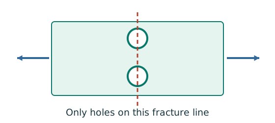
Prediction, then explanation. At fixed plate size, larger holes reduce the straight-path net area. A diagonal path needs its own stagger correction.
Subtract the hole widths crossed by the path, then multiply by thickness. Compare all plausible paths using the applicable course rule.
An is net area in mm²; b is plate width; d₀ is hole diameter; t is thickness, all in mm. n counts holes on this straight path.
Scope. This expression is for a straight cut. Effective area can require further shear-lag rules. Gross, net and effective areas must remain distinct.
Check and takeaway. Use the hole diameter, not the bolt diameter, when removing missing steel. The plate contains a hole, not solid steel around the bolt shank.
Use the same mechanism: One connected leg does not load both legs equally. Keeping the same gross area does not guarantee the same tension resistance when the connection arrangement changes.
Apply the reasoning to this section’s data and conditions
Physical interpretation: One connected leg does not load both legs equally
The connected leg receives the pull first.
The other leg receives it through the angle.
Sketch, not to scale; use the original dimensions.
- Identify connected and outstanding legs from the drawing.
- Use the relevant bolted or welded angle rule.
- Keep the lecturer’s area convention consistent.
Remember: Bolted and welded reduction expressions are not the same rule.
The connected leg contains the hole.
The outstanding leg does not.
Split the shared heel equally so no area is counted twice.
As in the lecture, applyKe to the connected net leg and cap the unconnected leg at its gross area.
The fracture path cuts one of the three longitudinally aligned holes.
Deducting all three from the same transverse section is incorrect.
Conversely, multiplying the outstanding by without its cap would invent extra gross area.
Among the requested pair/group resistances, angle bearing is the lowest.
Mechanism detailsSubtract holes on the failure path
The complete mechanism is explained below.
Read each stage together with its stated conditions; playback and interaction are not required.
- Gross area counts the complete plate width and thickness.
- The highlighted transverse path passes through the bolt holes.
For the straight illustrative path, .
Staggered paths require their specified correction.
Net area is not always effective area.
Include the course’s strength ratio or shear-lag rule when applicable.
Result and concise exam wording
Use the same mechanism: Count cuts through each loaded bolt. For equal sharing and unchanged bolt area, two active planes provide twice one plane’s shear resistance.
Use the same mechanism: Follow contact pressure into the plate. At fixed geometry and strength, a thicker plate raises plate resistance. Moving a hole too near the end can still govern.
Use the same mechanism: One connected leg does not load both legs equally. Keeping the same gross area does not guarantee the same tension resistance when the connection arrangement changes.
Apply the reasoning to this section’s data and conditions
Pu 350 kN; per angle.
ThreeM20 in double shear:.
Bolt bearing with centralUCweb :.
Angle bearing: perbolt perangle, pair .
Angle effective area less gives ; pair tensile .
All four requested strength checks pass; supporting UC strength excluded.
Full detailing still needs the edge-distance provision reviewed.
Misconceptions and checks
Use the same mechanism: Test every possible fracture cut. At fixed plate size, larger holes reduce the straight-path net area. A diagonal path needs its own stagger correction.
Use the same mechanism: A table value has conditions. A different flange thickness can select a lower design strength even when the steel grade name remains unchanged.
Apply the reasoning to this section’s data and conditions
- Do not take the UC flange thickness when the bolt passes through its web.
- Do not confuse two angles with six physical bolts.
- Deduct one hole from the transverse angle net section.
- Use the double-bolted coefficient , not the single-bolted .
How the method transfers to a new variant
Use the same mechanism: One connected leg does not load both legs equally. Keeping the same gross area does not guarantee the same tension resistance when the connection arrangement changes.
Use the same mechanism: A table value has conditions. A different flange thickness can select a lower design strength even when the steel grade name remains unchanged.
Apply the reasoning to this section’s data and conditions
- Read sectionA–A before counting interfaces.
- Allocate the total force to bolts and angle legs.
- Compare central and combined outer contact thicknesses.
- Compute all angle-bearing bounds.
- Build capped effective leg areas and apply the connection-specific reduction.
Prediction with explained answer
Use the same mechanism: Count cuts through each loaded bolt. For equal sharing and unchanged bolt area, two active planes provide twice one plane’s shear resistance.
Use the same mechanism: Follow contact pressure into the plate. At fixed geometry and strength, a thicker plate raises plate resistance. Moving a hole too near the end can still govern.
Use the same mechanism: One connected leg does not load both legs equally. Keeping the same gross area does not guarantee the same tension resistance when the connection arrangement changes.
Apply the reasoning to this section’s data and conditions
Prediction and explained answer.
Invented variant: increasePu to .
Which of the four requested strength modes first fails?
Answer and reasoning
Angle bearing is and fails.
Bolt shear551.25 kN is a very narrow pass; bolt bearing720 and angle tension921.012 remain higher.
The joint cannot be accepted just because the bolt shear still passes.
Mechanism detailsCount the bolt shear planes
The complete mechanism is explained below.
Read each stage together with its stated conditions; playback and interaction are not required.
- Load must cross an interface between the connected plates.
- A lap joint gives one shear plane through a bolt.
A symmetric double-cover joint may provide two shear planes.
Count load-transfer interfaces, not just visible plates.
Use the source’s area and shear strength.
Then check bearing, plate resistance and detailing separately.