Timed mock: questions only
This entire mock, its diagrams, model answers and mark scheme are invented teaching material.
It follows the supplied two-hour format.
It is not an official paper or a prediction.
Answer Q1 ( marks) and any TWO of Q2/Q3/Q4 ( marks each).
Total required marks.
Use the supplied local data tables and a calculator.
Do not reveal answers until the minutes end.
All steel is S355.
.
Use the supplied HK course methods, not a different standard.
Where loads are marked “design”, they are already factored.
Suggested time: read/select min; Q1 min.
Each option min; final check min.
Q1 · compulsory ·40 marks
Follow one strip of floor
An area load must become a beam load before beam reactions can be calculated.
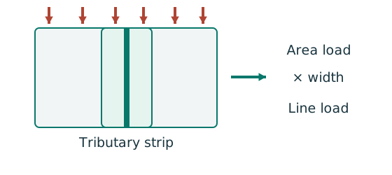
Prediction, then explanation. At fixed area load, twice the tributary width gives twice the line load. An end reaction remains a concentrated force.
Consider one metre along the beam. The associated floor area is b square metres. Multiply area load by that width.
q is area load in kN/m²; b is tributary width in m; w is line load in kN/m.
Scope. Determine b from slab spanning and supports. Add beam self-weight separately. A secondary-beam reaction is not automatically a UDL.
Check and takeaway. Illustration: . The width cancels one length unit.
Apply the reasoning to this section’s data and conditions
Reinforced-concrete slab thickness , unit weight .
Finishes add , and the imposed load is .
In plan, three transverse B1 beams bound two slab bays, each spanning .
Each B1 spans onto the B2 edge beams drawn vertically in the plan.
Each B2 spans between corner columns.
The middle B1 connects at its midspan.
Design the middle B1 and one B2.
B1 is UB (tabulated mass ); B2 is UB ().
Use .
Both are simply supported, fully laterally restrained by the slab, and carry brittle finishes.
Do not assume composite stiffness.
The requested scope is shear, bending and imposed-load deflection; local connection/web-contact design is not required.
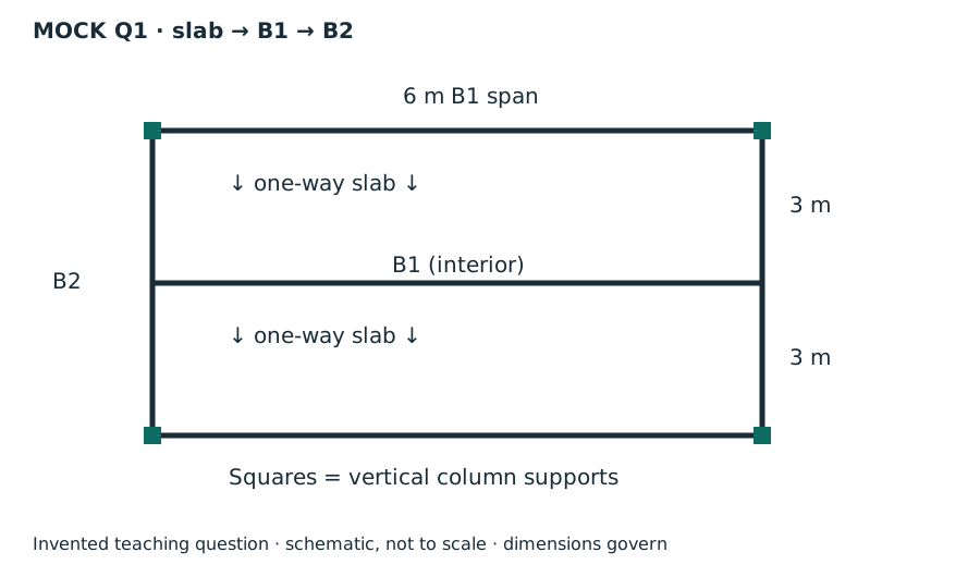
Invented mock-question diagram.
Slab → B1 → B2 shows slab load passing first to B1, then B2.
The slab spans one way; interior denotes an internal beam.
Squares mark corner columns providing vertical support.
B1 spans .
The two slab spans on the right are each .
Schematic, not to scale; stated dimensions govern.Open full-size image.
(a) Calculate characteristic dead and ultimate slab intensity.
[4]
(b) Calculate both beam design load models, reactions and maximum moments.
[8]
(c) Classify both sections.
[4]
(d) Check B1 shear, bending and imposed-load deflection.
[10]
(e) Check B2 shear, bending and imposed-load deflection.
[10]
(f) Explain two differences between strength and stiffness.
[4]
Mechanism detailsFollow the floor load in 3D
The complete mechanism is explained below.
Read each stage together with its stated conditions; playback and interaction are not required.
The floor carries pressure in .
The highlighted strip belongs to one secondary beam.
Multiply pressure by tributary width: .
The illustration uses .
- A primary beam receives the secondary beam reaction at their connection, not a new full-span UDL.
Trace reactions down to columns and foundations.
Count each loaded area once.
Q2 · optional ·30 marks
Count cuts through each loaded bolt
Find how many shear planes transfer the force through one side of the connection.
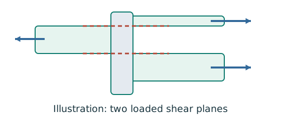
Prediction, then explanation. For equal sharing and unchanged bolt area, two active planes provide twice one plane’s shear resistance.
Select the area at the actual shear plane. Multiply by bolt shear strength. Count only the bolts and planes in the same transfer stage.
ps is bolt shear strength in N/mm²; As is the appropriate area in mm². nb counts bolts; ns counts equally loaded shear planes.
Scope. Use the thread area when threads cross the plane as required. Check bearing, plate failure and detailing separately.
Check and takeaway. Both halves of a butt splice carry the full transmitted force in sequence. Counting both halves together would double the apparent resistance.
Follow contact pressure into the plate
The bolt may survive shear while the connected plate deforms or tears near the hole.
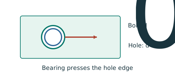
Prediction, then explanation. At fixed geometry and strength, a thicker plate raises plate resistance. Moving a hole too near the end can still govern.
Calculate every bound required by the supplied rule. The smallest applicable bound limits the connection at that layer.
pbs is the applicable bearing strength in N/mm²; d is nominal bolt diameter in mm; t is plate thickness in mm.
Scope. This diameter term alone is not the complete check. End-distance and clear-ligament limits, bolt bearing and each connected layer also matter.
Check and takeaway. Two covers and one main plate do not necessarily have the same thickness or strength. Compare the actual force share in each layer.
Test every possible fracture cut
Find the remaining steel area across a candidate tension-failure path.
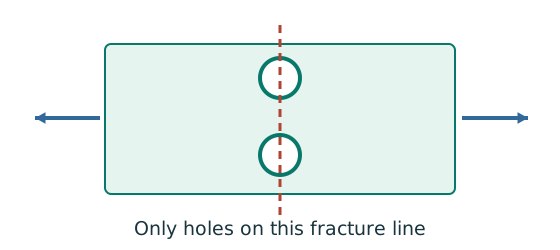
Prediction, then explanation. At fixed plate size, larger holes reduce the straight-path net area. A diagonal path needs its own stagger correction.
Subtract the hole widths crossed by the path, then multiply by thickness. Compare all plausible paths using the applicable course rule.
An is net area in mm²; b is plate width; d₀ is hole diameter; t is thickness, all in mm. n counts holes on this straight path.
Scope. This expression is for a straight cut. Effective area can require further shear-lag rules. Gross, net and effective areas must remain distinct.
Check and takeaway. Use the hole diameter, not the bolt diameter, when removing missing steel. The plate contains a hole, not solid steel around the bolt shank.
Apply the reasoning to this section’s data and conditions
(a) A300 kN design tension is transferred by a symmetric double-cover splice.
Main plate , two covers each, width throughout.
There are fourM20 Grade 8.8 bolts on each side of the butt, in two lines and two longitudinal rows.
Standard holes .
Along each half: main end distance , pitch .
Each cover extends beyond the outer bolt centre.
Gauge and transverse edges .
All edges are rolled.
Threads cross both shear planes.
Check bolt shear and bolt bearing, main/cover connected-part bearing and net tension, and spacing.
UseKe 1.1,pbs 550,Us 510,Ub 800.
Supporting members and block-shear paths are outside the requested scope.
[18]
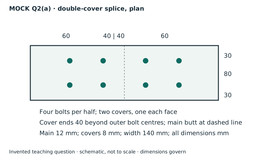
Invented mock-question diagram: double-cover splice in plan.
Four bolts per half, with one cover plate on each main-plate face.
The dashed line is the main-plate butt joint.
Each nearest bolt centre is from the joint.
Longitudinal pitch .
The cover plate projects beyond the outermost bolt centre.
Transverse dimensions , , .
Main-plate thickness ; cover-plate thickness ; width .
All diagram dimensions are in .
Not to scale; dimension labels govern.Open full-size image.
(b) A continuous closed rectangular fillet-weld line wide by high carries a design downward force whose line is right of the weld centroid.
Plate thicknesses and ; S355/Class 42 electrode.
Treat the given rectangle as the effective line.
Calculate the governing corner line force and choose a fillet leg satisfying strength and the supplied minimum/maximum size rules.
[]
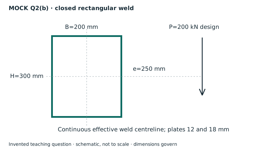
Invented mock-question diagram: closed rectangular weld.
is width.
is height; dashed lines intersect at the centroid.
The downward design force acts at eccentricity from the centroid.
Green lines are the continuous effective weld centrelines.
Plate thickness and .
Not to scale; stated dimensions govern.Open full-size image.
Mechanism detailsCount the bolt shear planes
The complete mechanism is explained below.
Read each stage together with its stated conditions; playback and interaction are not required.
- Load must cross an interface between the connected plates.
- A lap joint gives one shear plane through a bolt.
A symmetric double-cover joint may provide two shear planes.
Count load-transfer interfaces, not just visible plates.
Use the source’s area and shear strength.
Then check bearing, plate resistance and detailing separately.
Q3 · optional ·30 marks
Check buckling about both axes
Determine which buckling direction limits the compressed member.
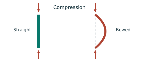
Prediction, then explanation. At fixed radius, longer effective length raises slenderness. The supplied buckling curve generally gives lower compressive strength.
Calculate slenderness about each axis. Select each axis’s curve from section type and thickness. Then obtain and compare the two compressive resistances.
Effective lengths and radii use mm. pc is compressive strength in N/mm²; Ag is gross area in mm²; Pc is in N.
Scope. Do not select the governing axis using radius alone. Effective length and buckling curve can differ. A combined column also needs interaction checks.
Check and takeaway. A short-section yield resistance is not the same as long-member buckling resistance. Keep py and pc distinct.
Apply the reasoning to this section’s data and conditions
A braced, non-sway UC carries design compression .
Effective length about both axes is .
Uniform first-order moments act about the axes as follows: axis by and about axis by .
The amplification factor for each axis is .
A separate equivalent amplified major-axis LTB moment is given as .
All moment factors .
Use exact , and the course non-sway expressions. (a) Section classification [4]; (b) cross-section interaction [6]; (c) both member-buckling interaction checks [20].
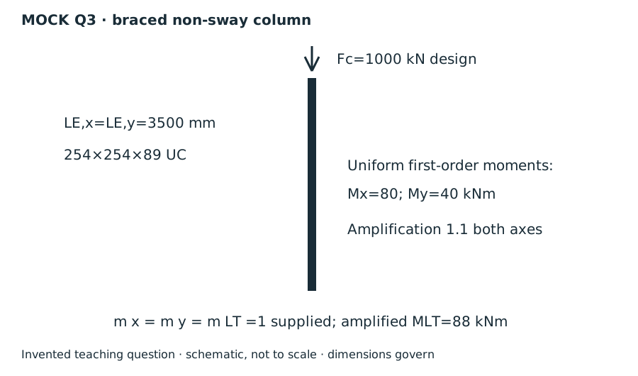
Invented mock-question diagram: braced non-sway column.
The top arrow denotes design compression .
Section UC; effective lengths about the two axes .
Uniform first-order moments , ; amplification factors about the two axes .
Given and already amplified .
Schematic, not to scale; numerical labels govern.Open full-size image.
Mechanism detailsEffective length and buckling axes
The complete mechanism is explained below.
Read each stage together with its stated conditions; playback and interaction are not required.
- A column can bow sideways before its section reaches the crushing resistance.
- Each axis has its own radius of gyration and restraint spacing.
, with compatible length units.
A tie affects only the directions it actually restrains.
Select each buckling curve and compressive strength before forming Pc.
The governing axis is determined by resistance, not slenderness alone.
Q4 · optional ·30 marks
Vertical bending can trigger sideways motion
A beam has enough local bending resistance. Check whether its compression flange can move sideways and twist.
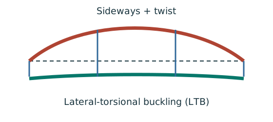
Prediction, then explanation. Adding a valid lateral restraint shortens a stability segment. It need not change the beam’s vertical reaction or moment diagram.
Identify the compressed flange and effective restraints. Calculate the specified slenderness, read buckling strength and compare resistance with the segment demand.
LE and ry use the same length unit. pb uses N/mm²; Sx uses mm³; Mb uses N·mm. mLT is dimensionless.
Scope. Use the specified section class, effective-length branch and loading condition. Load height alone does not prove a destabilizing case.
Check and takeaway. Removing a lateral restraint requires a new segment stability check. The old shorter-segment result cannot establish the longer segment’s adequacy.
Apply the reasoning to this section’s data and conditions
Simply supported of length UB, with locations and each carrying a design point load.
Ignore self-weight.
Loading is normal.
Both ends restrain torsion and allow free in-plane rotation.
LTB effective lengths equal the stated spacings between lateral restraints. (a) Find reactions and draw shear-force and bending-moment diagrams [4]. (b) With lateral restraints only at A/D, check shear, low-shear bending and LTB using exact , and quarter-point [16]. (c) Add adequate lateral restraint at B/C and check each LTB segment [10].
Local web/connection checks and deflection are outside this question.
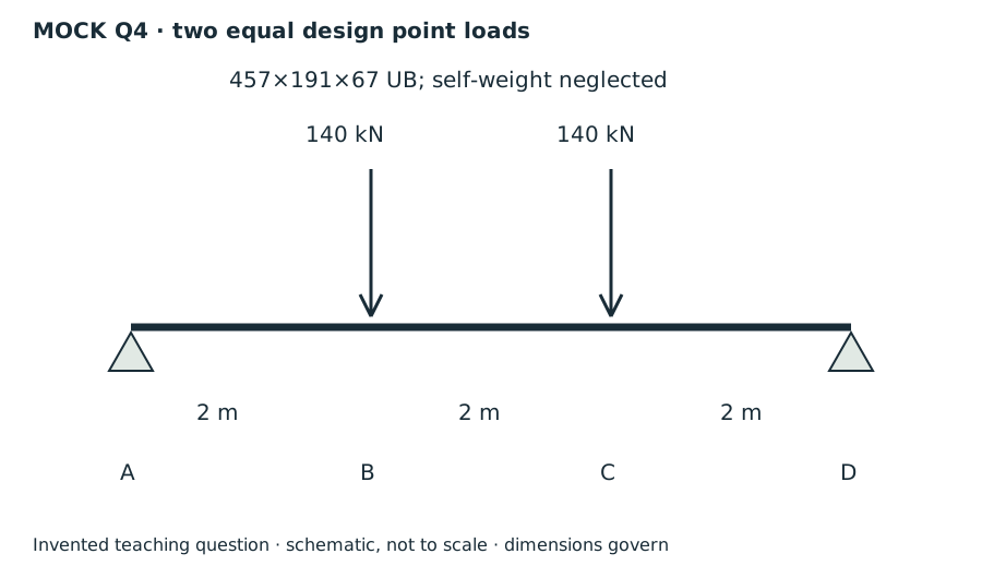
Invented mock-question diagram: two equal design point loads.
The UB has self-weight neglected; downward arrows at B and C each represent .
A–B, B–C and C–D are each .
A and D are vertical supports.
Schematic, not to scale; stated dimensions govern.Open full-size image.
Mechanism detailsA beam bends sideways and twists
The complete mechanism is explained below.
Read each stage together with its stated conditions; playback and interaction are not required.
- For the illustrated sagging beam the top flange is compressed.
- The unrestrained compression flange can move sideways while the complete cross-section twists.
Only effective restraints divide the member into unbraced segments.
They do not automatically add vertical supports.
Use the segment effective length, section properties and matching moment factor.
This is an exaggerated mode shape, not a calculated displacement.
After the timer ends
Make the next decision from the known conditions
Read the specific task below and identify the quantity or explanation it asks for.
Prediction, then explanation. Changing a load value may preserve the method. Changing the support or failure mechanism can require a different method.
Separate given, lookup, calculated and assumed values. State why the model applies. Keep necessary intermediate steps and units beside the equations.
A conditional answer states the exact condition required for its conclusion. It does not fill missing data with a guess.
Scope. A repeated result is not an independent verification. Use equilibrium, dimensions, a reverse substitution or an appropriate limiting case.
Check and takeaway. The explanation and answer are shown together in this edition. No response, score or completed interaction is needed to continue.
Apply the reasoning to this section’s data and conditions
Stop writing at minutes.
Then open the separate answers: Q1 · Q2 · Q3 · Q4.
Mark onlyQ1 plus your chosen two options for a -mark score.
The other option is useful untimed practice.
Mechanism detailsFollow the calculation sequence
The complete mechanism is explained below.
Read each stage together with its stated conditions; playback and interaction are not required.
- Locate the load, supports, connection geometry and any stated assumptions.
- Keep given values, table lookups and calculated values distinct; reconcile their units.
- The calculation player steps through the existing expressions in their original order.
Compare demand with resistance or the relevant limit.
Keep missing inputs and conditional conclusions explicit.