2023 BQ4: the same beam with two restraint arrangements
For a simply supported UB S355, assumed Class 1, carrying a central design point load and negligible self-weight: (a) find maximum shear/moment; (b) check LTB with support restraints only; (c) repeat with an additional effective midpoint lateral restraint.
Original source: Pastpaper/22ENGTY033.pdf — p. 6.
A given value comes from the question or diagram.
A lookup value comes from the named table.
A calculated value follows from the working.
Each assumption is stated where the calculation needs it.
Known information, diagram labels and unknowns
Vertical bending can trigger sideways motion
A beam has enough local bending resistance. Check whether its compression flange can move sideways and twist.
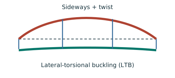
Prediction, then explanation. Adding a valid lateral restraint shortens a stability segment. It need not change the beam’s vertical reaction or moment diagram.
Identify the compressed flange and effective restraints. Calculate the specified slenderness, read buckling strength and compare resistance with the segment demand.
LE and ry use the same length unit. pb uses N/mm²; Sx uses mm³; Mb uses N·mm. mLT is dimensionless.
Scope. Use the specified section class, effective-length branch and loading condition. Load height alone does not prove a destabilizing case.
Check and takeaway. Removing a lateral restraint requires a new segment stability check. The old shorter-segment result cannot establish the longer segment’s adequacy.
Change the ruler, keep the quantity
A section table uses centimetres, but the strength calculation uses millimetres. The numbers must describe the same section.
Prediction, then explanation. Would every property increase by ten? No. The exponent determines how many factors of ten are needed.
First identify the physical quantity. Next convert each length factor. Keep force and length conversions separate when converting a moment.
Here n is the length exponent: 2 for area, 3 for section modulus and 4 for second moment of area.
Scope. Changing units changes neither the load nor the section. A conversion factor cannot repair a formula for the wrong physical quantity.
Check and takeaway. Illustration: . The fourth power belongs to the unit, not the number 2.
A table value has conditions
Find a design property without mixing a row, column or standard from a different case.
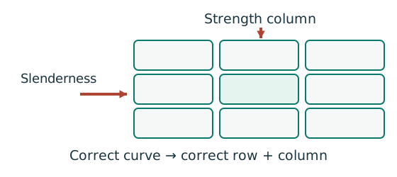
Prediction, then explanation. A different flange thickness can select a lower design strength even when the steel grade name remains unchanged.
Match the complete section designation. Read the relevant axis and unit. For strength tables, select material, thickness and curve before interpolating.
Given values come from the question. Lookup values come from a named table. Assumed values require an explicit condition.
Scope. A missing row or omitted restraint cannot be recovered from a schematic’s scale. Keep the result conditional when required data are absent.
Check and takeaway. Record the table, row, column and unit beside the substitution. That makes a later check possible.
Apply the reasoning to this section’s data and conditions
Lookup: Data File pp.9–10, exact UB row.
Dimensions on p.9; properties on p.10.
is overall depth.
is the clear web depth between root fillets, not the nominal designation.
| Property | Lookup value / conversion |
|---|---|
| Dimensions | D403.2, web t 6.8, flange T11.2, root r 10.2, clear d 360.4, all |
| Local ratios | ;。 |
| Major-axis properties | ; ; . |
| LTB properties | ; ; torsional index . |
Why this method applies
Moment shape matters within one segment
Represent a nonuniform moment distribution in the applicable member-buckling equation.
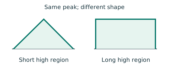
Prediction, then explanation. Two segments can have equal peak moment but different distributions. Their equivalent moment factors can therefore differ.
Evaluate moments from the true whole-beam analysis at the required positions. Apply the exact table’s weights, signs and lower bound.
mLT is an LTB factor. mx and my belong to the specified flexural checks. They are not interchangeable.
Scope. Some rules use magnitudes; others require signed ordinates. A factor does not reduce the actual moment used in a local section check.
Check and takeaway. Measure quarter points from the segment start, not automatically from the beam’s left support.
Use the same mechanism: Vertical bending can trigger sideways motion. Adding a valid lateral restraint shortens a stability segment. It need not change the beam’s vertical reaction or moment diagram.
A cut reveals the internal actions
Find where the beam moment is largest. A large load arrow alone does not locate that point.
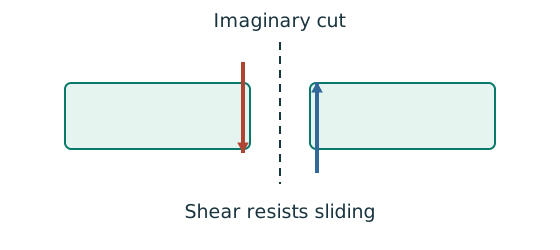
Prediction, then explanation. Under a uniform downward load, shear falls steadily. Moment reaches a stationary value where shear becomes zero.
Balance the forces on the cut piece to get V. Balance their moments about the cut to get M. Evaluate each load region separately.
x and L use m; w uses kN/m; V uses kN; M uses kN·m. These lines apply before any point load.
Scope. A point load adds a shear jump. A concentrated couple adds a moment jump. Check load points, supports and overhang roots too.
Check and takeaway. A UDL gives a sloping shear line and a curved moment line. A flat moment diagram therefore cannot represent a loaded UDL region.
Apply the reasoning to this section’s data and conditions
Vertical loading is identical in both cases.
Therefore, the reactions and BMD stay identical.
What changes is the unrestrained segment: one length becomes two lengths.
Both the segment moment factor and the segment buckling resistance must be recalculated.
(a) Maximum shear and moment —2 printed marks
Balance the isolated beam
Find the two vertical reactions before calculating internal shear or moment.
Prediction, then explanation. Move the same load toward B. Reaction B increases because the load has a larger moment arm about A.
Take moments about A. Reaction A has zero lever arm there. Then use vertical force balance to find reaction A.
P, RA and RB are forces in kN. L is support spacing and a is load position, both in m.
Scope. These expressions describe one point load on a simply supported beam. Add other loads through equilibrium; keep their actual positions.
Check and takeaway. Illustration: P = 60 kN, L = 6 m and a = 2 m give RB = 20 kN and RA = 40 kN.
Apply the reasoning to this section’s data and conditions
Physical interpretation: Why reactions balance the loads
Think of a seesaw that must neither fall nor turn.
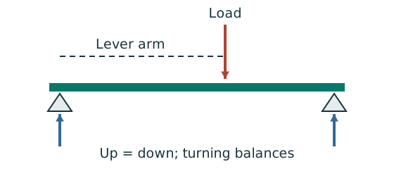
Sketch, not to scale; use the original dimensions.
- Upward and downward forces must balance.
- Take moments about a support to eliminate its reaction.
- Use perpendicular distance from the point to the force line.
Remember: A lateral restraint is not automatically a vertical support.
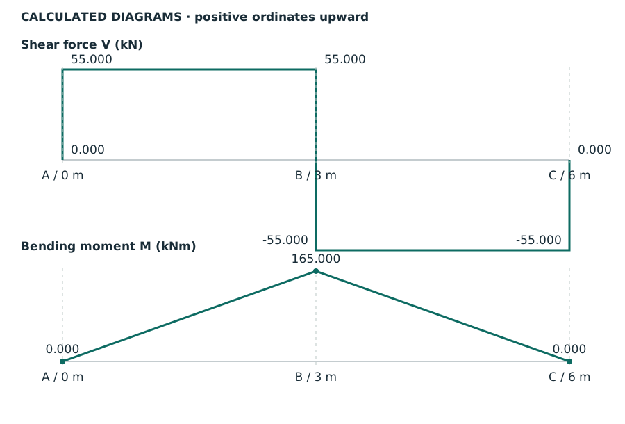
Teaching diagrams drawn from the calculation, not original source images.
Labels identify calculated diagrams, positive ordinates upwards, shear force and bending moment.
Positions are in , is measured in , is measured in ; A, B and C denote the left end, midspan and right end.
All values are also listed in the solution steps.Open full-size image.
Mechanism detailsBalance reactions and moments
The complete mechanism is explained below.
Read each stage together with its stated conditions; playback and interaction are not required.
This demonstrator is a simply supported 6 m beam with a 60 kN point load.
It is not the page’s original loading diagram.
.
Moving the load towards B increases .
.
The two upward reactions must sum to P.
With the load at midspan, .
End couples, UDLs and overhangs require their own equilibrium terms.
(b) End restraints only —14 printed marks
Use the same mechanism: Vertical bending can trigger sideways motion. Adding a valid lateral restraint shortens a stability segment. It need not change the beam’s vertical reaction or moment diagram.
Use the same mechanism: Moment shape matters within one segment. Two segments can have equal peak moment but different distributions. Their equivalent moment factors can therefore differ.
Move between two known values
The required slenderness lies between two table rows. Estimate the strength on the straight segment between those rows.
Prediction, then explanation. If the second strength is lower, moving toward that row must reduce the interpolated strength.
Subtract the lower input to find distance travelled. Divide by the input interval. Multiply that fraction by the output change.
x is the required input. The two known pairs are (x₀, y₀) and (x₁, y₁). f has no unit.
Scope. Use one table, curve and strength column. This interpolation does not permit extrapolation or inventing an intermediate steel section.
Check and takeaway. Illustration: between strengths 200 and 180, a fraction of 0.4 gives 192 N/mm². The result lies between both endpoints.
Apply the reasoning to this section’s data and conditions
Physical interpretation: A beam can escape sideways
The compressed flange can move sideways while the section twists.
Sketch, not to scale; use the original dimensions.
- Divide the beam at effective lateral restraints.
- Use each segment’s effective length to obtain its buckling resistance.
- Compare that resistance with the segment’s equivalent moment demand.
Remember: A section bending check alone does not check lateral-torsional buckling.
For the full segment the BMD is triangular with its peak in the middle.
At local quarter points ,,, the moments are ,,.
Normal-load effective length is the given segment length.
All quantities in and λᴸᵀ are dimensionless.
This Class 1 section has .
Table 8.3a, Data File p.5, pᵧ355 column:
The beam fails this LTB check.
Its section bending resistance exceeds .
However, that local-section fact cannot override the much smaller lateral-buckling resistance .
Mechanism detailsA beam bends sideways and twists
The complete mechanism is explained below.
Read each stage together with its stated conditions; playback and interaction are not required.
- For the illustrated sagging beam the top flange is compressed.
- The unrestrained compression flange can move sideways while the complete cross-section twists.
Only effective restraints divide the member into unbraced segments.
They do not automatically add vertical supports.
Use the segment effective length, section properties and matching moment factor.
This is an exaggerated mode shape, not a calculated displacement.
(c) Add an effective midpoint restraint —14 printed marks
Use the same mechanism: Vertical bending can trigger sideways motion. Adding a valid lateral restraint shortens a stability segment. It need not change the beam’s vertical reaction or moment diagram.
Use the same mechanism: Moment shape matters within one segment. Two segments can have equal peak moment but different distributions. Their equivalent moment factors can therefore differ.
Use the same mechanism: Move between two known values. If the second strength is lower, moving toward that row must reduce the interpolated strength.
Apply the reasoning to this section’s data and conditions
Physical interpretation: Which length belongs in the calculation?
A sideways tie can shorten the buckling region without shortening the beam’s vertical span.
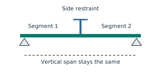
Sketch, not to scale; use the original dimensions.
- Separate vertical-support spacing from lateral-restraint spacing.
- Apply the course rule for the actual end restraint and loading.
- Keep the original vertical load analysis unless its supports change.
Remember: Restraints in one direction may not restrain the other direction.
The left segment now has moments atA and atB.
The right segment mirrors it.
The BMD over each segment is a straight triangle with its maximum at an end, not in the middle.
Normal-load effective length is the given segment length.
All quantities in and λᴸᵀ are dimensionless.
This Class 1 section has .
Table 8.3a, Data File p.5, pᵧ355 column:
Both halves pass.
A point load alone is not a lateral restraint; part(c) grants a separate effective restraint at that location.
Suggested method-credit evidence: show the changedLE, moment factor, //, table interpolation, resistance and conclusion.
Do not merely state “restraint makes it safe.”
Mechanism detailsA beam bends sideways and twists
The complete mechanism is explained below.
Read each stage together with its stated conditions; playback and interaction are not required.
- For the illustrated sagging beam the top flange is compressed.
- The unrestrained compression flange can move sideways while the complete cross-section twists.
Only effective restraints divide the member into unbraced segments.
They do not automatically add vertical supports.
Use the segment effective length, section properties and matching moment factor.
This is an exaggerated mode shape, not a calculated displacement.
Result and concise exam wording
Use the same mechanism: Balance the isolated beam. Move the same load toward B. Reaction B increases because the load has a larger moment arm about A.
Apply the reasoning to this section’s data and conditions
(a)V55 kN,M165 kNm. (b)LE6 m,mLT0.85,demand ;λ198.019802,v 0.812407,λLT140.120058,pb 79.879942,Mb 70.933388 kNm → fails. (c)TwoLE3 m segments,mLT0.6,demand ;λ99.009901,v 0.932256,λLT80.395537,pb 188.813390,Mb 167.666290 kNm → passes.
Normal-load/ assumptions as stated.
Misconceptions and checks
Use the same mechanism: Vertical bending can trigger sideways motion. Adding a valid lateral restraint shortens a stability segment. It need not change the beam’s vertical reaction or moment diagram.
Apply the reasoning to this section’s data and conditions
- Do not factor the design load.
- Do not usemLT0.85 for the half-span segment.
- Do not double the bolt/beam load merely because there are two segments.
- A local bending pass does not rule out LTB.
How the method transfers to a new variant
Use the same mechanism: Moment shape matters within one segment. Two segments can have equal peak moment but different distributions. Their equivalent moment factors can therefore differ.
Use the same mechanism: Vertical bending can trigger sideways motion. Adding a valid lateral restraint shortens a stability segment. It need not change the beam’s vertical reaction or moment diagram.
Use the same mechanism: A cut reveals the internal actions. Under a uniform downward load, shear falls steadily. Moment reaches a stationary value where shear becomes zero.
Apply the reasoning to this section’s data and conditions
- Keep the same vertical-load analysis.
- Redraw only the restraint boundaries for each case.
- Calculate a moment factor for each actual segment BMD.
- Recompute slenderness and resistance for that length.
- Compare equivalent demand withMb and state each case separately.
Prediction with explained answer
Use the same mechanism: Vertical bending can trigger sideways motion. Adding a valid lateral restraint shortens a stability segment. It need not change the beam’s vertical reaction or moment diagram.
Apply the reasoning to this section’s data and conditions
Prediction and explained answer.
Invented variant: with the midpoint restraint present, increase the central design load to .
Does LTB still pass?
Answer and reasoning
New maximum moment .
For each half-span, remains , giving demand .
Resistance remains , so LTB passes with only a small margin.
Other checks also need updating.
This conclusion covers only the stated LTB model.
Mechanism detailsA beam bends sideways and twists
The complete mechanism is explained below.
Read each stage together with its stated conditions; playback and interaction are not required.
- For the illustrated sagging beam the top flange is compressed.
- The unrestrained compression flange can move sideways while the complete cross-section twists.
Only effective restraints divide the member into unbraced segments.
They do not automatically add vertical supports.
Use the segment effective length, section properties and matching moment factor.
This is an exaggerated mode shape, not a calculated displacement.