3 October: welded connections and the start of steel-beam design
This lecture completes lap welds, brackets, angles and eccentric weld groups, then introduces steel-beam design and B1 floor loading. Two substantially overlapping recordings, A and B, are combined on this page. Each unit includes time links to both recordings.
Abbreviations: DL—Dead Load; LL—Live Load; ULS—Ultimate Limit State; SLS—Serviceability Limit State; UDL—Uniformly Distributed Load; LTB—Lateral-torsional Buckling; UB—Universal Beam; UC—Universal Column.
Key Points
- Fillet welds use effective throat and resistance per millimetre .
- Find total effective weld length, then convert to actual length using end rules. Select minimum leg size from the thicker plate.
- Allocate angle weld lengths by moment equilibrium about the centroid.
- For eccentric weld groups, measure eccentricity to the group centroid and combine direct and torsional shear using their included angle.
- For outward-rotating brackets, flange welds resist moment and web welds carry shear.
- For beams, assess lateral restraint, classify the section, then check shear and bending. Area load times tributary width gives line load .
Key Formulas
Exam Question Types
- Lap welds: determine lengths and check main- and cover-plate tension. → 850 kN lap weld: effective and provided lengths (Lap Weld)
- Eccentric weld group: determine the furthest-corner resultant and required leg size. → Eccentric weld Q6: from geometry to resultant (Eccentric Weld Group)
- Welded double angles: member resistance and weld lengths on both sides. → 350 kN double angles: total areas and side distribution (Double Angles)
- Bracket flange and web welds. → Q7: separate flange and web weld roles (Bracket Flange and Web Welds)
Design flows for these question types
- Breaks in both recordings have been omitted: approximately 01:30–01:40 in A and 01:25–01:40 in B.
850 kN lap weld: length, minimum size and plates (Lap Weld and Plate Checks)
What this unit is for: A short piece at each end of a weld does not count; this unit turns the calculated effective length into the length actually welded, then checks the plates themselves in tension.
Picture it this way: The two ends of a strip of sticky tape lift first, so those short pieces cannot be trusted. A weld is the same: beyond the calculated effective length, each run gets a little extra to make up for its ends. With the welds settled, the main plate and cover plates must still be checked against being pulled apart.
Prerequisites: Leg size, throat and effective length (Fillet Weld Geometry) · Material strength and member capacity (Stress and Resistance)
The previous lecture obtained approximately 202.4 mm effective length per weld. This lecture converts it to the actual length provided. Draw all four lines to distinguish total from individual length, then address the ends: for 6 mm legs, add 12 mm to each line and adopt 220 mm.
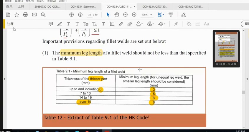
Minimum weld size is selected using the thicker connected plate. This differs from checking the thinner contact plate for bearing. Rather than memorising “always thin” or “always thick”, identify what the provision controls.
Force travels through plates before and after the welds, so the lecturer next checks main- and cover-plate tension. The 150×22 mm main plate uses ; each 130×12 mm cover uses . Different thicknesses give different design strengths.
Complete worked examples in this unit: 850 kN lap weld: effective and provided lengths (Lap Weld)
Lap welds: obtain length from resistance per millimetre
The example uses 6 mm fillet welds, and effective throat , giving resistance of 1.05 kN/mm.
850 kN requires approximately 809.5 mm total effective length . Four parallel weld lines share this, giving about 202.4 mm per line. Convert back to actual length using this problem's end-deduction rule.
- Each line needs about 202.4 mm. Add to obtain approximately 214.4 mm, then adopt 220 mm.
- Also check lap length, end returns and the tension resistance of the main and cover plates.
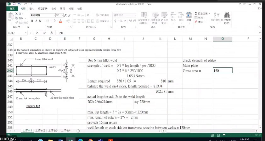
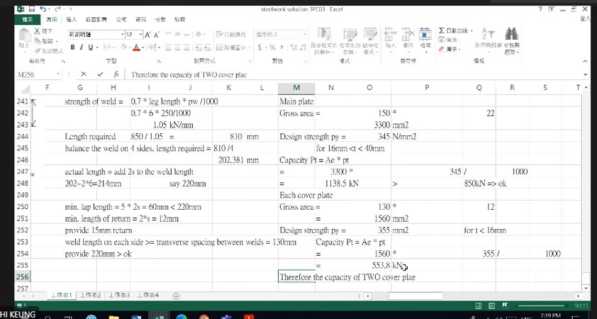
How to read this image: On the left, follow effective length to 220 mm. On the right, distinguish main-plate resistance 1138.5 kN from 553.8 kN per cover plate.
Look up minimum leg size using the thicker plate
The course table lists thickness bands and minimum leg sizes. Identify the thicker connected plate; do not select the minimum using the thinner plate.
The calculated weld size, specified minimum and practical welding details must all be satisfied. This segment focuses on the lookup procedure.
850 kN lap weld: effective and provided lengths (Lap Weld)
A main plate is lapped to two cover plates with four 6 mm fillet welds and must pass on an ultimate tension of 850 kN. Find the weld length each run needs, confirm that the 220 mm provided is enough, and check that the main plate and cover plates are not pulled apart.
Solution Route: Resistance per millimetre→total effective length →divide among four lines→end allowance→actual selected length→detailing checks.
Bracket welds: assign roles before calculating demand (Bracket Weld Model)
What this unit is for: The load on a bracket tries to tip it outwards and slide it down; this unit gives these two jobs to the flange welds and the web welds.
Picture it this way: A cupboard door hangs on two hinges. Its weight pulls the top hinge outwards and pushes the bottom hinge inwards, and this pull-and-push pair resists the tipping. The welds on the top and bottom flanges of a bracket form the same kind of pair, while the web welds hold up the downward force.
Prerequisites: Leg size, throat and effective length (Fillet Weld Geometry) · Why the position of a force matters (Moment and Eccentricity) · Turn the physical structure into a calculation model (Free-body Diagram)
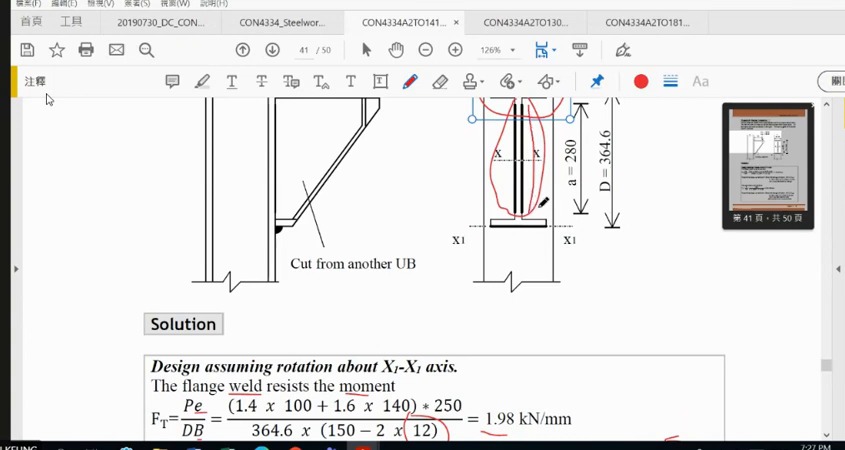
The lecturer models an outward-rotating bracket: flange welds resist moment and web welds carry shear. State this model first to identify which weld lengths receive each action.
The 364 kN comes from unfactored loads, 1.4×100+1.6×140. Convert 250 mm to 0.25 m to obtain 91 kNm. Upper and lower flange welds resist this through a force couple. Divide by effective weld length to obtain demand per millimetre.
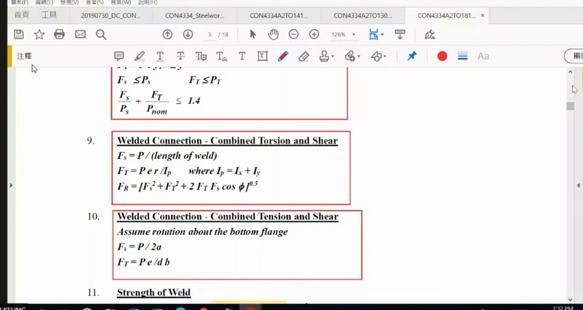
The formula sheet includes torsion plus shear and tension plus shear. Outward bracket rotation is the latter; the later Q6 group rotates in the weld plane and uses the former. Keep the models separate.
Bracket: factored loading produces both force and moment
The problem is not uniform shear alone. Eccentricity subjects the weld group to bending/tension and shear. Flange and web welds have different arrangements.
Calculate , then allocate actions to flange and web welds according to the stated model.
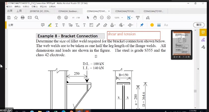
Different force-transfer roles in bracket welds
The model takes the bottom flange as the rotation reference: flange welds resist moment and web welds carry shear.
Measure lever arms and effective weld lengths according to this model. If the assumption changes, the same denominator cannot automatically remain.
Do not mix the two combined-action weld models
An in-plane eccentric weld group uses its centroid, polar second moment and corner distance for torsion. An outward-rotating bracket uses the course flange/web allocation.
Mark load direction and rotation mode before selecting an expression. Two problems both being eccentric does not make their methods identical.
Single and double angles: shared method, different factors (Single and Double Angles)
What this unit is for: One angle and a pair of angles follow the same method; this unit first checks that the angle itself can take the pull, then shares the weld length between the two sides.
Picture it this way: First check that the angle itself will not be pulled apart, then find the total weld length, then share it between the two sides by the position of the centroid. Label every line as per angle or for both angles together, so nothing is doubled or halved by mistake.
Prerequisites: How holes weaken a steel plate (Net and Effective Area) · Leg size, throat and effective length (Fillet Weld Geometry) · Why the position of a force matters (Moment and Eccentricity)
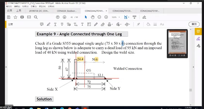
The lecturer first uses one 75×50×6 angle, then two 65×50×6 angles. Both need tension and weld-length checks, but outstanding-leg reduction, centroid data and angle count differ. List each problem's given data before applying the shared equilibrium method.
The single angle's weld length uses 197 kN. The double-angle 350 kN is already the pair's ultimate force. Double-angle areas include both angles, while total weld length must be divided between them. Label every line “per angle” or “total” to avoid factor errors.
Check the member's own resistance before designing weld force transfer. Member capacity and required weld length are consecutive checks along the load path, not interchangeable answers.
Complete worked examples in this unit: Single welded angle: check the member, then allocate welds (Welded Angle) · 350 kN double angles: total areas and side distribution (Double Angles)
Single welded angle: identify the connected leg and centroid
The long leg is welded. Dead and imposed loads of 95 and 40 kN give 197 kN after factoring. The angle centroid is not midway between the two welds.
Read the section geometry and centroid first, then allocate effective weld lengths. An arbitrary half-and-half split changes the resultant 's line of action.
Angle example: tension resistance and weld length
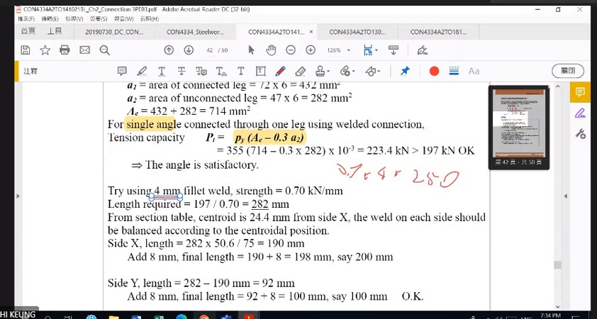
The screen gives , and . The course single-leg welded expression deducts 0.3a₂, giving 223.4 kN, above 197 kN.
Trying 4 mm welds gives 0.70 kN/mm and approximately 282 mm total effective length . Centroid distances divide this into about 190 and 92 mm.
- On side , add : 190+8=198 mm; adopt 200 mm.
- Side gives approximately 92+8=100 mm. Check detailing on both sides.
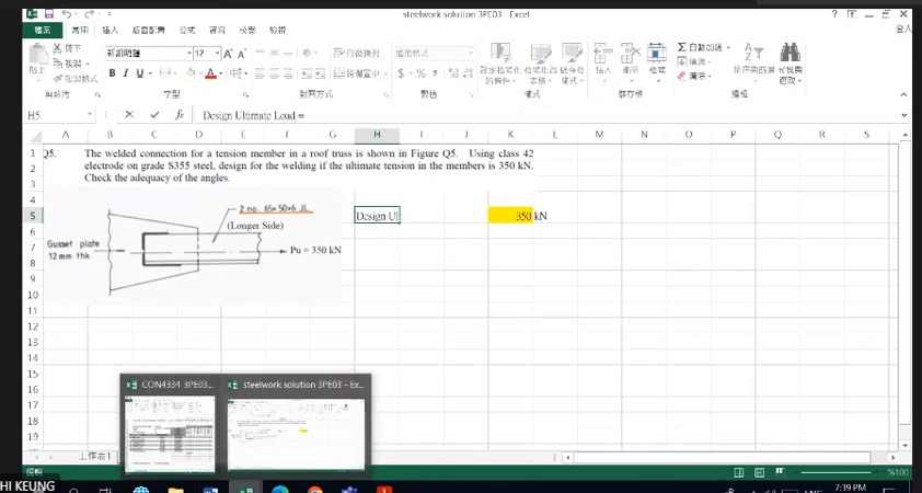
How to read this image: Read “2 no.” and “350 kN ultimate”. Identify each angle and the gusset plates on both sides.
Double-angle tutorial: keep areas and load sharing consistent
The worksheet specifies “2 no.” angles and sums both areas. State whether you are analysing one angle or the pair, to avoid doubling resistance while incorrectly halving load again.
Do not apply 1.4 or 1.6 again to a specified ultimate tension. Check the angles' tension resistance , then allocate weld lengths by centroid position.
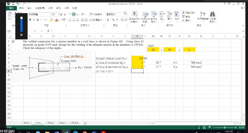
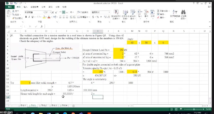
How to read this image: Confirm that 744 and 564 already total both angles, then apply the 0.15 reduction.
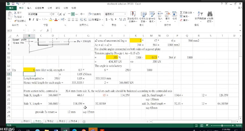
How to read this image: Follow total length 333.33 to 166.67 per angle, then actual lengths 130 and 65 mm. The intermediate label kN should read mm on dimensional grounds.
Single welded angle: check the member, then allocate welds (Welded Angle)
A 75×50×6 angle carries a tension from a dead load of 95 kN and an imposed load of 40 kN, and is fixed to a connecting plate with 4 mm fillet welds. Check that the angle itself is not pulled apart, then decide how long the weld on each side must be.
Solution Route: Design force→single-leg welded-angle resistance→total weld length→two-side equilibrium→actual lengths and selections.
350 kN double angles: total areas and side distribution (Double Angles)
Two 65×50×6 angles are welded by their long legs to either side of a 12 mm gusset plate and together carry an ultimate tension of 350 kN, using 6 mm fillet welds. Check that the angles are not pulled apart, then decide the weld length on each side of each angle.
Solution Route: Total-area resistance→total weld length→divide between angles→balance each angle's sides→actual lengths.
Q6: calculate the eccentric weld-group resultant (Eccentric Weld Group)
What this unit is for: The load is offset from the centre of the weld group within the plane of the welds; this unit finds the force per millimetre at the point farthest from the centre.
Picture it this way: The outer horses on a merry-go-round move fastest because they are farthest from the centre. When a weld group is twisted, the corner farthest from its centre likewise carries the most force per millimetre. The eccentricity is measured from the load to the centre of the weld group, not just to the column face.
Prerequisites: Leg size, throat and effective length (Fillet Weld Geometry) · Why the position of a force matters (Moment and Eccentricity)
The load is eccentric within the weld plane. DL350 and LL300 kN give 970 kN factored, shared by two groups at 485 kN each. Treat the four weld lines as one line group and locate its centre. The given 200 mm reaches only the column face; add half the 200 mm group width, or 100 mm, giving .
Direct shear is uniform over total weld length. Torsional shear increases with distance from the centroid. The lecturer checks the furthest corner and combines the components using their included angle. Both are in kN/mm, the force transmitted per millimetre of weld.
The line-group is in mm³ because throat thickness enters later in the resistance expression. Copying an mm⁴ solid-area formula would break dimensional consistency. A corner resultant of about 1.58 kN/mm gives a required leg of about 9.04 mm using the rounded displayed components.
Complete worked examples in this unit: Eccentric weld Q6: from geometry to resultant (Eccentric Weld Group)
Eccentric weld group: 200 mm is not the full eccentricity
Dead and imposed loads are 350 and 300 kN. Two symmetrical plates share them, giving design force (1.4×350+1.6×300)/2=485 kN per side.
Measure torsional eccentricity from the weld-group centre: .
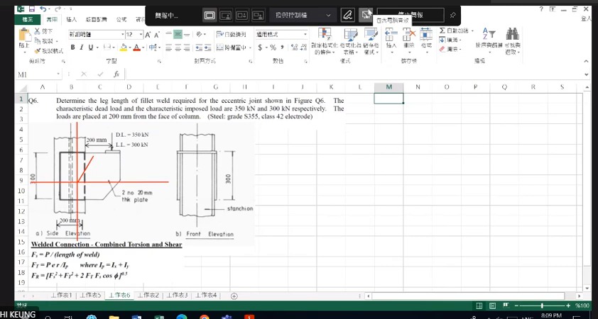
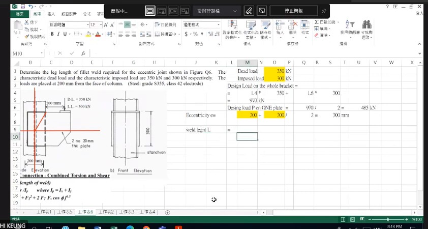
How to read this image: Locate the load line, group centre and 200 mm width. The expression adds the 100 mm half-width to eccentricity.
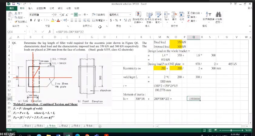
How to read this image: Sum the four lines to 1000 mm. Corner half-width 100 and half-height 150 determine .
Combine direct and torsional shear
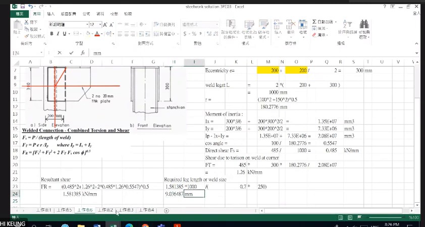
Total weld length is 1000 mm, so direct shear is 0.485 kN/mm. Torsional force per unit weld length is proportional to corner distance from the centroid.
The screen gives and . The components have different directions and must be combined accordingly.
Determine weld leg size from resultant force per unit length
The screen gives and . Combining them with their included angle gives approximately 1.58 kN/mm.
Use to find required leg size . With , the numerical requirement is approximately 9.04 mm; practical selection and detailing still remain.
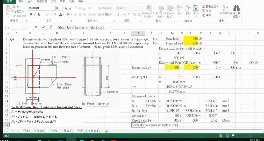
Eccentric weld Q6: from geometry to resultant (Eccentric Weld Group)
A load (dead 350 kN, imposed 300 kN) acts 200 mm from the column face and is shared equally by two 20 mm side plates. Each plate is welded all round, 200 mm wide and 300 mm high. Find the force per mm at the most heavily loaded point of the weld and the leg size needed.
Solution Route: Total design force→one-side force→centre/eccentricity →direct shear →torsional component→resultant →required leg size .
Q7: 600 kN bracket, from an 8 mm trial to 10 mm flange welds (Trial and Verification)
What this unit is for: A weld leg size has to be assumed before anything can be calculated; this unit starts from a trial size and, when it proves too small, increases it and checks again.
Picture it this way: Buying shoes, you put on one size first, and if it pinches you take the next size up and put that on too; the first size tried is not the answer. A larger weld leg also changes the length deducted at the ends, so the whole calculation is run again from the top.
Prerequisites: Leg size, throat and effective length (Fillet Weld Geometry) · Why the position of a force matters (Moment and Eccentricity)
This is a separate 600 kN bracket problem, distinct from the earlier 364 kN example. The question assigns moment to flange welds and shear to web welds; establish these two demand sets first.
The lecturer tries 8 mm flange welds, finds 9.54 mm required and then tries 10 mm. Changing leg size also changes the end deductions, so recalculate effective length instead of merely changing the size label.
For web welds, the worksheet deducts from the combined two-side length: 2×340−2×6=668 mm. Demand is 0.898 kN/mm and required leg 5.13 mm, so 6 mm is adequate. Deducting separately from each side gives 656 mm and 5.23 mm required; 6 mm remains adequate.
Complete worked examples in this unit: Q7: separate flange and web weld roles (Bracket Flange and Web Welds)
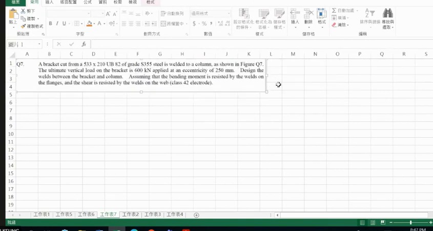
How to read this image: Confirm that this is Q7 and treat 600 kN as an already factored ultimate force.
Separate bracket Q7: a trial value is not a final answer
The question assigns moment to flange welds and shear to web welds. The worksheet first assumes a leg size , then checks effective length and resistance.
“Assume 8 mm” is a trial, not a satisfactory conclusion. Complete the capacity comparison, increase the size if needed, and verify again.
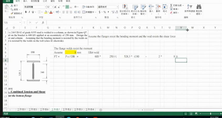
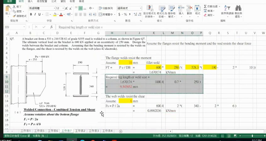
How to read this image: Read 1.670174 kN/mm and 9.543852 mm above, then check the brackets in the web-weld formula row.
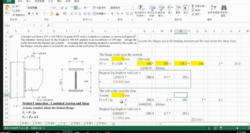
How to read this image: Read together with the preceding formula row. This value uses combined length , not .
Q7: separate flange and web weld roles (Bracket Flange and Web Welds)
A 533×210×82 UB bracket carries an ultimate force of 600 kN at an eccentricity . Flange welds of 10 mm and web welds of 6 mm are tried. Check separately that the flange welds can resist the moment and the web welds can resist the shear.
Solution Route: Accept the specified force allocation→deduct effective length for trial leg→force per millimetre→required leg→compare with trial.
Beam introduction: restraint, shear, classification and bending (Beam Design Route)
What this unit is for: A beam is checked item by item; this unit sets the order: whether the compression flange is held sideways, shear, section classification, and only then bending.
Picture it this way: A beam carries two kinds of internal force. Near a support it is like being cut by scissors, one side sliding past the other: that is shear. At mid-span it is like being bent by hand: that is moment. The web mainly deals with shear and the flanges mainly with moment, so the two are checked separately.
Prerequisites: Read an I-section and its section table (Section Properties) · Will the plate buckle before its material strength is fully mobilised? (Section Classification) · Why a beam moves sideways and twists (Lateral-torsional Buckling) · Internal shear force and bending moment in a beam (Shear Force and Bending Moment)
Moving from connections to a whole beam, the lecturer first asks whether its compression flange is laterally restrained. This determines whether LTB is needed. A thicker section does not replace restraint assessment.
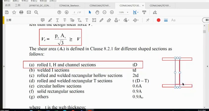
Separate actions and resistances: comes from loading analysis; comes from material strength and shear area . is not gross area: rolled I-, H- and channel sections use , with other definitions for other sections. checks shear; is the prerequisite for the low-shear bending expression.
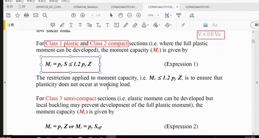
Classification describes whether compressed thin plates develop sufficient stress before local buckling. Classes 1/2 use the plastic expression, but still take the smaller of and 1.2pyZ. Read the course definitions of as plastic modulus and as elastic modulus first.
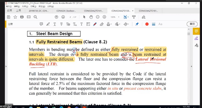
Moving to steel beams: identify lateral restraints first
Fully laterally restrained beams and beams restrained only at discrete points follow different design paths. The latter require LTB consideration.
The lecturer illustrates restraint of the compression flange by a slab. Full restraint must be supported by the actual construction and stated conditions; a slab's presence alone does not justify omitting stability assessment.
The complete steel-beam design checklist
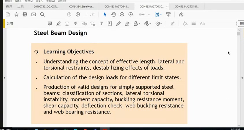
Start with effective length and lateral/torsional restraints, establish loading and internal actions, then check classification, bending, shear, deflection and web bearing /buckling.
These checks address different failure modes. Beam design is more than calculating a single .
Shear area depends on section type
This course uses for rolled I-, H- and channel sections. Welded I-sections, hollow sections and others have different displayed definitions.
Identify the section type before substituting. Gross area is not the effective shear area for every section.
Bending resistance under low shear
Low shear is the condition for using unreduced bending resistance here. Assess the shear coexisting at the same section.
Calculate both capacities and use the smaller. You cannot choose the larger merely because it looks more favourable.
B1 floor beam: build design load from tributary width (Floor Load to Beam)
What this unit is for: The weight of a floor slab must first become a load per metre on the beam; this unit goes step by step from slab thickness and tributary width to the design load on B1.
Picture it this way: A board laid across two parallel joists puts half its weight on each joist. A floor slab shares its weight between the beams on either side in the same way. Edge beam B1 has slab on one side only, so it receives just half of that one bay.
Prerequisites: How loads travel from the slab to the ground (Load Path) · Use units to identify what you are calculating (Units and Dimensions) · Turn the physical structure into a calculation model (Free-body Diagram) · Will the plate buckle before its material strength is fully mobilised? (Section Classification)
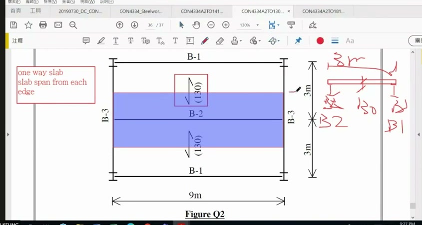
Read the slab's spanning direction in plan. B1 supports the slab edge along its 9 m length and takes half the adjacent 3 m slab bay, a tributary width of 1.5 m. That width differs from B1's own 9 m span .
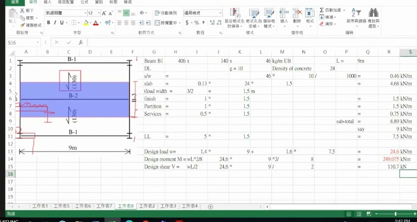
Convert slab thickness 130 mm to 0.13 m, multiply by unit weight 24 kN/m³ to obtain 3.12 kN/m², then multiply by 1.5 m tributary width to obtain 4.68 kN/m. Beam self-weight and other loads already in kN/m can be added directly; do not multiply every row by 1.5 again.
The lecture obtains 24.6 kN/m, 249.075 kNm and 110.7 kN, then classifies the section. Capacity and deflection follow on 17 October. The complete B1 example below connects both lectures into one calculation path.
Complete worked examples in this unit: B1 floor beam: from slab load to strength and deflection (Complete Beam Walkthrough)
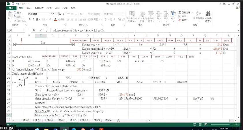
How to read this image: Use to determine , then examine and . Only afterwards use to calculate .
How one slab distributes load to three beam types
B1 is an edge beam with tributary width . Internal B2 receives slab load from both sides. Supporting beam B3 receives other beams' reactions .
Identify whether each load is in kN/m², kN/m or kN before setting up the calculation sheet.
B1 permanent and imposed line loads
The screen gives approximately 0.46 kN/m beam self-weight; slab load 0.13×24×1.5=4.68 kN/m; finishes 1.5, partitions 1.5 and services 0.75 kN/m. The total is 8.89, rounded to 9 kN/m in class.
Imposed load is 5×1.5=7.5 kN/m, giving design line load .
B1 internal actions and classification
For the 9 m simply supported UDL beam, and . Flange thickness 11.2 mm corresponds to here.
The screen gives and . Comparison with the relevant limits gives Class 1. Web shear area is 6.8×403.2=2741.76 mm².
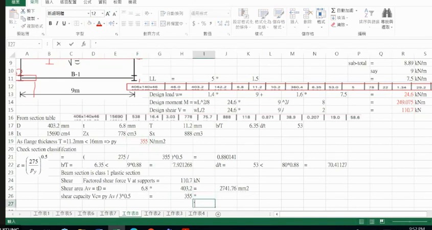
B1 floor beam: from slab load to strength and deflection (Complete Beam Walkthrough)
A 9 m simply supported edge beam carries a 130 mm slab with beams 3 m apart, plus finishes, partitions, services and a 5 kN/m² imposed load. Decide whether a 406×140×46 UB in S355 is strong enough and does not bend too far.
Solution Route: Slab thickness→area load →line load →ULS actions→classification→shear/bending resistance →SLS deflection . The example begins on 3 October and continues on 17 October; sources are listed separately.