Q7: separate flange and web weld roles (Bracket Flange and Web Welds)
Task: Trace the change from assumed 8 mm to 10 mm and check the two weld groups separately.
Go straight to Step 1 ↓Design flow for this type of question: Fillet-welded connection →
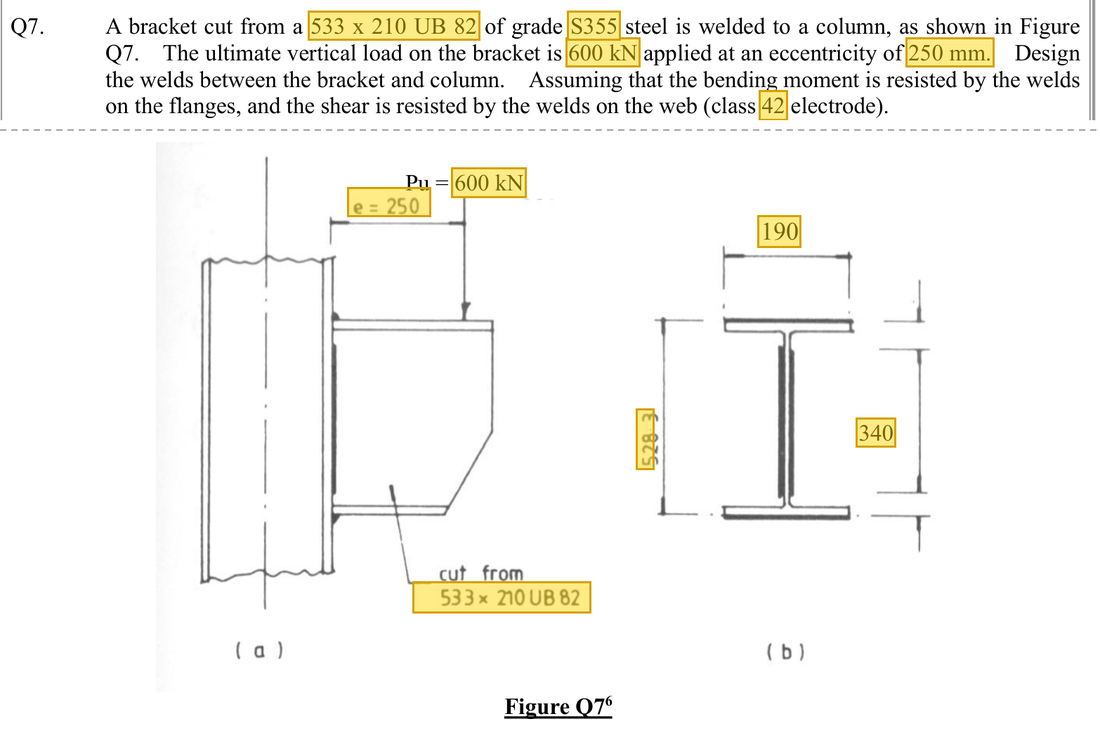
The question in short: A 533×210×82 UB bracket carries an ultimate force of 600 kN at an eccentricity . Flange welds of 10 mm and web welds of 6 mm are tried. Check separately that the flange welds can resist the moment and the web welds can resist the shear.
What differs from the previous example of this type: The previous example treated all the welds as one group sharing shear and twisting. Here the work is divided: flange welds take only the moment, web welds take only the shear, and a trial leg size is chosen first and then compared.
| Given | Value and Unit |
|---|---|
| Question data | 533×210×82 UB bracket, S355; ultimate load 600 kN; |
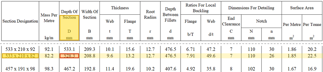
| Geometry | From the figure: section depth 528.3 mm (lever arm of the couple); usable flange length 190 mm; web 340 mm on each side |
| Welding | Class 42 electrode, ; try 10 mm on the flanges and 6 mm on the web |
Yellow: values given in the question. The same values are marked where they are substituted in the steps below.
Orange box: values read directly from the Data File, the same values boxed orange in the lookup screenshots. A value interpolated between two table rows is a calculation, so it has no box.
Solution Route: Accept the specified force allocation→deduct effective length for trial leg→force per millimetre→required leg→compare with trial.
This browser cannot show the 3D model.
The load passes from the bracket through the welds into the column flange. As the question assumes, the moment is resisted by a couple in the flange welds and the shear by the web welds.
- Ultimate load600 kN at 250 mm eccentricity
- Bracket: moment and shear;
- Flange welds resist the momentNeeds leg 9.544 mmUse 10 mm
- Web welds resist the shearNeeds leg 5.133 mmUse 6 mm
- Column flangeReceives the forces from the welds
- Step 1 · State the model first
Why this step: The force acts some distance away from the welded face, so besides shearing the bracket it also bends it. The moment is found first to show how much the flange welds must resist.
Flange welds resist moment 600×250; web welds carry 600 kN shear. Do not repeatedly distribute the same load uniformly across every weld.
Load path · What each group of welds doesThe moment is resisted by a pair of equal and opposite forces: the top flange weld in tension and the bottom flange weld in compression, a distance apart, so each force is . The 600 kN shear is carried entirely by the welds on the two sides of the web. - Step 2 · Flange effective length changes with trial size
Why this step: The ends of a weld are not counted as carrying load, and the amount deducted depends on the leg size. Whenever the leg size is changed, the effective length has to be recalculated.
For a 10 mm leg, the course deducts from the 190 mm length for the ends.
New symbols in this step- , : Leg size and effective throat; mm, with in this course
- , , : Flange weld length and effective length, web weld length on each side; mm
- Step 3 · Flange force per millimetre
Why this step: The moment acts like a pair of equal and opposite forces: one flange is pulled and the other pushed, a section depth apart. The flange weld has to carry this force.
Find force-couple tension from , then divide by effective weld length.
Where the numbers come from: from Step 2.
- Step 4 · Required flange leg
Why this step: This gives the smallest leg size whose throat can just carry the flange force. It is smaller than the trial leg size, so the trial flange weld is adequate.
Divide unit-length demand by 0.7pw, converting kN and N consistently.
New symbols in this step- , : Weld design strength N/mm²; resistance per millimetre kN/mm
Where the numbers come from: from Step 3.
Units: is in kN/mm; multiplying by 1000 gives N/mm. Dividing by in N/mm² gives the throat in mm, and dividing again by 0.7 gives the leg size in mm.
Data file lookup · Data Page 3 · Design strength of fillet weld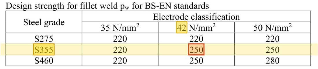
For S355 steel with class 42 electrodes the fillet weld design strength is .Yellow: given parameter, row or columnOrange: value read from the table, boxed orange in the text too - Step 5 · Total effective web length: record the worksheet faithfully
Why this step: The shear is carried by the welds on both sides of the web together, so the first thing needed is how much of their combined length counts as carrying load.
The worksheet uses K15/(2*O15−2*S15), deducting from the combined length of both sides. Its result matches the next screen. The calculation here first follows that expression.
- Step 6 · Web demand
Why this step: The whole shear is spread evenly over the effective length of the web welds. This gives the shear each millimetre of weld must carry, which is the demand on the web weld.
Combined length 668 mm gives the original 0.8982036 kN/mm. Do not silently change the denominator to 2(340−12).
New symbols in this step- , : Applied force; kN
- , , : Direct, torsional and resultant force per millimetre; kN/mm
Where the numbers come from: from Step 5.
- Step 7 · Web leg comparison
Why this step: The shear demand per millimetre is turned into a required leg size and compared with the trial value. The trial value is larger, so the throat of the web weld will not shear.
The original requirement is about 5.13259 mm, below the trial 6 mm.
Where the numbers come from: from Step 6.
Units: is in kN/mm; multiplying by 1000 gives N/mm. After dividing by 0.7 and by in N/mm², the unit left is mm.
- Step 8 · Alternative end deduction
Why this step: Each weld has two ends of its own, so deducting them separately gives a shorter effective length and a slightly larger demand. The check still passes with this more cautious figure, which makes the conclusion firmer.
Deducting from each side gives total effective length and required leg 5.227 mm, also below 6 mm. The lecturer does not explain the single deduction from combined length; both approaches give the same selection conclusion.
Units: The shear of 600 kN times 1000 gives N. Dividing by the effective length in mm, by 0.7 and by in N/mm² gives the leg size in mm.
Under the lecturer's model, 10 mm flange and 6 mm web welds satisfy the numerical comparison. “Assume 8 mm” is not a final answer merely because it appears in the sheet. Effective length changes with leg size and must be updated too. Check other detailing under the course conditions.
All the symbols of this example
| Symbols | Meaning and Units |
|---|---|
| , | Leg size and effective throat; mm, with in this course |
| , | Weld design strength N/mm²; resistance per millimetre kN/mm |
| , | Applied force; kN |
| , | Eccentricity and weld-group corner radius; mm |
| , , | Direct, torsional and resultant force per millimetre; kN/mm |
| , , | Flange weld length and effective length, web weld length on each side; mm |
Video positions: 3 October Recording B 01:45:00 · 3 October Recording B 01:50:00 · 3 October Recording B 01:55:00 · 3 October Recording B 01:57:00