Steel beam checks: floor beams, webs and lateral-torsional buckling
This recording continues the 3 October floor-beam problem. Beginners should first read the complete B1 example and the foundations on load paths, internal actions and section tables. This lecture turns the previous lecture's actions into strength, deformation and stability assessments. The values here follow the lecturer's corrected spreadsheet formulas.
Abbreviations: DL—Dead Load; LL—Live Load; ULS—Ultimate Limit State; SLS—Serviceability Limit State; UDL—Uniformly Distributed Load; LTB—Lateral-torsional Buckling; UB—Universal Beam; UC—Universal Column.
Key Points
- B1: obtain and from ULS line load , then check and . Use unfactored imposed load for SLS deflection .
- Under low shear, , Class 1/2 is the smaller of and 1.2pyZ.
- Check web bearing and buckling separately at point loads and support reactions ; the smaller resistance governs.
- B3 receives B2's reaction as a point load. Trace the load path.
- Unrestrained beams need an additional LTB check: , , , and , with adjusting demand.
Key Formulas
Exam Question Types
- Complete floor-beam check: loading, shear, moment and deflection. → B1 floor beam: from slab load to strength and deflection (Complete Beam Walkthrough)
- Web bearing and buckling at a support. → Local web checks: both modes must pass (Web Bearing and Buckling)
- Transfer of secondary-beam reactions to a primary beam. → B3: a support reaction loads the next beam (Reaction Transfer)
Design flows for these question types
- The 01:40–01:55 break has been omitted.
- The LTB trial calculations are completed in the next lecture, on 24 October.
B1: connect the previous lecture's loads to resistance checks (Beam Design Continuation)
What this unit is for: The shear and moment in B1 are already known; this unit compares each with the beam's capacity, then checks deflection using loads without load factors.
Picture it this way: The same beam follows two lines of work. One uses loads multiplied by load factors and asks whether the beam fails in shear or bending. The other uses everyday loads and asks how many millimetres it sags. Both lines share the span and the section, but never the loads.
Prerequisites: How loads travel from the slab to the ground (Load Path) · Internal shear force and bending moment in a beam (Shear Force and Bending Moment) · Read an I-section and its section table (Section Properties) · Excessive bending deformation versus insufficient resistance (Deflection)
The lecturer begins in the latter half of the worksheet, so this recording alone does not explain where 249.075 kNm comes from. The complete walkthrough below returns to the 3 October slab and B1 question, then proceeds to shear, bending and deflection in this lecture.
Identify units when reading capacities: is in kN, in kNm and deflection in mm. Compare each only with the corresponding demand. Shear resistance is checked before the low-shear condition because high shear can affect the bending resistance available.
By the end of this unit, separate one problem into two calculation paths: factored ULS loading leads to and ; the specified unfactored SLS loading leads to deflection . They share geometry and section data, but not every load value.
Complete worked examples in this unit: B1 floor beam: from slab load to strength and deflection (Complete Beam Walkthrough)
Distinguish the three basic checks first
In this course, denotes plastic section modulus and elastic section modulus. Confirm the notation before substituting tabulated values.
Under low shear, plastic-section bending resistance remains subject to the cap of 1.2 times elastic resistance. The course uses elastic modulus .
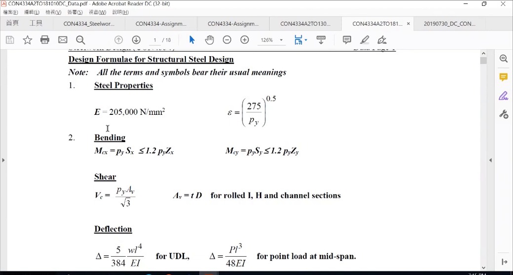
How to read this image: Identify the UDL and point-load diagrams before reading their deflection expressions. B1 and B3 later use different cases; do not copy one into the other.
B1: shear and cross-sectional bending
The displayed web shear area is 2,741.76 mm², giving , above the design shear of 110.7 kN.
The bending candidates are 315.24 and 331.428 kNm. Use the smaller, 315.24 kNm, which still exceeds .
- Classify the section first, then determine whether shear requires a reduction in bending resistance .
- Compare and in kNm. Do not compare a calculated Nmm value directly with kNm.
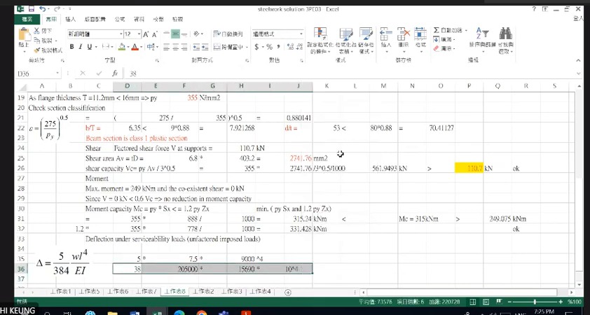
How to read this image: Read and , then both candidates and the 249.075 demand. Compare each resistance only with demand in the same units.
B1: deflection uses unfactored imposed load
This example uses unfactored imposed load , span and . In an N–mm calculation, 7.5 kN/m equals 7.5 N/mm.
Calculated deflection is approximately 19.92 mm, below 9000/360=25 mm. here relates to brittle finishes; it does not apply universally to every structure.
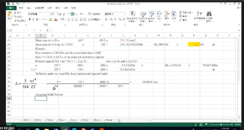
How to read this image: Locate unfactored 7.5, span 9000 and , then check 5wL⁴/(384EI). Both 19.92 and 25 are in mm.
B1 floor beam: from slab load to strength and deflection (Complete Beam Walkthrough)
A 9 m simply supported edge beam carries a 130 mm slab with beams 3 m apart, plus finishes, partitions, services and a 5 kN/m² imposed load. Decide whether a 406×140×46 UB in S355 is strong enough and does not bend too far.
Solution Route: Slab thickness→area load →line load →ULS actions→classification→shear/bending resistance →SLS deflection . The example begins on 3 October and continues on 17 October; sources are listed separately.
Local concentrated-force effects and initial section selection (Local Web Checks)
What this unit is for: A support reaction enters the beam through a short piece of web; this unit checks whether that piece is crushed or buckles, and picks a trial section from the moment.
Picture it this way: Stand a sheet of stiff card on edge and press down hard at one point on its top edge. The card may crumple right where you press, or the whole sheet may bulge sideways. A web under a concentrated force can fail in the same two ways, with very different capacities, so each is checked on its own.
Prerequisites: Why the position of a force matters (Moment and Eccentricity) · Read an I-section and its section table (Section Properties) · Material strength and member capacity (Stress and Resistance)
The web transmits overall beam shear, but a support reaction or point load must first enter through a local contact region. The lecturer therefore adds web bearing and buckling to the overall checks. These expressions require contact length and end geometry; the beam designation alone is insufficient.
For combined loading, calculate maximum moment from the correct model, then estimate the required section modulus. This screens candidate sections. Actual thickness may change , and classification or shear may change the resistance expression, so recheck the assumptions after selecting a section.
Local bearing and local buckling resistances can differ greatly. Comparing the same 292.3 kN reaction with both capacities below shows why the apparently generous 721.8 kN does not establish ample resistance to every local failure mode.
Complete worked examples in this unit: Initial section selection from load demand (Trial Section Selection) · Local web checks: both modes must pass (Web Bearing and Buckling)
Web bearing: how a concentrated force enters the beam
Support reactions or point loads enter the web through the flange. The local contact region and bearing length affect resistance.
The bracket is , with the entire bracket multiplied by and . It is not ().
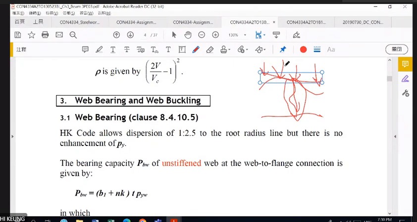
How to read this image: Identify bearing contact length and web geometry for the local bearing/buckling expressions. Overall beam does not replace all local data.
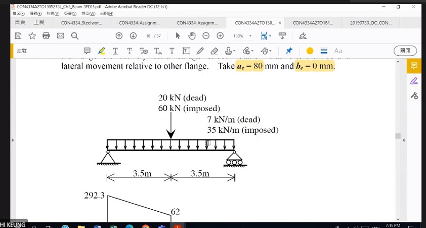
How to read this image: Read point loads DL20/LL60 and UDLs DL7/LL35. Factoring gives 124 kN and 65.8 kN/m for internal actions and initial selection.
Work backwards from design moment to a required section
The displayed factored point load is 124 kN and factored UDL is 65.8 kN/m over a simply supported 7 m span . Find internal-action demand before trying a section.
Assuming flange thickness no greater than 16 mm and gives a required plastic modulus of approximately 1,746 cm³. After initial selection, check actual thickness, classification, shear and deflection .
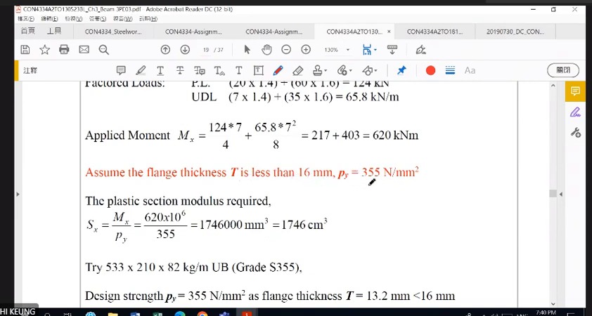
How to read this image: Identify the point load and UDL on the 7 m beam, calculate their moments separately and add them. Then estimate required from .
Compare web buckling and bearing separately
Compare the same concentrated reaction with both bearing and buckling resistances. Do not stop after only one passes.
The screen gives bearing resistance 721.8 kN but web-buckling resistance only about 297.5 kN. The latter is much closer to the 292.3 kN applied force and governs the margin.
- Locate the 160 mm bearing width and in the drawing.
- Select the correct expression branch from the relationship between and .
- Compare resistance with the concentrated force at that same location, retaining units and conditions.
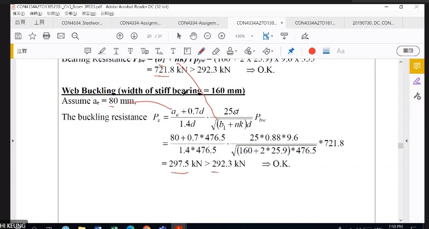
How to read this image: Compare reaction 292.3 separately with bearing resistance 721.8 and buckling resistance 297.5. The smaller latter value governs the margin between these two checks.
Initial section selection from load demand (Trial Section Selection)
A 7 m simply supported beam carries a midspan point load (20 kN dead, 60 kN imposed) and a uniform load over the whole span (7 kN/m dead, 35 kN/m imposed). In S355 steel, find a candidate section large enough for the moment.
Solution Route: Calculate moment→required modulus→table selection→recheck assumptions→complete remaining checks.
Local web checks: both modes must pass (Web Bearing and Buckling)
A 533×210×82 UB in S355 has a support reaction of 292.3 kN, which enters the 9.6 mm thick web through a bearing 160 mm wide. Decide whether the web is crushed or buckles sideways.
Solution Route: Identify the same force location→choose the end-distance branch→calculate both resistances→compare with the same demand.
B2: the internal beam and its corrected values (Interior Beam Results)
What this unit is for: Interior beam B2 has slab on both sides, so it carries more than an edge beam; this unit uses its own set of values to finish the shear, moment and deflection checks.
Picture it this way: Three people in a row carry two panes of glass. The one in the middle holds an edge of a pane in each hand, while the two outside hold one edge each. B2 is the person in the middle, loaded by the slab on both sides, so the edge beam's numbers cannot be copied.
Prerequisites: How loads travel from the slab to the ground (Load Path) · When to check strength and when to check deformation (Limit States)
Unlike B1, the internal beam collects slab load from both sides. Read the corrected , , capacities and deflection as one consistent dataset. Do not combine actions from before the correction with capacities from after it.
The bending candidates 522.205 and 552.096 are close and easily confused in speech. Record each expression together with its result, then take the smaller, rather than copying an approximate “five hundred something”.
The cross-sectional bending result here differs from the next lecture's unrestrained LTB result because they assess different failure modes. Complete the section and SLS checks below, then follow the later links to stability.
Complete worked examples in this unit: B2: the internal beam in the same floor (Interior Beam)
B2: use the complete corrected results
With the corrected loads, design shear is 218.88 kN and .
Take bending resistance as , above 492.48 kNm. Deflection under unfactored imposed load is approximately 21.28 mm, below 25 mm.
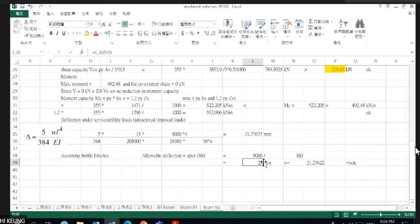
How to read this image: Confirm the screen is the corrected B2 worksheet. Record , , and deflection 21.276 as one consistent set.
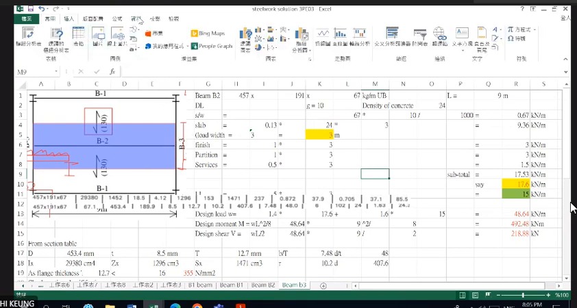
How to read this image: Check 17.53 rounded to 17.6, then 48.64, 492.48 and 218.88. The section row below supplies , , , and .
B2: the internal beam in the same floor (Interior Beam)
An interior beam in the same floor spans 9 m with a 3 m slab span on each side, a 130 mm slab and a 5 kN/m² imposed load. Decide whether a 457×191×67 UB in S355 passes for strength and deflection.
Solution Route: Trace loading from both slab sides; cross-check internal actions; classify and compare shear and two bending candidates; list SLS separately.
B3: transferred reactions and formula corrections (Transferred Reactions)
What this unit is for: One end of B2 rests on B3 at mid-span; this unit treats the reaction of B2 as a concentrated force on B3 and then runs the checks for B3.
Picture it this way: A person stands at the middle of a plank whose ends rest on two chairs, and each chair takes half the weight. B2 presses its end reaction onto B3 in the same way. For B3 that is a force at one point, not a load spread along its length.
Prerequisites: How loads travel from the slab to the ground (Load Path) · Turn the physical structure into a calculation model (Free-body Diagram) · Excessive bending deformation versus insufficient resistance (Deflection)
When the lecturer transfers B2's reaction to the B3 drawing, the physical quantity changes. The slab area load first produces a support reaction in B2; that reaction is now a point load on B3. Draw this load path clearly.
B3 carries both a central point load and self-weight UDL. Their strength effects can be calculated separately and added. The course deflection check uses the specified unfactored imposed point load. The 18.9 mm obtained while an old UDL expression remained on screen is not an alternative answer.
Geometrically, adds flange thickness and root radius. Understanding their positions helps prevent mistaking this addition for division.
Complete worked examples in this unit: B3: a support reaction loads the next beam (Reaction Transfer) · B3 support: local web bearing and buckling (B3 Local Web Checks)
B3: a B2 reaction becomes a point load
Do not copy B2's loading onto B3. B2 first carries slab load, then transfers its support reaction to B3. The displayed dead- and imposed-load reactions are 79.2 and 67.5 kN.
The factored point load is 218.88 kN, with an additional factored self-weight UDL of 1.072 kN/m. B3's analysis span is 6 m.
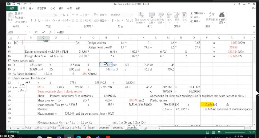
How to read this image: Locate the 79.2 and 67.5 kN reactions transferred from B2, then B3's self-weight in kN/m. Calculate the internal effects separately before adding them.
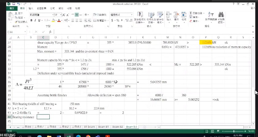
How to read this image: Confirm that 5.043 mm is point-load deflection, then read bearing width 150 mm and .
B3: point-load deflection and local bearing
The unfactored central imposed point load is 67.5 kN. After changing to the point-load formula, the displayed deflection is approximately 5.04 mm, below 6000/360=16.67 mm.
Web-bearing parameter is flange thickness plus root radius: 12.7+10.2=22.9 mm.
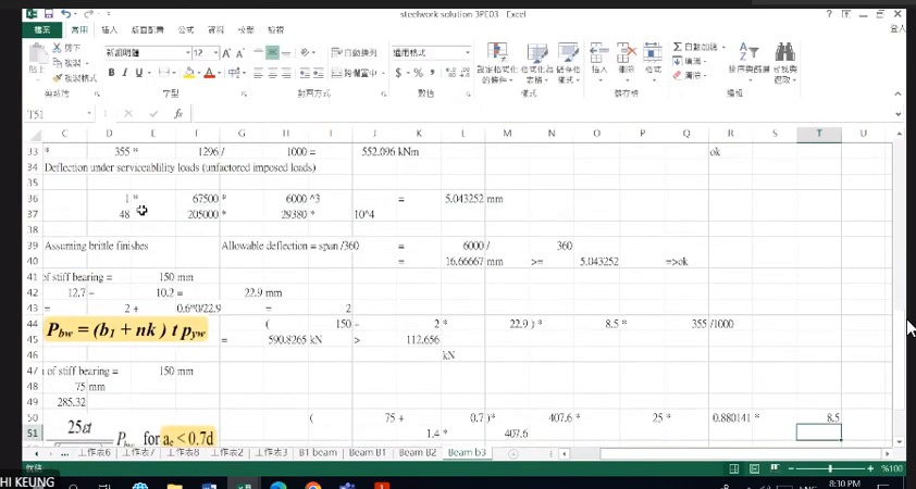
How to read this image: First note the switch to the central-point-load formula, then compare 5.043 with 16.67. The earlier 18.9 came from the intermediate UDL expression.
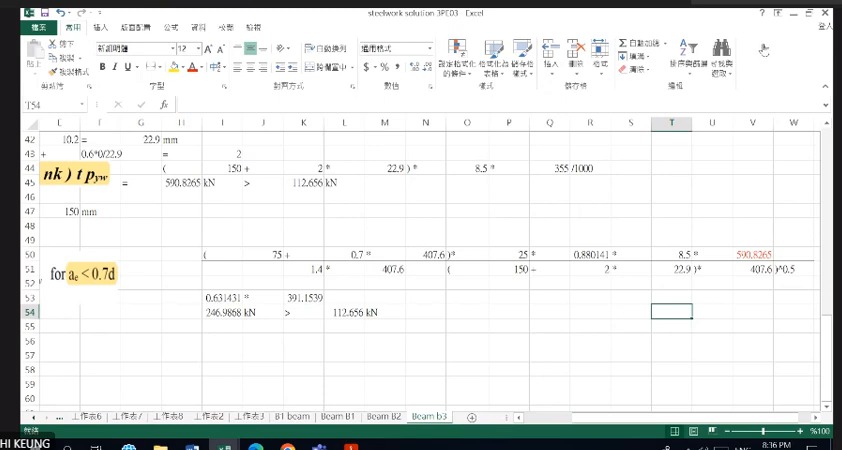
How to read this image: The right-hand side explicitly uses bearing resistance 590.8265. Finally, 0.631431×391.1539 gives 246.9868, above reaction 112.656.
B3: a support reaction loads the next beam (Reaction Transfer)
A 6 m simply supported beam (457×191×67 UB, S355) carries B2's reaction at midspan: 79.2 kN dead and 67.5 kN imposed, plus its own weight. Find the design moment and shear, and check the deflection.
Solution Route: Factored reaction →separate point-load and UDL effects→add→use the SLS central-point-load expression.
B3 support: local web bearing and buckling (B3 Local Web Checks)
At B3's support, a reaction of 112.656 kN enters the 8.5 mm thick web through a bearing 150 mm wide. Decide whether the web above the support is crushed, or buckles sideways like a thin plate.
Solution Route: →bearing resistance→ branch→local buckling→compare reaction .
Unrestrained beams: from section strength to stability (Lateral-torsional Buckling)
What this unit is for: A beam with a strong enough section can still move sideways and twist when its compression flange is not held; this unit sets out the procedure for that check.
Picture it this way: Rest a thin steel ruler on edge across two supports and press down at the middle. Long before it fails by bending downwards, its top edge slips sideways and the whole ruler twists. Hold the top edge with a finger part-way along and it becomes far steadier.
Prerequisites: Why a beam moves sideways and twists (Lateral-torsional Buckling) · Read an I-section and its section table (Section Properties) · Instability can precede material crushing (Buckling)
The lecturer discusses lateral restraints before consulting effective-length and moment-factor tables. Draw the start, end and load positions of the unrestrained segment first. Understanding how that segment can deform gives a traceable basis for and .
Ordinary slenderness uses only length and radius of gyration . The course method then introduces section stability parameters to obtain before reading . Do not put the first worksheet value above two hundred directly into the table.
Trial calculations continue at the end of this recording; the B2 and B3 results follow on 24 October. Establish two paths here: geometry and section properties lead to resistance ; loading and moment shape lead to equivalent demand .
The lecturer also uses a separate 5 m beam with three point loads to explain moment diagrams. The 82 kN reaction and 121.3 kNm midspan moment at 02:30:00 belong to that problem. On returning to B2, use 9 m, and its corresponding section.
Lateral restraint changes effective length
LTB involves lateral movement of the compression flange together with section twist. Passing cross-sectional bending does not guarantee member stability.
Identify lateral/torsional restraints, end conditions and whether the load has a destabilising effect before choosing . Total span alone is insufficient.
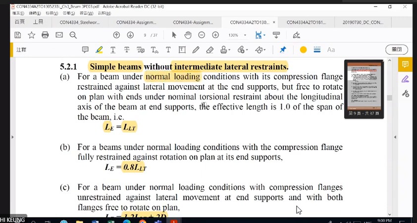
How to read this image: Identify the compression flange and its lateral supports before considering restraint requirements. The presence of a slab alone does not establish every restraint condition.
Equivalent moment factor and the moment diagram
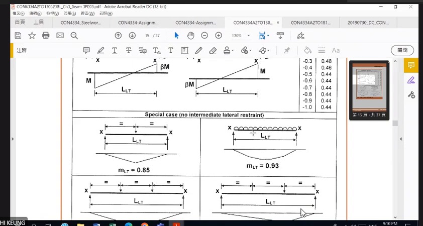
represents non-uniform moment distribution. Draw the correct bending moment diagram before selecting the matching table case.
Compare with . adjusts demand, whereas is the strength used for buckling resistance. Their roles differ.
How to read this image: Match the actual end and intermediate restraints to the relevant effective-length row. Do not mix ideal and actual conditions from different rows.
Distinguish strength, modulus and resistance in the tables
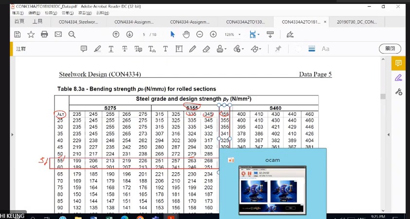
Read , and stability parameters from the section table, first making length units consistent. Obtain equivalent slenderness by the course method, then read .
For interpolation, keep the steel-grade/strength column fixed and use the adjacent slenderness rows. Crossing into a wrong column can produce a plausible but incorrect resistance.
How to read this image: Match the moment diagram to the tabulated loading case before reading . It multiplies demand, not resistance.
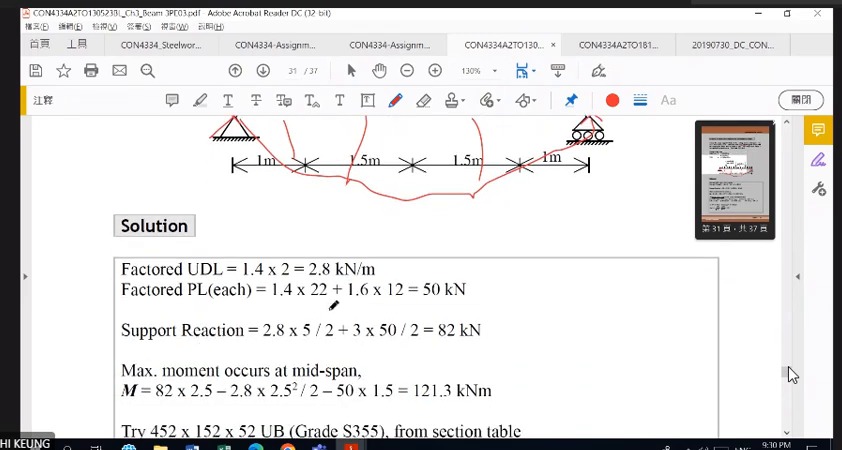
How to read this image: This problem has and three loads each, giving reactions of 82 kN. The expression 82×2.5−2.8×2.5²/2−50×1.5 gives about 121.3 kNm. Keep it separate from B2.
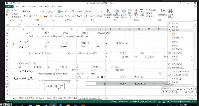
How to read this image: The upper part uses 15 N/mm and to reproduce 21.276 mm. The lower part begins LTB with and . Passing deflection does not establish stability.
B2 LTB trial calculation and continuation in the next lecture
The screen uses and , giving . This is ordinary slenderness , not the final .
The lecturer begins entering stability parameters near the end of this recording. B2 and B3 LTB conclusions are completed on 24 October. This section first establishes the full calculation sequence.
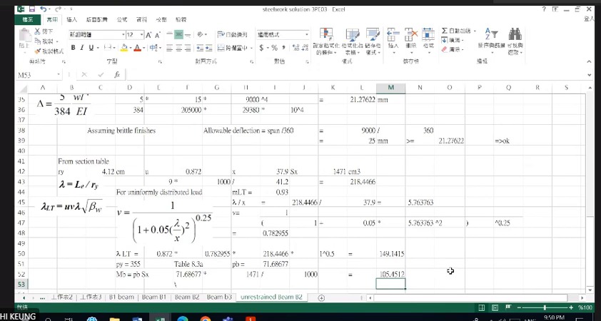
How to read this image: Follow , , , and cell by cell, then read . The final decision comes in the next lecture.