B3: a support reaction loads the next beam (Reaction Transfer)
Task: Connect the load path with two loading models and understand the lecturer's deflection -formula correction.
Go straight to Step 1 ↓Design flow for this type of question: Laterally restrained beam →
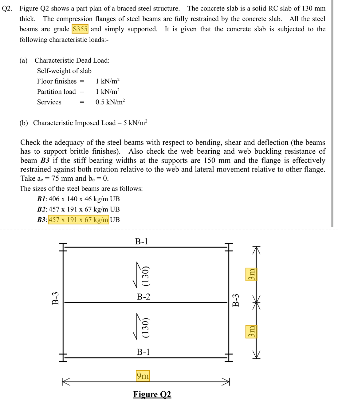
The question in short: A 6 m simply supported beam (457×191×67 UB, S355) carries B2's reaction at midspan: 79.2 kN dead and 67.5 kN imposed, plus its own weight. Find the design moment and shear, and check the deflection.
What differs from the previous example of this type: B2's load is spread evenly along its length. B3's main load is one point load at midspan from another beam, so the moment and deflection formulas change.
| Given | Value and Unit |
|---|---|
| Span and model | 457×191×67 UB, S355; 6 m simply supported; midspan point load and self-weight UDL |
| Reaction source | Support reactions of B2: dead 79.2 kN; imposed 67.5 kN |
| ULS self-weight line load | 1.072 kN/m |
| SLS data | ; ; central imposed load 67.5 kN |
Yellow: values given in the question. The same values are marked where they are substituted in the steps below.
Orange box: values read directly from the Data File, the same values boxed orange in the lookup screenshots. A value interpolated between two table rows is a calculation, so it has no box.
Solution Route: Factored reaction →separate point-load and UDL effects→add→use the SLS central-point-load expression.
The reaction of B2 becomes a point load at the midspan of B3. B3 takes it, with its own weight, to the columns at its ends.
- Reaction of B2Dead 79.2 and imposed 67.5 kN →
- Moment in B3 (midspan)
- Shear in B3 (supports)
- Deflection (imposed load)Demand 5.043 mmCapacity 16.667 mmUtilisation 0.30
- Support reactions112.656 kN at each end, through the web into the column (next example)
- Step 1 · Treat reactions as forces
Why this step: B2 rests on B3, so the force holding B2 up presses down on B3 with the same size. Dead and imposed parts stay separate because their load factors differ.
79.2 and 67.5 are the end reactions of B2 (kN, not kN/m), found from the B2 line loads times the 9 m span divided by 2; they become the midspan point load on B3.
New symbols in this step- , : Unfactored dead and imposed loads; kN/m or kN
- Step 2 · Point-load moment
Why this step: The point load sits at midspan, as far as possible from both supports, which is where it bends the beam most.
A central point load gives at each support and midspan moment ()()=.
New symbols in this step- , , : Area load kN/m², line load kN/m, point load kN
Where the numbers come from: from Step 1.
- Step 3 · Self-weight moment
Why this step: The beam's own weight is spread along its length and also bends it. The effect is much smaller than the point load's, but it is still counted.
Use separately for UDL. Do not add unlike loads before putting them into one formula.
- Step 4 · Combine internal actions
Why this step: Both loads act at the same time, so the beam must resist their combined moment and shear. These totals are the demands for the later checks.
In this linear-elastic simply supported model, add both loads' effects at the same location.
New symbols in this step- , : Moment demand in kNm; shear demand in kN
Where the numbers come from: from Step 2; from Step 3; from Step 1.
Load path · Load, shear force and bending momentThe point load makes the shear diagram jump at midspan and the moment diagram a triangle with its peak under the load. The self-weight is a UDL and only curves the diagrams slightly. - Step 5 · Return to unfactored imposed load for SLS
Why this step: Deflection is about how far the beam sags in everyday use, so only the imposed point load without load factors is used, with the point-load deflection formula.
This course check uses , and .
New symbols in this step- , : Deflection mm; demand/resistance utilisation is dimensionless
Units: 67.5 kN times 1000 gives 67500 N and 6 m gives 6000 mm. in cm⁴ times 10^4 gives mm⁴, because 1 cm is 10 mm, multiplied four times.
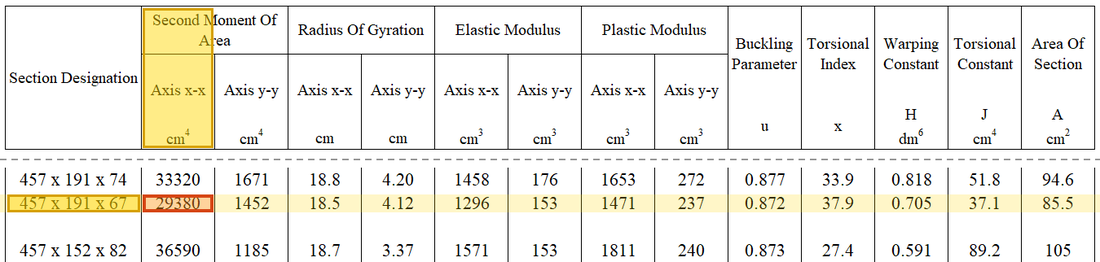
Data file lookup · Data Page 1 · Steel properties
Data Page 1, steel properties: modulus of elasticity (printed as 205,000).Yellow: given parameter, row or columnOrange: value read from the table, boxed orange in the text too - Step 6 · Compare with the limit
Why this step: The deflection formula must match the shape of the load. Using the uniform-load formula for a point load gives a wrong sag and could even make the beam seem to fail.
6000/360=16.667 mm. The approximately 18.9 mm obtained temporarily with a UDL formula is not the answer for this point-load model.
New symbols in this step- , , : Span in m or mm; end reactions in kN
Units: The 6 m span times 1000 gives 6000 mm (1 m is 1000 mm), so the limit can be compared with the deflection in mm.
Data file lookup · Data Page 2 · Table 5.1 Deflection limits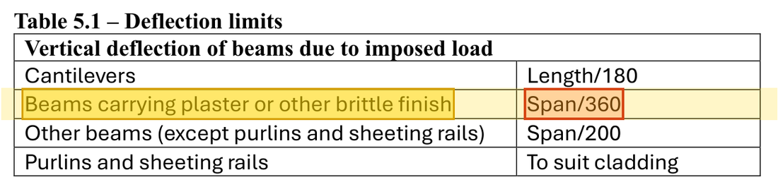
For beams carrying plaster or other brittle finish, the imposed-load deflection limit is span/360.Yellow: given parameter, row or columnOrange: value read from the table, boxed orange in the text too - Step 7 · Check local support effects separately
Why this step: A large force enters a short length of web. The thin web may be crushed there or bulge sideways, even when the beam as a whole is strong enough.
A concentrated force entering the web requires bearing length and other data for local bearing/buckling checks. Overall shear resistance cannot replace them.
B3 point-load moment greatly exceeds its self-weight moment. This explains the next lecture's observation that self-weight has a small effect in a particular LTB diagram interpretation. Whether it may be neglected still follows the lecturer's stated assumption at that step.
All the symbols of this example
| Symbols | Meaning and Units |
|---|---|
| , , | Area load kN/m², line load kN/m, point load kN |
| , , | Span in m or mm; end reactions in kN |
| , | Moment demand in kNm; shear demand in kN |
| , , , | Overall depth, classification web depth, web thickness and flange thickness; mm |
| , , , | Shear area mm², second moment of area mm⁴, plastic/elastic moduli mm³ |
| , , | Design yield/bending buckling strength and elastic modulus; N/mm² |
| , | Deflection mm; demand/resistance utilisation is dimensionless |
| , | Unfactored dead and imposed loads; kN/m or kN |
Video positions: 17 October 01:19:00 · 17 October 01:30:00