Eccentric bolted connections and fillet-weld design
This lecture extends ordinary bolts to eccentric actions, then introduces welding. First identify load direction, line of action and connection centre on the drawing. The later expressions answer which bolt or weld segment carries the greatest demand. Full intermediate steps are provided for Q3, Q4 and the welded-angle problem.
Abbreviations: DL—Dead Load; LL—Live Load; ULS—Ultimate Limit State; SLS—Serviceability Limit State; UDL—Uniformly Distributed Load; LTB—Lateral-torsional Buckling; UB—Universal Beam; UC—Universal Column.
Key Points
- An eccentric load equals a force through the centre plus moment . First distinguish in-plane rotation from outward rotation.
- In-plane eccentric bolt groups: direct shear and torsional shear are combined at the furthest bolt using their included angle.
- For outward bracket rotation, bolt tension increases with distance from the rotation line. Check combined shear and tension; the course limit here is 1.4.
- Fillet-weld resistance per millimetre is . Required length is force divided by resistance per millimetre.
- Allocate weld lengths on an unequal angle by centroid distances, not equally.
Key Formulas
Exam Question Types
- In-plane eccentric bolt group (Q3). → Q3: combine shear at each bolt in an eccentric in-plane group (In-plane Eccentric Bolts)
- Bracket bolts under shear plus tension (Q4). → Q4: bracket-bolt shear, tension and interaction (Shear–Tension Interaction)
- Weld-length allocation for an unequal angle. → 65×50×8 angle: centroid and unequal weld lengths (Unequal Weld Lengths)
Design flows for these question types
- Opening arrangements and the 01:25–01:35 break have been omitted.
- The lecturer changes the Q3 load in the worksheet; this page uses the corrected values.
From the formula sheet back to connection geometry (Connection Geometry)
What this unit is for: Hole positions are measured in several ways; this unit tells apart centre-to-centre spacing, end distance and the clear distance from a hole edge, and introduces failure where a block of plate is torn out.
Picture it this way: Pull hard on a sheet in a ring binder and the small piece of paper between the hole and the edge comes away whole. How far the hole is from the edge and from the next hole decides how easily that happens. Measuring from the hole centre and from the hole edge gives two different lengths.
Prerequisites: Use units to identify what you are calculating (Units and Dimensions) · Several failure paths in a bolted connection (Bolted Connections) · How holes weaken a steel plate (Net and Effective Area)
The lecturer first reviews formulas and spacing tables. Beginners should draw a hole and label bolt diameter , hole diameter , pitch, clear hole spacing and the plate end, then add a load-direction arrow. These five lengths differ; , and in the bearing expressions each need an identifiable location.
Keep material strengths distinct: plates use or , bolt shear uses , and bearing uses or . Although all are in N/mm², they have different physical meanings. Equal units establish dimensional compatibility, not interchangeability.
The lecturer next discusses failure paths near holes. Net-section tension crosses the hole row; block shear runs along the bolt group's sides and then tears across it. Sketch the potential detached block to see why bolt resistance alone cannot establish plate safety.
A formula sheet is a tool: establish applicability first
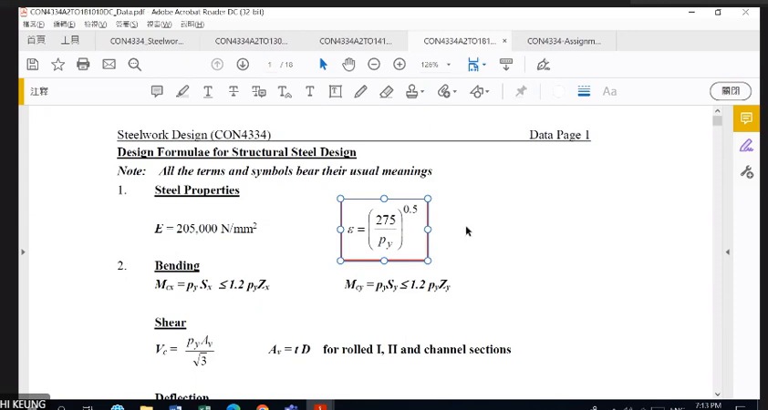
The lecture first reviews shared material parameters. Later connection problems likewise require the correct steel grade, design strength and units.
is elastic modulus and is steel design strength. Bolt strengths , and , and weld strength , are separate properties and cannot replace one another.
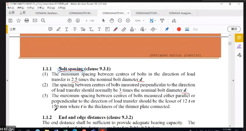
Bolt spacing has minimum and maximum limits
The screen gives minimum centre spacing of along the force direction and generally transversely. Maximum centre spacing is the smaller of and 150 mm.
is the thinner connected plate thickness. Pitch is centre-to-centre distance; distinguish it from end distance , edge distance and clear spacing in bearing expressions.
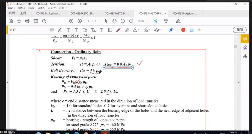
How to read this image: Read each symbol's definition before measuring it in the question drawing. Confirm that the fourth expression uses bolt strength .
Hole deductions and block shear
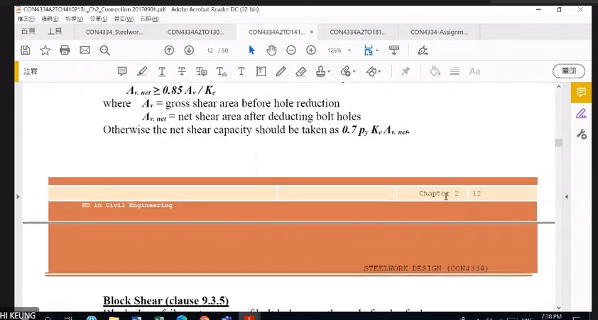
Holes may be ignored in shear area only under specified conditions. Otherwise, use the resistance expression based on net shear area.
Block shear detaches a block of material along combined shear and tension paths around a bolt group. Checking bolt shear alone is insufficient.
- Mark possible shear paths along the loading direction on the connection drawing.
- Then mark the tension path perpendicular to the load and the holes it intersects.
- Determine areas from that path and the course expression. Bolt count does not replace a plate-failure check.
Two eccentricity models: identify the rotation first (Two Eccentricity Models)
What this unit is for: A load that misses the centre of a bolt group twists the joint; this unit tells apart turning within the plane of the plate and tipping outwards.
Picture it this way: A wall clock swinging round its nail turns within the wall surface; bolts resist that kind of turning by shear alone. A loaded wall shelf wants to tip outwards and pulls its top screws out of the wall; there the bolts carry tension as well as shear.
Prerequisites: Why the position of a force matters (Moment and Eccentricity) · Turn the physical structure into a calculation model (Free-body Diagram) · Several failure paths in a bolted connection (Bolted Connections)
An offset force can be represented by a force through the connection centre plus a moment . How the connection resists that moment depends on its three-dimensional orientation. In-plane rotation mainly adds bolt shear; outward rotation puts some bolts into tension.
In-plane torsional shear increases with distance from the group centre and acts tangentially around it. For outward rotation, the lecturer assumes a rotation reference line and varies tension with distance from that line. Draw both sets of arrows before substituting into formulas.
The demonstration with 348 kN and differs from the later Q3 with 100 kN and . The lecturer demonstrates the method before assigning Q3; keep their data separate.
Two eccentric connections, two analysis models
An in-plane eccentric load gives a bolt group direct shear and torsional shear . The torsional component has a different direction at each bolt.
When a bracket rotates outwards, bolts carry direct shear and tension. Identify the rotation mode before selecting a force-distribution model.
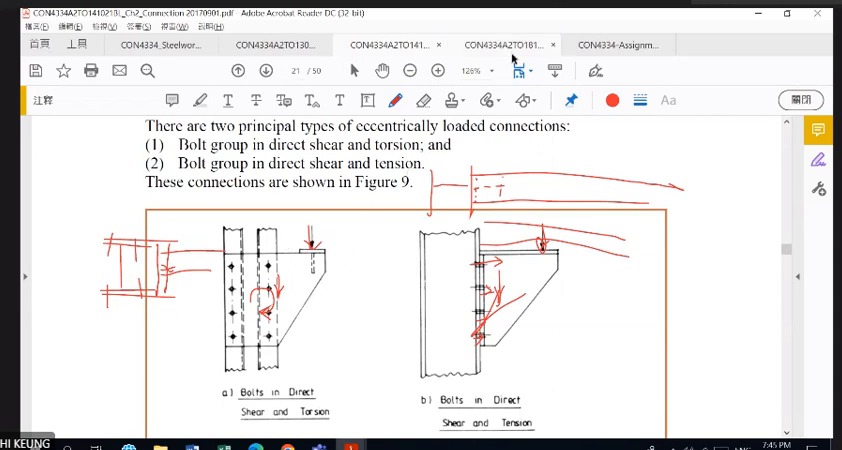
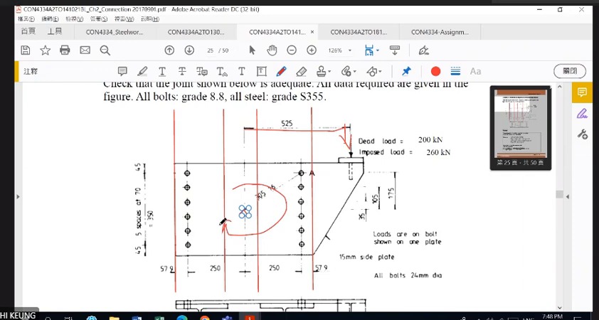
How to read this image: Locate the horizontal distance from the load line to the group centre, then determine the force carried by each side plate.
Combined shear and tension checks
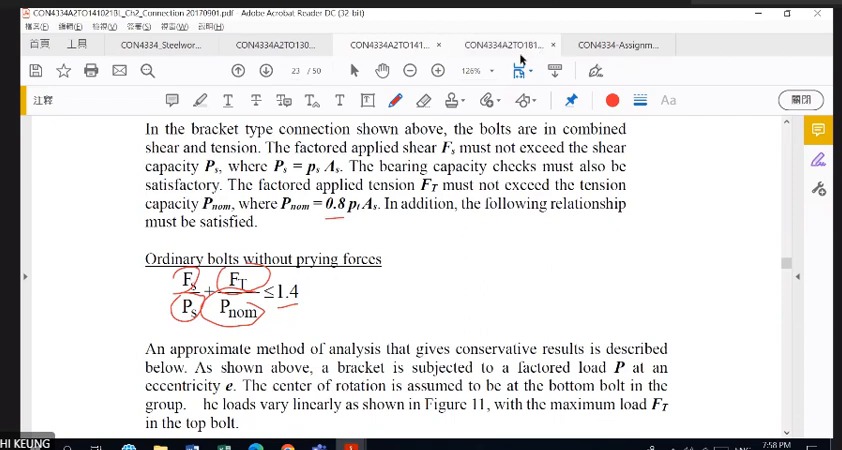
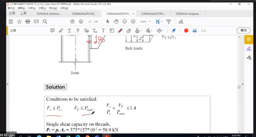
First satisfy shear and tension resistance separately, then check interaction. The screen uses ; distinguish it from other tension-resistance definitions.
The approximate bracket analysis assumes a rotation centre. Tension varies with distance from that centre, so the furthest tension bolt is generally most critical.
Bolt-group torsion example: determine group geometry
The total factored load is divided equally between two sides: per side.
Eccentricity is 0.525 m, so . The sum of squared bolt distances represents the group's geometry and determines torsional shear at each bolt.
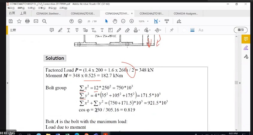
How to read this image: Measure row distances from the rotation reference line. A row with zero lever arm is not the maximum-tension row.
Different roles for bracket flange and web bolts
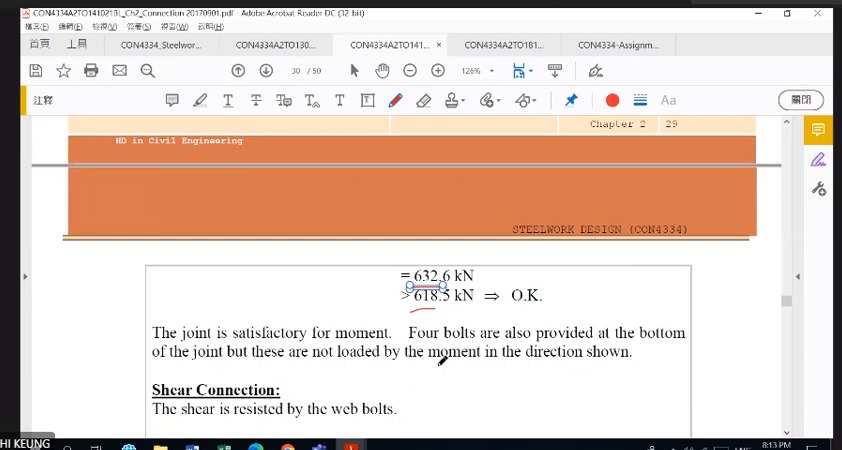
The screen notes that some bottom bolts are present but do not carry the specified moment demand for the illustrated bending direction. Do not treat every bolt as equally tensioned.
Where the model assigns shear to web bolts, check that group's shear and bearing. Do not arbitrarily add capacities from groups serving different force-transfer roles.
Q3: recalculate the resultant after correcting the load share (Correcting the Load Share)
What this unit is for: An eccentric load gives every bolt its equal share of shear plus an extra shear from twisting; this unit finds the bolt that carries the most.
Picture it this way: First settle the load on one side plate only and share it equally among the bolts. Then find the extra force that twisting puts on each bolt, largest for the bolt farthest from the centre. The two forces point in different directions, so combine them by direction and look at the corner bolt that works hardest.
Prerequisites: Why the position of a force matters (Moment and Eccentricity) · Several failure paths in a bolted connection (Bolted Connections)
The lecturer initially uses 200 kN and obtains larger shear components, then changes to 100 kN for one side. The formulas stay the same, but halving the load halves the results. The analysed object changes, not the steel resistance.
The sum of squared distances describes group geometry. Moving bolts further from the centre changes torsional resistance distribution, but plate and spacing requirements still apply. This expression alone does not justify arbitrary enlargement of the layout.
The worked example first sums individual bolt coordinates, then combines forces at the critical corner. Only square roots and basic algebra are needed; the angle is linked to the directions of the two forces in the drawing.
Complete worked examples in this unit: Q3: combine shear at each bolt in an eccentric in-plane group (In-plane Eccentric Bolts)
Tutorial Q3: distinguish the whole bracket from one side plate
The whole bracket carries an ultimate load of 200 kN. With symmetrical sharing between the side plates, each side carries 100 kN.
Calculate direct shear , torsional shear and the resultant at the critical bolt, then determine the required bolt resistance or size.
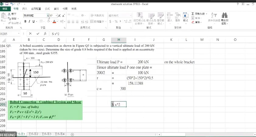
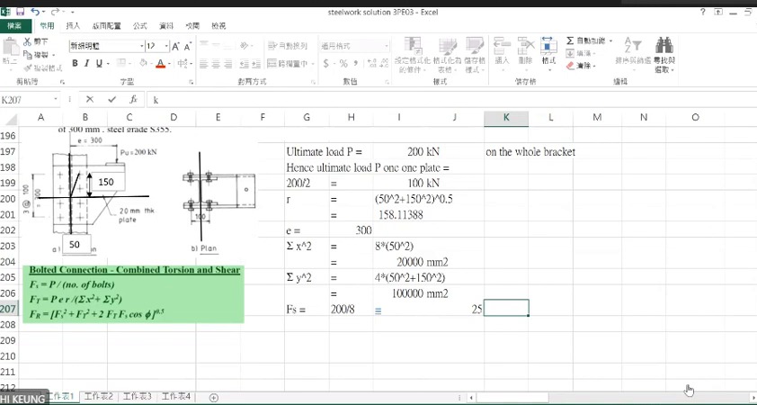
How to read this image: Read and distances, include every bolt in the squared-distance sum, then calculate corner radius .
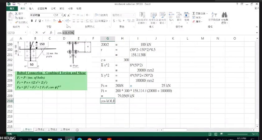
How to read this image: Note and . This image traces the error; it is not the final answer.
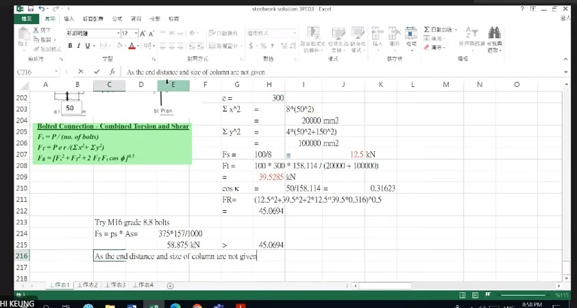
How to read this image: Confirm the load has been divided by 2, then check , and resultant 45.07, finally comparing with 58.875.
Q3: combine shear at each bolt in an eccentric in-plane group (In-plane Eccentric Bolts)
A bracket carries an ultimate load of 200 kN, shared by two matching side plates. Each side has 8 bolts, and the load acts 300 mm from the centre of the bolt group. Find the bolt with the largest force and decide whether M16 bolts are adequate.
Solution Route: Allocate between sides→centroid/squared-distance sum→direct shear →torsional shear →vector combination→bolt selection.
Q4: check interaction after the individual components (Interaction Check)
What this unit is for: A bolt that is sheared and pulled at once has both actions using up its strength together; this unit checks the worst bolt with a combined formula.
Picture it this way: The bracket tips outwards like a book cover being opened: the farther from the spine, the higher it lifts. The bolt row farthest from the turning line at the bottom is pulled hardest, while shear is shared equally. Each action is then written as a fraction of its capacity, and the two fractions are added and compared with the limit.
Prerequisites: Why the position of a force matters (Moment and Eccentricity) · Several failure paths in a bolted connection (Bolted Connections) · Combined axial force and bending (Interaction Checks)
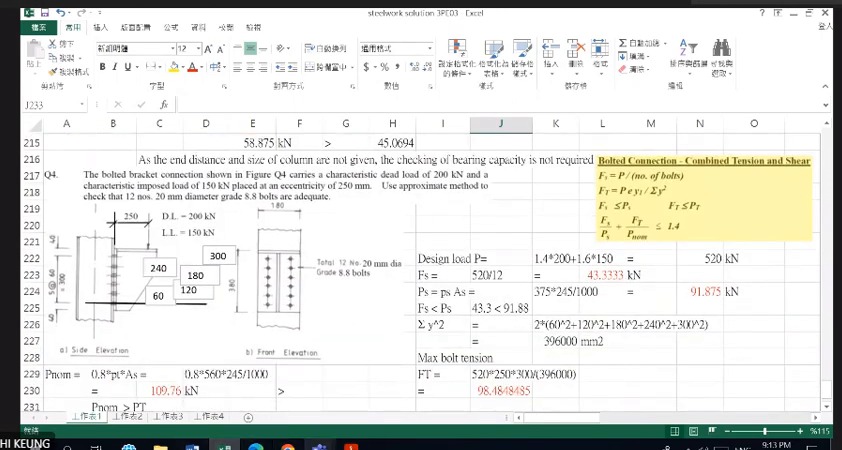
Q4 loading rotates the bracket outwards. Under the stated assumption, direct shear is shared by 12 bolts, but tension is not uniform: rows further from the bottom rotation line carry more tension. Dividing total force by bolt count solves only the shear part.
The lecturer's interaction expression adds each demand divided by its own resistance. The resulting dimensionless ratios can be added. Do not add 43.33 kN directly to 98.48 kN and compare the sum with one type of resistance.
This example gives an interaction value of about 1.37, compared with this expression's limit of 1.4. Later column expressions have a limit of 1. Keep these limits separate, and always write the complete inequality and right-hand limit.
Complete worked examples in this unit: Q4: bracket-bolt shear, tension and interaction (Shear–Tension Interaction)
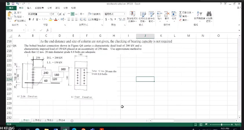
How to read this image: Measure row distances 0, 60 and onwards to 300 mm from the bottom row, then identify the furthest tension row.
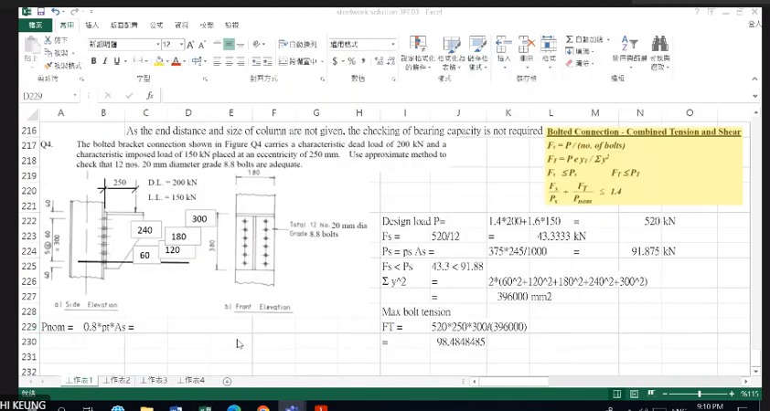
How to read this image: Follow the worksheet from shear per bolt to the sum of squared row distances. Do not sum all distances first and then square.
Tutorial Q4: checking a bracket with twelve M20 bolts
Given DL=200 and LL=150 kN, . Direct shear over 12 bolts is 43.33 kN per bolt. Grade 8.8 and give .
The screen also gives critical bolt tension of approximately 98.48 kN and . After the individual components pass, calculate the interaction expression.
Q4: bracket-bolt shear, tension and interaction (Shear–Tension Interaction)
A bracket is fixed by 12 M20 bolts in two rows of 6. It carries a dead load of 200 kN and an imposed load of 150 kN with an eccentricity of 250 mm. Decide whether the bolts are adequate when sheared and pulled at the same time.
Solution Route: Design force→direct shear →moment/squared-distance sum→top-bolt tension→individual capacities→interaction.
Start welding with throat and load-carrying area (Fillet Weld Basics)
What this unit is for: A fillet weld has a triangular cross-section and the force must cross its narrowest part; this unit uses the throat to find how much force each millimetre of weld can pass.
Picture it this way: Picture a fillet weld as a triangular bead of sealant pressed into a corner. The force has to cross the narrowest part of the triangle, the throat, which is shorter than the leg you can see. Every extra millimetre of length adds the same strength, so find the strength per millimetre first, then the length needed.
Prerequisites: Leg size, throat and effective length (Fillet Weld Geometry) · Material strength and member capacity (Stress and Resistance)
A fillet weld looks triangular, but its resistance uses effective throat. Locate leg and throat in the foundation diagram. Recognise as a different geometric dimension, then see how times area produces force.
A 1 mm-long weld segment has effective area . Its capacity is therefore force per millimetre. Dividing total force by this capacity gives length. This dimensional reasoning helps detect a missing N-to-kN conversion.
The lecturer separately checks minimum leg size , effective length and end returns. The load-derived size is only one lower bound; the minimum weld size set by the thicker plate and the problem's detailing rules must also be satisfied.
Fillet welds: effective throat is not leg size
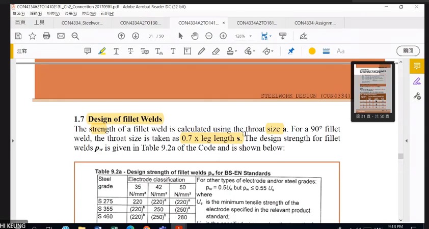
Fillet-weld resistance uses effective throat , not leg size directly. Electrode classification and parent-steel grade jointly determine .
For example, the common S355/Class 42 combination in this course uses . Find resistance per millimetre of weld before calculating length.
Minimum leg size and detailing require separate checks
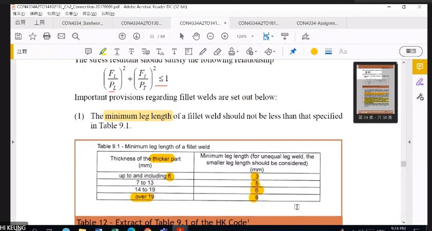
The course table uses the thicker connected plate to set minimum weld size, preventing an excessively small weld being chosen from resistance calculations alone.
Effective length, actual length, end-return length and lap length are different. Complete these detailing checks after finding the required load-carrying length.
Centroid-based distribution, followed by lap welds (Centroid and Weld Length)
What this unit is for: The pull in an angle does not act midway between its two welds; this unit shares the weld length unequally between the two sides to match where the pull acts.
Picture it this way: Two people carry a bucket on a pole: whoever the bucket hangs closer to carries more. The pull in the angle acts closer to one weld, so that weld must be longer. The two welds together make up the total length needed; each side does not need the total.
Prerequisites: Leg size, throat and effective length (Fillet Weld Geometry) · Why the position of a force matters (Moment and Eccentricity)
An unequal angle's centroid is not midway between its longitudinal welds. The lecturer balances moments to allocate weld length so the resultant follows the required line of action. Adequate total length does not justify an arbitrary equal split.
The centroid data for this lecture's 65×50×8 angle differ from the next lecture's 65×50×6 double angles. Record section dimensions, quantity and centroid distances for each problem rather than reusing a ratio because both contain 65 mm.
The final 850 kN lap problem has four weld lines and an already ultimate load. The next lecture converts effective to actual length and checks the plates. Complete the current screen first, then continue to 3 October.
Complete worked examples in this unit: 65×50×8 angle: centroid and unequal weld lengths (Unequal Weld Lengths)
Distribute welds on both sides of an angle by centroid position
Given DL=60 and LL=70 kN, the factored force is 196 kN. With 6 mm welds, and total effective length is approximately 186.7 mm.
The angle centroid is at unequal distances from the two weld lines. Their resultant must pass through the required line of action. Allocate lengths using moment equilibrium about the centroid.
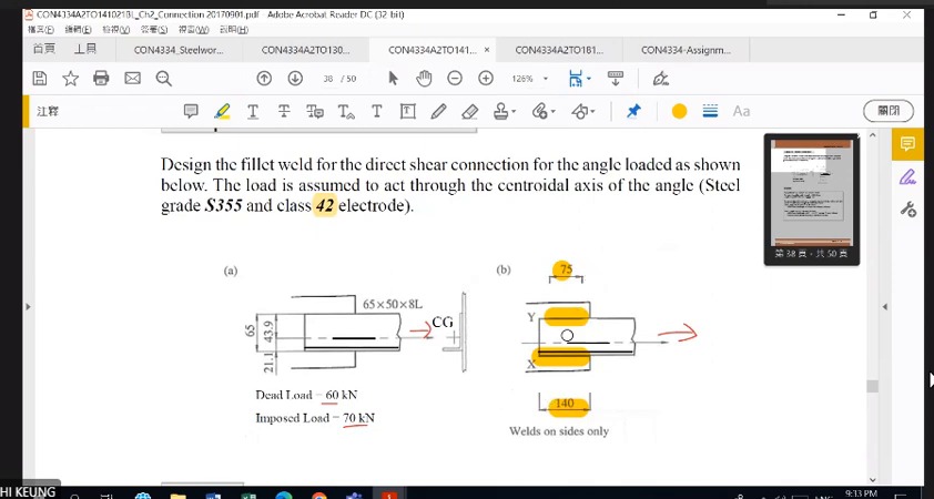
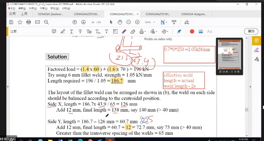
How to read this image: Read centroid distances 21.1/43.9, then effective lengths 126/60.7. Add 12 and choose actual lengths 140/75 mm.
850 kN lap weld: prepare the next lecture's worksheet
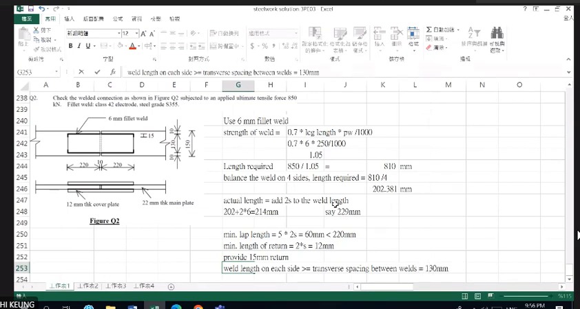
The 850 kN is already an ultimate force; do not factor it again. The four welds require about 810 mm total effective length , or 202.4 mm each.
This lecture sets up weld calculations. The next continues with actual lengths, end returns and main/cover-plate strength.
65×50×8 angle: centroid and unequal weld lengths (Unequal Weld Lengths)
A 65×50×8 angle carries a tension from a dead load of 60 kN and an imposed load of 70 kN, and is fixed with 6 mm fillet welds. Its centroid is 21.1 mm and 43.9 mm from the two edges. Decide the weld length on each side.
Solution Route: →resistance per millimetre→total effective length →side allocation→end allowance→actual lengths.