Q4: bracket-bolt shear, tension and interaction (Shear–Tension Interaction)
Task: Calculate demands in both directions, then compare each of the three course conditions.
Go straight to Step 1 ↓Design flow for this type of question: Ordinary bolted connection →
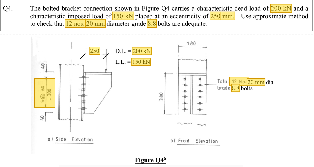
The question in short: A bracket is fixed by 12 M20 bolts in two rows of 6. It carries a dead load of 200 kN and an imposed load of 150 kN with an eccentricity of 250 mm. Decide whether the bolts are adequate when sheared and pulled at the same time.
What differs from the previous example of this type: Unlike Q3, the eccentricity here tips the bracket outwards, so the upper bolts are pulled. The bolts take shear and tension together, which needs one extra combined check.
| Given | Value and Unit |
|---|---|
| Loading | DL200, LL150 kN; eccentricity 250 mm |
| Bolts | 12 M20 bolts, Grade 8.8, in two rows; ; , |
| Layout | Six bolts per row, vertical spacing 5 @ 60 mm |
| Model | The lecturer takes the bottom as rotation reference and tension proportional to |
Yellow: values given in the question. The same values are marked where they are substituted in the steps below.
Orange box: values read directly from the Data File, the same values boxed orange in the lookup screenshots. A value interpolated between two table rows is a calculation, so it has no box.
Solution Route: Design force→direct shear →moment/squared-distance sum→top-bolt tension→individual capacities→interaction.
This browser cannot show the 3D model.
The load passes from the bracket through 12 bolts into the column flange. The bolts take two actions at once: direct shear, and tension from the moment of the eccentric load. Each is checked alone, then together.
- Design loadat 250 mm eccentricity
- Bolt shear (shared by 12)Demand 43.333 kNCapacity 91.875 kNper boltUtilisation 0.47
- Tension in the top rowDemand 98.485 kNCapacity 109.76 kNper boltUtilisation 0.90
- Shear and tension together (limit 1.4)Sum 1.369Limit 1.4closest to the limit
- Column flangeReceives the shear and tension from the bolts
- Step 1 · Design force
Why this step: The loads given have not yet been multiplied by load factors. Scaling them up first gives the design force the bolts must really resist.
All twelve bolts carry the group load here. Do not retain Q3's one-side division by 2.
New symbols in this step- , , : Total force, shear per bolt and tension per bolt; kN
- , : Unfactored dead and imposed loads; kN
- Step 2 · Direct shear
Why this step: The load pushes along the contact face and tries to cut each bolt across. This step finds how much of that force each bolt must resist.
Find demand per bolt using this problem's distribution assumption.
New symbols in this step- , : Bolt spacing along the force, mm; number of bolts
Where the numbers come from: from Step 1.
- Step 3 · Rotation geometry
Why this step: When the bracket tips outwards about its bottom, higher bolts are stretched more. The distance of each row from the bottom row is listed first, to share out the tension in the next step.
The bottom row, , gives no tension moment in this model; the other five levels have two bolts each, at 60, 120, 180, 240 and 300 mm above it (vertical spacing 60 mm).
- Step 4 · Maximum tension
Why this step: The top row is farthest from the bottom, so it is pulled the most. If the bolts in this row do not snap, those in the lower rows will not either.
Bolt tension moments balance external moment . Proportional distribution gives .
Where the numbers come from: from Step 1; from Step 3.
Load path · How the moment becomes tension in the boltsThe eccentric load turns the bracket about the bottom row of bolts. The farther a bolt is from this line, the harder it is pulled, so the tensions form a triangle with the largest at the top row. The moments of all the bolt tensions about the line add up to the applied moment Fe. - Step 5 · Calculate both resistances separately
Why this step: Being cut across and being pulled apart are two different ways for a bolt to fail, each with its own strength. So two capacities are worked out.
uses ; course uses 0.8ptAs. The 0.8 does not reduce the external load.
New symbols in this step- , , , : Shear, bolt bearing, plate bearing and plate tension resistances; kN
- , , , : Corresponding course design strengths; N/mm²
Units: and are in N/mm² and is in mm², so each product is in N; both lines divide by 1000 to give kN.
Data file lookup · Data Page 4 · Bolt tables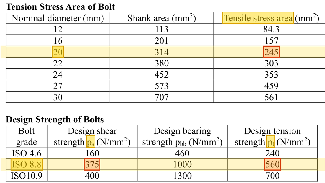
The M20 row gives tensile stress area ; the Grade 8.8 row gives and .Yellow: given parameter, row or columnOrange: value read from the table, boxed orange in the text too - Step 6 · Check individual limits first
Why this step: First confirm that shear alone does not cut the bolt and tension alone does not snap it. If either one fails, the bolt is already inadequate.
43.333<91.875 and 98.485<109.76, so both individual checks pass.
- Step 7 · Then check interaction
Why this step: The same bolt is sheared and pulled at once, and each force uses up part of its strength. So the two utilisations are added together and checked.
Do not omit interaction because the separate checks pass. The course limit 1.4 belongs specifically to this bolt expression.
Where the numbers come from: from Step 2; from Step 5; from Step 4; from Step 5.
Load path · Checking shear and tension togetherThe horizontal axis is the share used by shear and the vertical axis the share used by tension. The green area is the allowed range: neither above 1, and their sum not above 1.4. The point for this example (red) is inside, but close to the sloping edge.
The displayed shear, tension and interaction checks all pass, with interaction close to its limit. Do not transfer 1.4 to column expressions requiring ≤1.
All the symbols of this example
| Symbols | Meaning and Units |
|---|---|
| , , | Total force, shear per bolt and tension per bolt; kN |
| , , , | Shear, bolt bearing, plate bearing and plate tension resistances; kN |
| , , , | Bolt diameter, hole diameter, end distance along force and clear hole spacing; mm |
| , , , | Bolt effective shear area and gross/net/effective plate areas; mm² |
| , , , | Corresponding course design strengths; N/mm² |
| , | Unfactored dead and imposed loads; kN |
| , | Bolt spacing along the force, mm; number of bolts |
Video positions: 26 September 02:10:00 · 26 September 02:15:00 · 26 September 02:20:00