Q3: combine shear at each bolt in an eccentric in-plane group (In-plane Eccentric Bolts)
Task: Use bolt coordinates to find the furthest-bolt resultant and trace the lecturer's correction from total to one-side loading.
Go straight to Step 1 ↓Design flow for this type of question: Ordinary bolted connection →
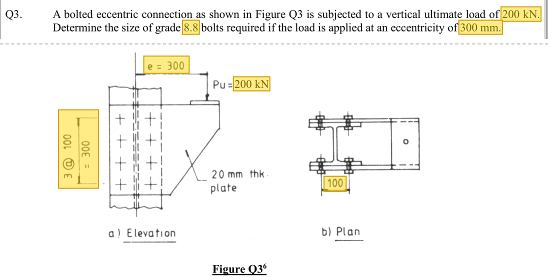
The question in short: A bracket carries an ultimate load of 200 kN, shared by two matching side plates. Each side has 8 bolts, and the load acts 300 mm from the centre of the bolt group. Find the bolt with the largest force and decide whether M16 bolts are adequate.
What differs from the previous example of this type: Unlike the earlier tension joints, the load does not pass through the centre of the bolt group, so it tries to turn the group. Each bolt gets a different force, and the worst one must be found.
| Given | Value and Unit |
|---|---|
| Whole bracket | 200 kN ultimate load; symmetrical side plates |
| One-side arrangement | Eight bolts in two rows, 100 mm apart; vertical spacing 3 @ 100 mm |
| Eccentricity | 300 mm from one-side group centroid to load line |
| Bolts | Grade 8.8; try M16, , |
Yellow: values given in the question. The same values are marked where they are substituted in the steps below.
Orange box: values read directly from the Data File, the same values boxed orange in the lookup screenshots. A value interpolated between two table rows is a calculation, so it has no box.
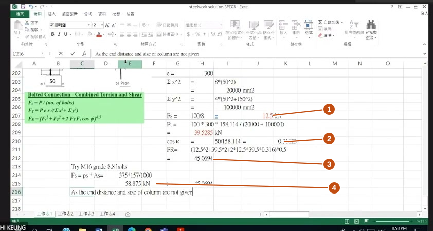
Solution Route: Allocate between sides→centroid/squared-distance sum→direct shear →torsional shear →vector combination→bolt selection.
This browser cannot show the 3D model.
The 200 kN is first shared equally by the two bracket plates. The 100 kN on each plate misses the centroid of the bolt group, so each bolt takes a torsional shear as well as the direct shear.
- Ultimate load200 kN, 100 kN per bracket plate
- Bracket plate: eccentricity gives a torque
- Bolts: direct shear12.5 kN per bolt
- Bolts: torsional shear39.528 kN at a corner bolt
- Resultant on a corner bolt (M16, single shear)Demand 45.069 kNCapacity 58.875 kNper boltUtilisation 0.77
- Column flangeThe question gives no data for a bearing check
- Step 1 · Choose the analysed object first
Why this step: The two side plates are alike, so each takes half the load. Fixing the load on one side first stops every bolt force from being doubled later.
The whole bracket carries 200 kN, but the eight bolts drawn are one side, so use 100 kN. The lecturer initially obtains larger components with 200 kN, then corrects to 100 kN.
- Step 2 · Direct shear
Why this step: First treat the load as if it acted at the centre of the group, simply pushing the plate along. This is the first part of the force on each bolt; the turning part is added later.
Eight identical bolts share direct force equally, each acting parallel to the external force.
New symbols in this step- , , : Total force, shear per bolt and tension per bolt; kN
- , : Bolt spacing along the force, mm; number of bolts
- Step 3 · Calculate group geometry from coordinates
Why this step: A load away from the centre makes the plate turn about that centre. Bolts farther out resist turning more effectively, so the position of each bolt must be measured.
Bolt coordinates are measured from the centroid of the group: the rows are 100 mm apart, so ; the vertical spacing is 3 @ 100 mm, so and ±150 mm. Squares of negative coordinates are positive.
- Step 4 · Add squared vertical distances
Why this step: The sum of squared distances measures how well the whole group resists turning. The larger it is, the smaller the turning force on each bolt.
Four bolts have ||=150 and four ||=50. Sum squared distances; do not square the sum of distances.
Where the numbers come from: from Step 3.
- Step 5 · Furthest-corner radius
Why this step: When the group turns, the bolt farthest from the centre moves the most and takes the largest turning force. So the corner bolts are the ones to check.
Find from the right triangle. It determines torsional-shear magnitude.
New symbols in this step- , , : Eccentric moment kNmm, radius mm, sum of squared distances mm²
- Step 6 · Torsional component
Why this step: This is the extra force on the bolt caused by the load being off-centre. The larger the eccentricity, the larger the turning moment and the force on the corner bolt.
. Bolt torsional forces distribute according to radius. is perpendicular to that radius, not automatically parallel to the external force.
- Step 7 · Read the included angle
Why this step: The two forces point in different directions, so they cannot simply be added. The angle between them is found first so that they can be combined in the next step.
At the critical corner, the illustrated angle has . Other corners have different directions; inspect the arrows first.
Where the numbers come from: from Step 5.
- Step 8 · Combine demand
Why this step: The bolt really feels one combined force, and that is its shear demand. The closer the two forces are in direction, the larger the combined force.
Use the lecturer's vector combination, not 12.5+39.528.
Where the numbers come from: from Step 2; from Step 6; from Step 7.
Load path · Eccentric load = direct shear + torsional shearMoving the eccentric 100 kN to the centroid of the bolt group needs a torque to go with it. ② The direct shear is shared equally by the eight bolts; ③ the torque gives each bolt a force perpendicular to its radius, larger farther from the centroid; ④ the two are added as vectors bolt by bolt, and the corner bolts on the load side take the most. - Step 9 · Try M16
Why this step: This guards against the most heavily loaded bolt shearing off. If the worst bolt does not fail, the whole group is adequate in shear.
Effective area gives single-shear resistance 58.875, above maximum demand.
New symbols in this step- , , , : Shear, bolt bearing, plate bearing and plate tension resistances; kN
- , , , : Corresponding course design strengths; N/mm²
Units: is in N/mm² and is in mm², so the product is in N; dividing by 1000 gives kN, ready to compare with the combined force.
Data file lookup · Data Page 4 · Bolt tables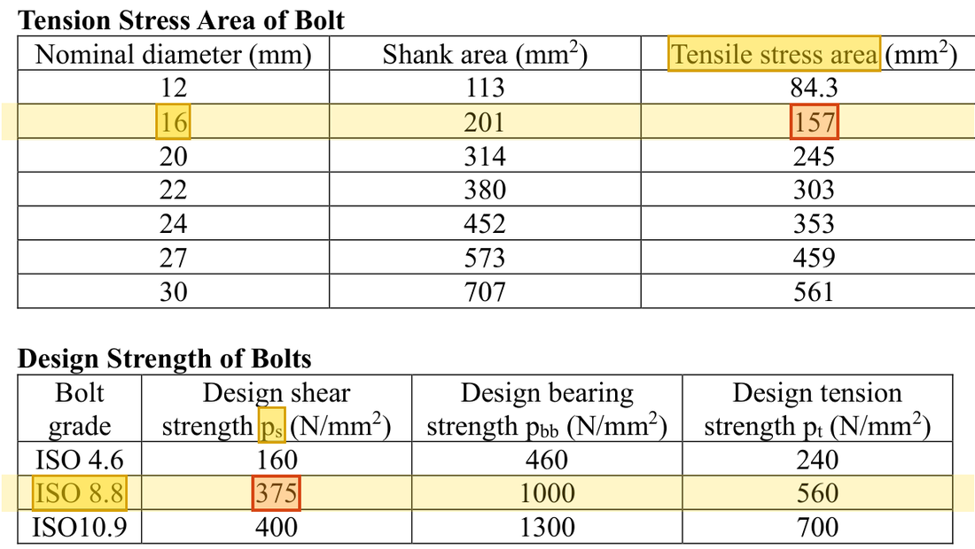
The M16 row gives tensile stress area ; the Grade 8.8 row gives .Yellow: given parameter, row or columnOrange: value read from the table, boxed orange in the text too - Step 10 · Retain the problem's scope
Why this step: A bolt that does not shear off can still crush the hole wall. Plate bearing needs the plate thickness and end distance, so the conclusion here covers shear only.
The lecturer states that end distances , column dimensions and other bearing data are absent. This completes bolt selection for the given shear demand only; it does not imply eccentric connections need no bearing check.
The distinction between whole-bracket and one-side loads is the key correction. M16 passes the displayed shear demand only. Plate bearing and complete detailing require further data.
All the symbols of this example
| Symbols | Meaning and Units |
|---|---|
| , , | Total force, shear per bolt and tension per bolt; kN |
| , , , | Shear, bolt bearing, plate bearing and plate tension resistances; kN |
| , , , | Bolt diameter, hole diameter, end distance along force and clear hole spacing; mm |
| , , , | Bolt effective shear area and gross/net/effective plate areas; mm² |
| , , , | Corresponding course design strengths; N/mm² |
| , , | Eccentric moment kNmm, radius mm, sum of squared distances mm² |
| , | Bolt spacing along the force, mm; number of bolts |
Video positions: 26 September 01:50:00 · 26 September 01:55:00 · 26 September 02:00:00 · 26 September 02:05:00