750 kN double-cover splice: separate capacity and spacing (Double-cover Splice)
Task: Follow the lecturer's trial sequence for bolt count and bearing, then identify why transverse spacing must change.
Go straight to Step 1 ↓Design flow for this type of question: Ordinary bolted connection →
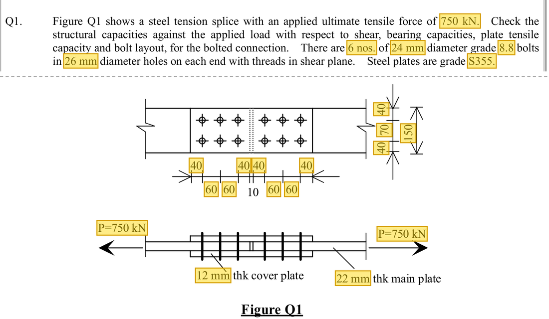
The question in short: Two main plates, 150 mm wide and 22 mm thick, are joined end to end by two 12 mm cover plates with 6 M24 bolts at each end. The ultimate pull is 750 kN. Decide whether the bolts, plate bearing and main plate are adequate, and whether the hole spacing meets the rules.
What differs from the previous example of this type: Compared with the previous example: each bolt passes through the main plate and two cover plates, so it is in double shear; the load is already ultimate, so no load factor is applied; hole spacing is also checked.
| Given | Value and Unit |
|---|---|
| Main/cover plates | Main plate 150 mm wide, 22 mm thick; two cover plates, 12 mm each; S355 plates |
| Bolts | Six M24 bolts at each end, 26 mm holes, Grade 8.8; |
| Loading | 750 kN, already ultimate tension |
| Geometry | Longitudinal pitch 60 mm; end distance 40 mm; transverse spacing 70 mm |
| Strengths | ; , , , , |
Yellow: values given in the question. The same values are marked where they are substituted in the steps below.
Orange box: values read directly from the Data File, the same values boxed orange in the lookup screenshots. A value interpolated between two table rows is a calculation, so it has no box.
Solution Route: Identify double shear; find governing bolt/plate bearing ; estimate bolt count from resistance; finally check the arrangement.
This browser cannot show the 3D model.
The 750 kN passes from the left main plate through the bolts into the two cover plates, then through the bolts on the other side into the right main plate. The two halves are in series, so each half carries the full 750 kN.
- Ultimate tension750 kN (already an ultimate load)
- Main plate in tension (net section)Demand 750 kNCapacity 818.2 kNUtilisation 0.92 · closest to the limit
- Bearing on the main plate (6 bolts)Demand 750 kNCapacity 1452 kNUtilisation 0.52
- Bolts in double shearCapacity 264.75 kN per bolt, more than the 242 kN in plate bearing, so it does not govern
- Two cover platesEach takes half; together 24 mm, thicker than the 22 mm main plate
- Other half of the jointThe same six bolts return the force to the right main plate
- Step 1 · Do not factor again
Why this step: An ultimate load already includes the load factors; applying them again would overstate the demand. All later checks use this force directly.
750 kN is ultimate load. The whole force passes successively through the left half-joint, covers and right half-joint.
- Step 2 · Double-shear resistance per bolt
Why this step: The main plate sits between two covers, so the bolt must be cut at two faces at once to fail. Its capacity is therefore twice that of single shear.
Each bolt has two shear planes, hence ×2. This factor does not represent the two half-joints.
New symbols in this step- , , , : Shear, bolt bearing, plate bearing and plate tension resistances; kN
- , , , : Corresponding course design strengths; N/mm²
Units: in N/mm² times in mm² gives N, then times the number of shear planes; dividing by 1000 gives kN.
Data file lookup · Data Page 4 · Bolt tables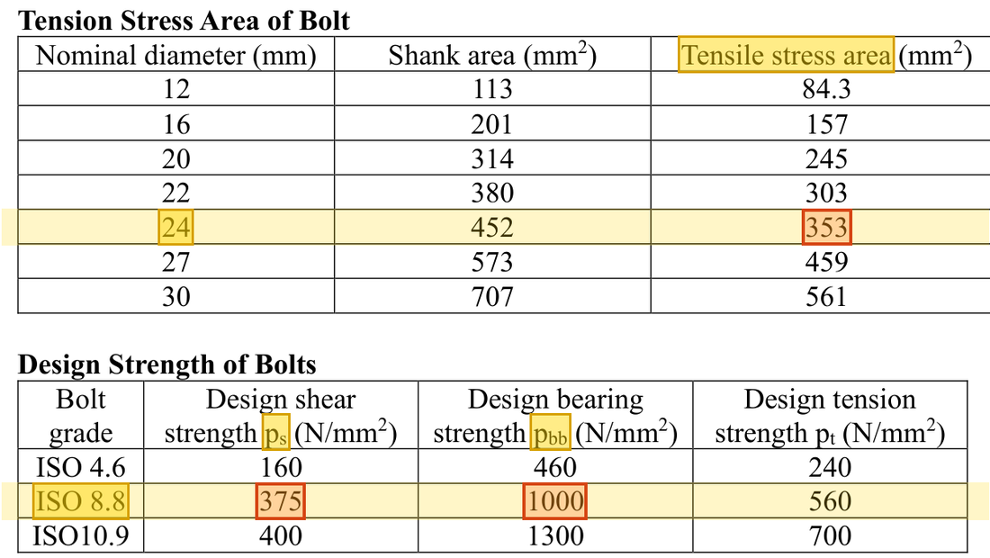
The M24 row gives tensile stress area ; the Grade 8.8 row gives and .Yellow: given parameter, row or columnOrange: value read from the table, boxed orange in the text too - Step 3 · Select bearing thickness
Why this step: The main plate pulls one way and the two covers together pull the other way. The thinner side gives the bolt less contact area, so the bolt is more likely to be crushed there.
Compare the 22 mm main plate with combined covers of 24 mm and use 22 mm. Substitute for M24 and .
Units: and are in mm and is in N/mm², so the product is in N; dividing by 1000 gives kN.
- Step 4 · Calculate clear spacing first
Why this step: When the bolt pushes on the hole wall, what must tear is the steel left between two holes, not the full centre-to-centre length.
60 mm is hole-centre spacing; clear spacing is 60−26.
New symbols in this step- , , , : Bolt diameter, hole diameter, end distance along force and clear hole spacing; mm
- , : Bolt spacing along the force, mm; number of bolts
- Step 5 · Calculate plate-bearing bounds individually
Why this step: This guards against the main plate being crushed or torn near the bolt holes. Whichever value is smallest is the way the plate would fail first.
Standard holes use . The four values correspond to hole-wall bearing, end distance , clear hole spacing and the upper cap.
New symbols in this step- , : Hole-type and effective-area factors; dimensionless
Where the numbers come from: from Step 4.
Units: All lengths and the thickness are in mm; , and are in N/mm². Each product is in N, and dividing by 1000 gives kN.
Data file lookup · Data Page 4 · Bearing of connected part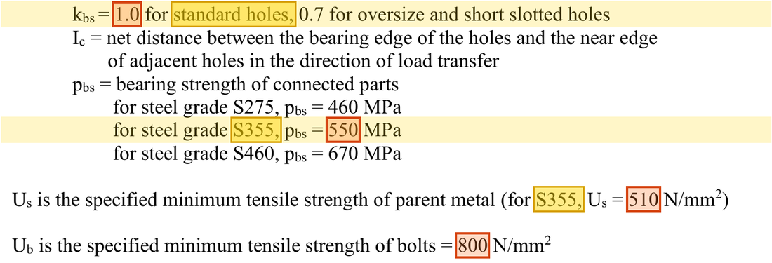
Standard holes give . For S355 plate the bearing strength is and ; for the bolt .Yellow: given parameter, row or columnOrange: value read from the table, boxed orange in the text too Load path · Four limits on plate bearingThe bolt presses on the hole wall, and the plate can fail in four ways: the hole wall crushes, the bolt tears out through the plate end, the plate tears between two holes, and there is a cap set by the bolt strength. The smallest of the four values is used (red frame). - Step 6 · Identify the governing mode
Why this step: The force each bolt can pass on is set by the weakest item. Dividing the total pull by it gives the least number of bolts needed.
Per bolt: shear 264.75, bolt bearing and plate bearing . Use 242 for this comparison.
New symbols in this step- , , : Total force, shear per bolt and tension per bolt; kN
Where the numbers come from: from Step 5.
- Step 7 · Integer bolt count and the given layout
Why this step: A bolt count cannot be a fraction, so it is rounded up. The actual number on the drawing times the capacity per bolt is then confirmed to exceed the pull.
Resistance alone requires at least four bolts. The lecturer retains six per half-joint as drawn. This does not authorise simply deleting two, because layout and other checks would also change.
Where the numbers come from: from Step 5.
- Step 8 · Longitudinal pitch check
Why this step: Holes too close leave little steel between them and make fitting awkward. Holes too far apart may let the plates gape between bolts. So spacing has a lower and an upper limit.
Minimum equals the provided 60 mm. Maximum is 144 mm for a 12 mm cover; 60 mm is also below it.
- Step 9 · Transverse spacing still fails
Why this step: Enough capacity does not make the layout acceptable. Holes too close across the force also leave too little steel between them, so the spacing is increased.
The course requires at least perpendicular to the force. The shown 70 mm is insufficient; the lecturer changes it to 75 mm.
- Step 10 · Review the drawing after revision
Why this step: The plate width stays the same, so moving the holes apart leaves less steel between hole and plate edge. Too small an edge distance can let the edge tear, so the layout is looked at again.
Changing spacing affects edge distances, plate width or clear distances. Recheck the actual arrangement; changing one displayed number does not complete the design.
- Step 11 · Main-plate net section
Why this step: This guards against the main plate being pulled apart along a row of holes. Two holes remove steel at this section, making it the weakest place in the plate.
The main plate is thinner than the combined covers, 22<24 mm, so it is checked here. Deduct two 26 mm holes from the 150 mm width.
New symbols in this step- , , , : Bolt effective shear area and gross/net/effective plate areas; mm²
- Step 12 · Effective area
Why this step: The section through the holes is only a short length, and steel there can develop a little more than . raises the net area slightly to allow for this.
Apply , capped at gross area .
Where the numbers come from: from Step 11.
Data file lookup · Data Page 2 · Tension members
for S355.Yellow: given parameter, row or columnOrange: value read from the table, boxed orange in the text too - Step 13 · Main-plate tension resistance
Why this step: Area times strength gives the pull the main plate can take before it breaks at the holes. Since it exceeds the demand, the plate will not break.
Use for 22 mm thickness.
Where the numbers come from: from Step 12.
Units: is in N/mm² and is in mm², so the product is in N; dividing by 1000 gives kN.
Data file lookup · Data Page 1 · Design strength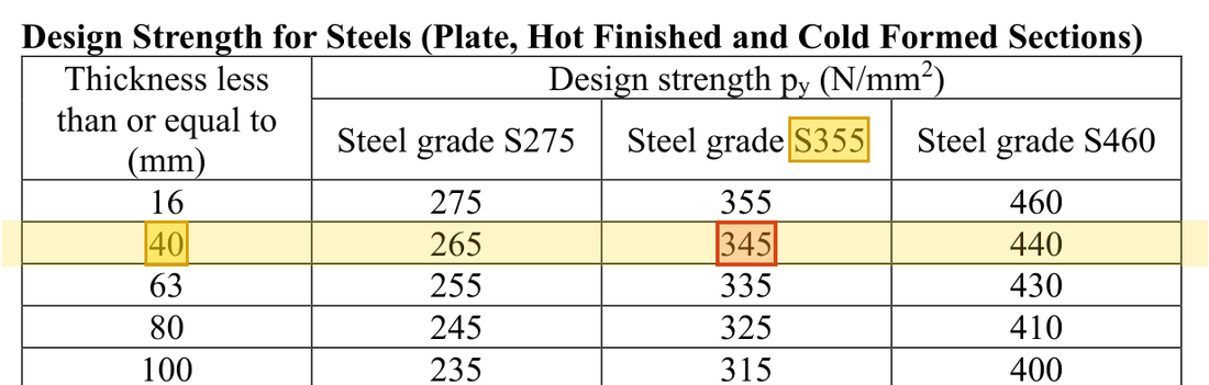
Main plate 22 mm thick: the row, S355 column gives . How the grade and thickness choose this row →Yellow: given parameter, row or columnOrange: value read from the table, boxed orange in the text too
This example distinguishes adequate resistance from compliant hole detailing. Main-plate net-section resistance 818.2 kN exceeds 750 kN, so main-plate tension is also adequate.
All the symbols of this example
| Symbols | Meaning and Units |
|---|---|
| , , | Total force, shear per bolt and tension per bolt; kN |
| , , , | Shear, bolt bearing, plate bearing and plate tension resistances; kN |
| , , , | Bolt diameter, hole diameter, end distance along force and clear hole spacing; mm |
| , , , | Bolt effective shear area and gross/net/effective plate areas; mm² |
| , , , | Corresponding course design strengths; N/mm² |
| , | Plate and bolt ultimate tensile strengths; N/mm² |
| , | Hole-type and effective-area factors; dimensionless |
| , | Bolt spacing along the force, mm; number of bolts |
Video positions: 19 September 02:20:00 · 19 September 02:25:00 · 19 September 02:35:00 · 19 September 02:40:00 · 19 September 02:59:53