65×50×8 angle: centroid and unequal weld lengths (Unequal Weld Lengths)
Task: Follow the lecturer from total force to weld length, then divide between sides by moment equilibrium.
Go straight to Step 1 ↓Design flow for this type of question: Fillet-welded connection →
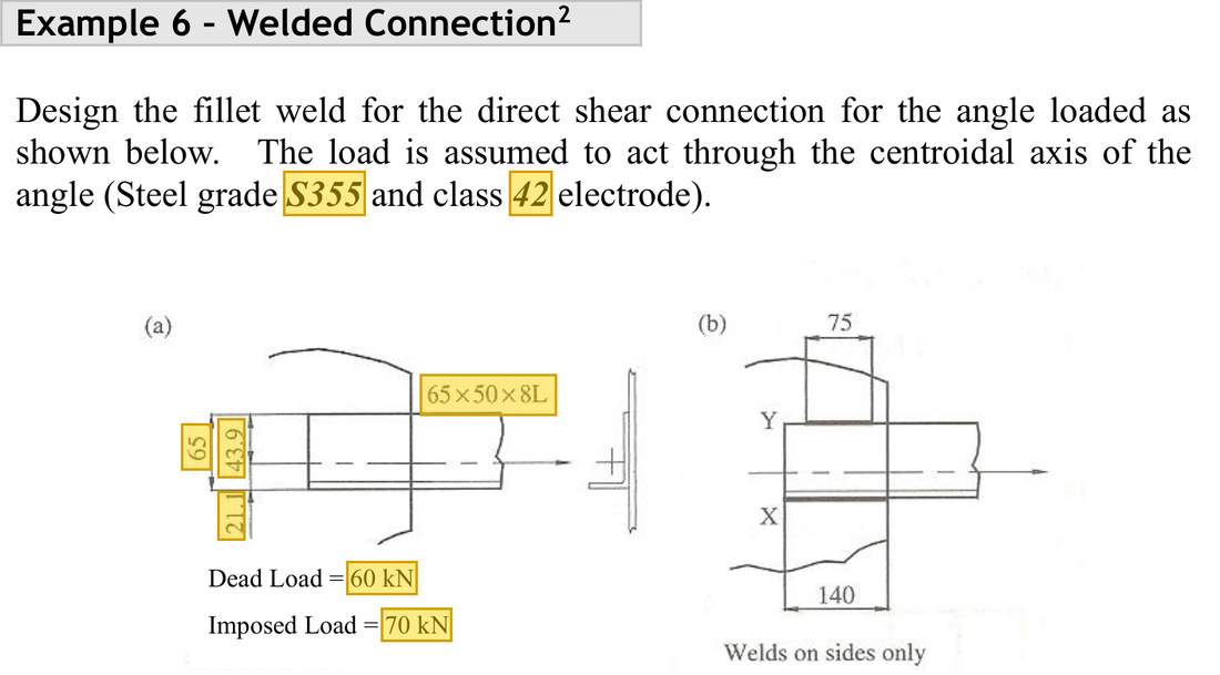
The question in short: A 65×50×8 angle carries a tension from a dead load of 60 kN and an imposed load of 70 kN, and is fixed with 6 mm fillet welds. Its centroid is 21.1 mm and 43.9 mm from the two edges. Decide the weld length on each side.
What differs from the previous example of this type: The method is the same as the previous example, but here only the welds are designed and the tension capacity of the angle is not worked out. The angle size, leg size and centroid distances all differ, so the earlier figures cannot be reused.
| Given | Value and Unit |
|---|---|
| Question data | DL 60, LL 70 kN; 65×50×8 angle, S355 |
| Welding | Try a 6 mm fillet weld; class 42 electrode, |
| Centroid | From the figure: connected width 65 mm; centroid 21.1 and 43.9 mm from the two edges |
Yellow: values given in the question. The same values are marked where they are substituted in the steps below.
Orange box: values read directly from the Data File, the same values boxed orange in the lookup screenshots. A value interpolated between two table rows is a calculation, so it has no box.

Solution Route: →resistance per millimetre→total effective length →side allocation→end allowance→actual lengths.
This browser cannot show the 3D model.
The tension acts along the centroid line. Side is only 21.1 mm from the centroid, so its weld carries more force and is longer.
- Design tension
- Angle 65×50×8Carries the force to the two welds; this example sizes the welds only
- Weld on side (nearer the centroid)Needs 138.07 mmUse 140 mm
- Weld on side (farther away)Needs 72.59 mmUse 75 mm
- Connecting plateReceives the whole 196 kN from the two welds
- Step 1 · Design force and resistance per millimetre
Why this step: Two figures are prepared here: the factored tension the welds must pass on, and the force the throat of each millimetre of weld can carry. Dividing one by the other in the next step gives the weld length.
Convert leg to throat with 0.7. Keep force and unit-length resistance consistently in kN.
New symbols in this step- , : Applied force; kN
- , : Unfactored dead and imposed loads; kN
Units: Leg size in mm times 0.7 gives the throat in mm; times in N/mm² gives N per mm. Dividing by 1000 gives kN/mm, matching the tension in kN.
Data file lookup · Data Page 3 · Design strength of fillet weld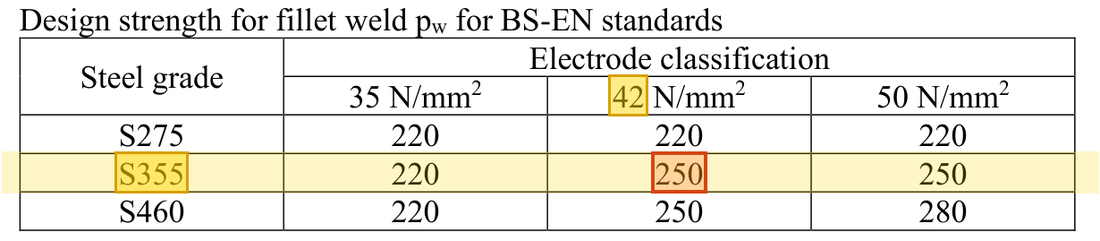
For S355 steel with class 42 electrodes the fillet weld design strength is .Yellow: given parameter, row or columnOrange: value read from the table, boxed orange in the text too - Step 2 · Total effective length
Why this step: If the welds together have less load-carrying length than this, the throat will shear. It is the total that the next step shares between the two sides.
This is the total of both lines, not each line.
New symbols in this step- , : Weld design strength N/mm²; resistance per millimetre kN/mm
- , : Actual or effective weld length; mm, as identified by each step
- Step 3 · Establish equilibrium
Why this step: The turning effects of the two weld forces about the centroid must cancel. Then their combined force lines up with the pull in the angle and the joint gets no extra twist.
Side is nearer the centroid, with lever arm 21.1, so it carries more force. For equal leg sizes , force is proportional to effective length .
- Step 4 · Solve the two lengths
Why this step: The solution gives a clearly longer weld on side , matching the fact that it is nearer the centroid and takes more force. The two lengths still add up to the total effective length.
Substitute into the two simple algebraic equations to obtain unequal lengths.
New symbols in this step- , : Distances from the two welds to the angle centroid; mm
Where the numbers come from: from Step 2.
Load path · How the two welds share the tensionThe tension acts on the centroid line. The moments of the two weld forces about the centroid must cancel, so side , nearer the centroid, carries more force and needs the longer weld. Lengths shown are effective lengths, before adding . - Step 5 · Convert to actual lengths
Why this step: The calculated values are effective lengths only. A short piece at each end of a weld is not counted, so each length is increased and then rounded up, never down.
Add to each. The lecturer selects 140 and 75 mm respectively.
New symbols in this step- , : Leg size and effective throat; mm, with in this course
- Step 6 · Detailing comparison
Why this step: If a weld is too short, or short compared with the spacing between the two welds, the force cannot spread evenly into the angle. The chosen lengths are therefore compared with the detailing requirements.
Provided lengths must also satisfy course minimum-length and weld-spacing conditions. A 12 mm end allowance does not replace every detailing check.
The centroid distances 21.1/43.9 differ from the later 65×50×6 double-angle values 20.4/44.6. Equal nominal width does not justify copying centroid positions.
All the symbols of this example
| Symbols | Meaning and Units |
|---|---|
| , | Leg size and effective throat; mm, with in this course |
| , | Weld design strength N/mm²; resistance per millimetre kN/mm |
| , | Actual or effective weld length; mm, as identified by each step |
| , | Applied force; kN |
| , | Eccentricity and weld-group corner radius; mm |
| , | Unfactored dead and imposed loads; kN |
| , | Distances from the two welds to the angle centroid; mm |
Video positions: 26 September 02:40:00 · 26 September 02:45:00