Connections: four bolt checks plus an eccentric weld
The connection question usually has two parts: (a) angles or plates joined by a group of bolts (about 17 marks) and (b) a weld group or an eccentrically loaded bolt group (about 13 marks). Each formula is short; the real skill is counting correctly — how many bolts, how many shear planes, which plate is thinnest.
What does this question test? Always examined
| Year | Part (a) | Part (b) |
|---|---|---|
| 2024 | two angles bolted back-to-back: bolt shear, bolt bearing, angle bearing, angle tension | four-sided rectangular weld under an eccentric load: find the weld size |
| 2023 FT | two bolted angles: the same four checks | welded UB bracket: web welds take shear, flange welds take the moment |
| 2023 PTE | two welded angles: tension and sharing the weld lengths | ten-bolt bracket: bolts in shear and tension together |
| 2022 | double-cover bolted splice: the same four checks | four-sided rectangular weld under an eccentric load |
First picture it: how can a bolted joint fail? Often examined
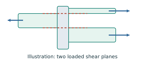
The four bolt checks (part (a)) Always examined
Look up the data in Data File p.4 first. The course usually uses Grade 8.8 bolts:
| Data | M20 | M24 | M27 | Note |
|---|---|---|---|---|
| tensile stress area (mm²) | 245 | 353 | 459 | used for shear and tension |
| hole diameter (mm) | 22 | 26 | 30 | ; larger bolts |
Grade 8.8: , , , . S355 plate: , , .
Bolt shear: will the bolt be cut?
Count the planes on the side view: two plates lapped = 1 plane (single shear); a middle plate sandwiched between two plates = 2 planes (double shear).
Bolt bearing: will the bolt itself be crushed by the hole edge?
Use the “weakest side” for : in double shear compare the middle plate with the sum of the two outer plates and take the smaller.
Plate bearing: will the plate around the hole crush or tear out?
= end distance (hole centre to plate end, along the force); = clear gap between holes = pitch − . Write all three numbers, then take the smallest.
Tension: will the plate or angle tear across the holes?
is the number of holes on one cross-section line, not the total number of bolts. When an angle is connected by one leg only, the outstanding leg () cannot work fully, so it is reduced:
Connection in single angle, bolted 0.5 single angle, welded 0.3 double angles (both sides of a gusset), bolted 0.25 double angles (both sides of a gusset), welded 0.15 For the angle areas, share the corner equally between the legs: connected leg , outstanding leg .
Understanding map
Bolted joint: four routes, and the weakest one wins
The four checks (bolt shear, bolt bearing, angle bearing, angle tension) are four separate routes that meet at the weakest link. Watch the counting boxes at the top: the number of bolts, shear planes and plate thicknesses feed almost every route. The values are from 2024 BQ2(a).
- From the question
- From the tables
- Worked out
- Capacity
- Check
- marks are often lost here
Text version (in working order)
From the question
Angle size
The 125 mm leg is bolted to the UC web (connected leg); the 75 mm leg sticks out (outstanding leg).
Needs (upstream)— (a starting value)
Used for (downstream), Leg areas
From the question
, Pitch, end distance
Pitch 80 mm (hole centre to hole centre); end distance 50 mm (hole centre to the angle end, along the force).
Needs (upstream)— (a starting value)
Used for (downstream) Clear gap between holes ③ Angle bearing
From the tablesWhere marks are lost
, , M20 Grade 8.8 bolt
Diameter is for bearing; hole diameter for net area and clear gaps; for shear.
2024 BQ2(a)
Where it comes from: Data File p.4.
Needs (upstream)— (a starting value)
Used for (downstream) ① Bolt shear ② Bolt bearing Clear gap between holes ③ Angle bearing Effective area
From the tables
, , S355 angle data
The angle material: for tension, and for bearing.
2024 BQ2(a)
Needs (upstream)— (a starting value)
Used for (downstream) ③ Angle bearing Effective area ④ Angle tension
Worked out
, Leg areas
Share the corner equally: each leg length minus , times .
Formula
2024 BQ2(a)
Needs (upstream) Angle size
Used for (downstream) Effective area ④ Angle tension
From the questionWhere marks are lost
, Bolts, shear planes
3 bolts; count the shear planes on the side view: angle / UC web / angle → 2 (double shear).
Needs (upstream)— (a starting value)
Used for (downstream) ① Bolt shear ② Bolt bearing ③ Angle bearing
From the questionWhere marks are lost
Plate thicknesses
The UC web in the middle is 12 mm; each angle is 8 mm.
Needs (upstream)— (a starting value)
Used for (downstream) ② Bolt bearing ③ Angle bearing
From the tablesWhere marks are lost
Outstanding-leg factor
Only one leg is connected, so the other cannot work fully. Double angles (both sides), bolted → 0.25.
Where it comes from: Single angle 0.5 / 0.3; double angles 0.25 / 0.15 (bolted / welded).
Needs (upstream)— (a starting value)
Used for (downstream) ④ Angle tension
Worked out
Clear gap between holes
The length of steel actually left between two holes.
Formula
2024 BQ2(a)
Needs (upstream), Pitch, end distance, , M20 Grade 8.8 bolt
Used for (downstream) ③ Angle bearing
Worked outWhere marks are lost
Effective area
Deduct the holes on one cross-section line from the connected leg, multiply by (not above the gross area), then add the other leg.
Formula
2024 BQ2(a)
Needs (upstream), Leg areas, , M20 Grade 8.8 bolt, , S355 angle data
Used for (downstream) ④ Angle tension
From the question
Design tension
The factored design tension (kN). The two angles share it: 175 kN each.
Needs (upstream)— (a starting value)
Used for (downstream) Weakest link
Capacity
① Bolt shear
Will a bolt be cut? One for every shear plane.
Formula
2024 BQ2(a)
Needs (upstream), , M20 Grade 8.8 bolt, Bolts, shear planes
Used for (downstream) Weakest link
Capacity
② Bolt bearing
Will the bolt itself be crushed by the hole edge? is the weaker side: the middle plate vs the two outer plates added, whichever is smaller.
Formula
2024 BQ2(a)
Needs (upstream), , M20 Grade 8.8 bolt Plate thicknesses, Bolts, shear planes
Used for (downstream) Weakest link
Capacity
③ Angle bearing
Will the angle around a hole crush or tear out? Write all three numbers and take the smallest; each angle has .
Formula
2024 BQ2(a)
Needs (upstream), , M20 Grade 8.8 bolt, , S355 angle data Plate thicknesses, Pitch, end distance Clear gap between holes, Bolts, shear planes
Used for (downstream) Weakest link
Capacity
④ Angle tension
Will the angle tear across the holes? The outstanding leg is reduced by .
Formula
2024 BQ2(a)
Needs (upstream) Effective area Outstanding-leg factor, Leg areas, , S355 angle data
Used for (downstream) Weakest link
Check
Weakest link
Each of the four must exceed the design tension; the joint is only as strong as the weakest — here, angle bearing.
2024 BQ2(a)
Needs (upstream) Design tension ① Bolt shear ② Bolt bearing ③ Angle bearing ④ Angle tension
Used for (downstream)— (the final conclusion)
Tour steps
1. Count first
Most connection marks are lost by miscounting: bolts, shear planes, the thinnest plate, pitch and end distance.
In this step Design tension, Bolts, shear planes Plate thicknesses, Pitch, end distance Angle size
2. Look up the data
Copy the bolt data () and the angle data () separately.
In this step, , M20 Grade 8.8 bolt, , S355 angle data
3. ① Bolt shear
Bolts × shear planes × .
In this step ① Bolt shear
4. ② Bolt bearing
is the smaller of the middle plate and the two outer plates added (12 mm).
In this step ② Bolt bearing
5. ③ Angle bearing: smallest of three
Work out the clear gap , write and take the smallest, 88 kN per bolt.
In this step Clear gap between holes ③ Angle bearing
6. ④ Angle tension
Leg areas → effective area → reduce the outstanding leg → .
In this step, Leg areas Effective area Outstanding-leg factor ④ Angle tension
7. The weakest link
The four routes meet here: 528 kN (angle bearing) is the smallest and still above 350 kN → adequate.
In this step Weakest link
Concept map
Net area and angles connected through one leg: why tension cannot use the whole area
Every recent connection question has 7 marks on angle tension in part (a). Two things shrink the usable area: holes remove steel, and when only one leg is connected the other cannot carry its full share. The two routes meet at .
- Cause
- Key idea
- Result
- What changes it
- How design deals with it
- Exam answer
- marks are often lost here
Text version (from cause to result)
Cause
Tension through a plate with holes
Bolt holes remove part of the plate, so the pull has to squeeze past them.
Comes from (upstream)— (a starting point)
Leads to (downstream) Net area: deduct holes on one fracture line
Cause
An angle connected through one leg
The bolts (or welds) hold only one leg (the connected leg); the other leg sticks out (the outstanding leg).
Comes from (upstream)— (a starting point)
Leads to (downstream)The outstanding leg joins in late, Share the corner between the legs
Key ideaWhere marks are lost
Net area: deduct holes on one fracture line
Along one fracture line across the force, deduct the holes it cuts: .
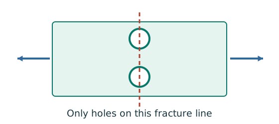
Comes from (upstream)Tension through a plate with holes
Leads to (downstream) Effective area: × K_e, but not above the gross area
What changes it
Use the hole, not the bolt
The hole is bigger than the bolt (M20 → 22 mm). Net area deducts the hole ; only bearing uses the bolt diameter .
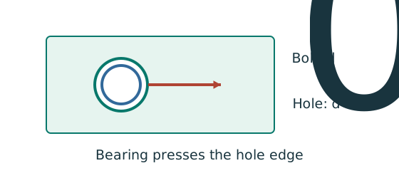
Comes from (upstream)— (a starting point)
Leads to (downstream) Effective area: × K_e, but not above the gross area
Key idea
The outstanding leg joins in late
The pull enters the connected leg first and reaches the outstanding leg only through the corner, so the outstanding leg cannot work fully. This is the idea of shear lag.
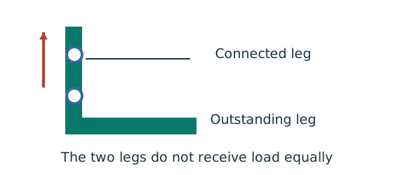
Comes from (upstream)An angle connected through one leg
Leads to (downstream) Deduct k·a₂ for the outstanding leg
What changes it
, Share the corner between the legs
The legs overlap at the corner, so do not count it twice: connected leg , outstanding leg .
Comes from (upstream)An angle connected through one leg
Leads to (downstream) Deduct k·a₂ for the outstanding leg
How design deals with itWhere marks are lost
Effective area: × K_e, but not above the gross area
The holes affect only a short length, where the steel breaks at its tensile strength rather than at yield, so the course lets the net area be multiplied by . The stronger the steel, the closer is to and the smaller : S275 → 1.2, S355 → 1.1, S460 → 1.0.
Formula
Comes from (upstream) Net area: deduct holes on one fracture line Use the hole, not the bolt
Leads to (downstream) Angle tension capacity
How design deals with itWhere marks are lost
Deduct k·a₂ for the outstanding leg
Single angle: bolted 0.5, welded 0.3; double angles (both sides of a gusset): bolted 0.25, welded 0.15. The deductions already allow for the connection eccentricity, so add no moment.
Comes from (upstream)The outstanding leg joins in late, Share the corner between the legs
Leads to (downstream) Angle tension capacity
Result
Angle tension capacity
Effective connected leg plus the outstanding leg, minus , times . Worked numbers: bolt calculation map.
Formula
Comes from (upstream) Effective area: × K_e, but not above the gross area Deduct k·a₂ for the outstanding leg
Leads to (downstream)Exam: write every area on its own line
Exam answer
Exam: write every area on its own line
Write and ; each line earns marks. Two angles: use the total area once, or one angle (half the force) and double it — never both.
Comes from (upstream) Angle tension capacity
Leads to (downstream)— (the last step)
Tour steps
1. Holes make the section smaller
Deduct the holes on one fracture line, using the hole diameter .
In this stepTension through a plate with holes Net area: deduct holes on one fracture line Use the hole, not the bolt
2. Effective area
.
In this step Effective area: × K_e, but not above the gross area
3. An angle connected through one leg
The pull enters the connected leg first and the other leg lags; the corner is shared between the legs.
In this stepAn angle connected through one legThe outstanding leg joins in late, Share the corner between the legs
4. Deduct
Single angle 0.5 / 0.3, double angles 0.25 / 0.15 (bolted / welded).
In this step Deduct k·a₂ for the outstanding leg
5. The two routes meet
, with every area on its own line.
In this step Angle tension capacityExam: write every area on its own line
Walkthrough: 2024 BQ2(a) (17 marks) Always examined
Given: two 125×75×8 S355 unequal angles back-to-back on both faces of the web (12.0 mm) of a 305×305×118 UC, three M20 Grade 8.8 bolts in 22 mm holes. Design tension 350 kN (already factored). Pitch 80 mm, end distance 50 mm.
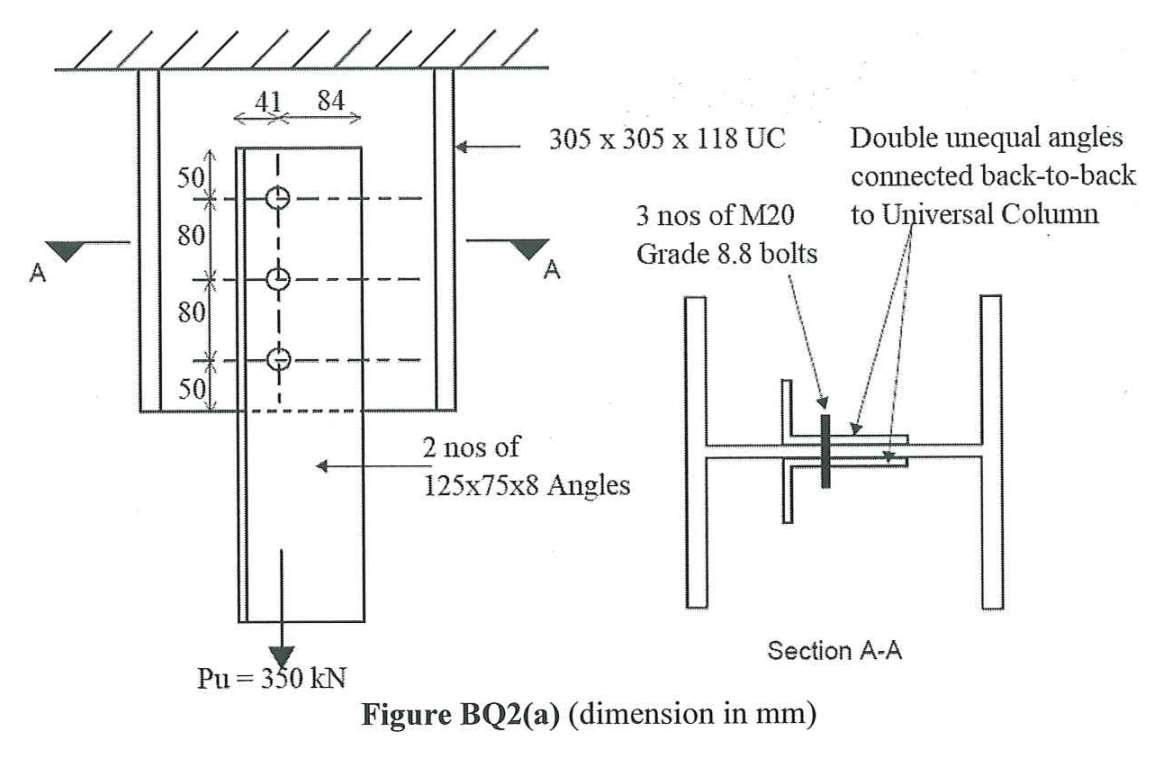
Past-paper walkthrough
(i) Bolt shear — 2 marks
Each bolt passes angle / UC web / angle → two shear planes (double shear).
Past-paper walkthrough
(ii) Bolt bearing — 2 marks
Middle UC web 12 mm; the two angles together 8 + 8 = 16 mm; take the smaller, 12 mm.
Past-paper walkthrough
(iii) Angle bearing — 6 marks
Each angle carries . , , .
Past-paper walkthrough
(iv) Angle tension — 7 marks
The pair gives . All four checks pass; the weakest is angle bearing (528 kN for the pair).
Full solution: 2024 BQ2(a).
Welds: understand the “throat” first Always examined
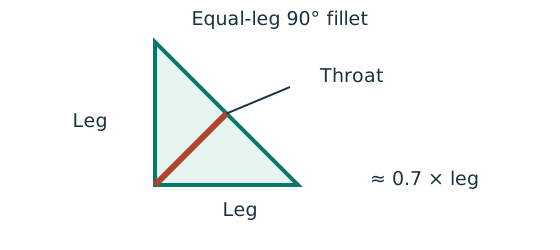
Example: 8 mm, S355, Class 42: .
Concept map
How a fillet weld carries load: throat, strength per millimetre and effective length
Every weld question starts from three ideas: a weld breaks at its narrowest part (the throat); how much each millimetre carries; and not all of the drawn length counts. Forgetting ×0.7 or −2s is the most common weld mistake.
- Cause
- Key idea
- Result
- What changes it
- How design deals with it
- Exam answer
- marks are often lost here
Text version (from cause to result)
Cause
The leg of a fillet weld
A fillet weld has a triangular cross-section. An “8 mm weld” means its leg .
Comes from (upstream)— (a starting point)
Leads to (downstream) The narrowest cut: the throat
Key ideaWhere marks are lost
The narrowest cut: the throat
The shortest cut through the weld is the throat of the triangle, about 0.7 × the leg, so that is where the weld breaks most easily.
Comes from (upstream) The leg of a fillet weld
Leads to (downstream) Strength per millimetre (kN/mm)
What changes itWhere marks are lost
Weld strength: steel + electrode
S355 with Class 42 electrodes → 250 N/mm² (“42” is not ); S275 → 220; S355 with Class 35 → 220.
Comes from (upstream)— (a starting point)
Leads to (downstream) Strength per millimetre (kN/mm)
What changes it
The ends are not fully formed
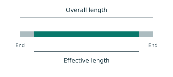
The start and end of every weld run are not fully formed and cannot be counted.
Comes from (upstream)— (a starting point)
Leads to (downstream) Effective length = actual − 2s
Key idea
Strength per millimetre (kN/mm)
Throat × weld strength is the force each millimetre of weld can carry. Handy S355/E42 values: 6 mm → 1.05; 8 mm → 1.40; 10 mm → 1.75 kN/mm.
Formula
Comes from (upstream) The narrowest cut: the throat Weld strength: steel + electrode
Leads to (downstream) Weld capacity
Key ideaWhere marks are lost
Effective length = actual − 2s
Deduct at each end of every run. When designing, go the other way: required effective length + , rounded up.
Formula
Comes from (upstream)The ends are not fully formed
Leads to (downstream)Size rules Weld capacity
What changes it
Size rules
Minimum effective length: the larger of and 40 mm; minimum leg by the thicker plate; maximum leg along a plate edge: thickness − 2 mm for plates ≥ 6 mm; in an end connection each longitudinal weld must be at least the transverse distance between the welds.
Comes from (upstream) Effective length = actual − 2s
Leads to (downstream)Where it is used
Result
Weld capacity
Strength per millimetre times effective length is what the run can carry.
Comes from (upstream) Strength per millimetre (kN/mm) Effective length = actual − 2s
Leads to (downstream)Where it is used
How design deals with it
Where it is used
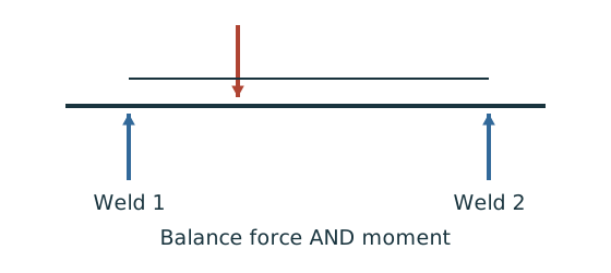
Eccentric weld groups: compare the resultant with (see the eccentric-weld map); welded double angles: share the two lengths by the centroid distances; UB brackets: web welds take shear, flange welds take the moment.
Comes from (upstream) Weld capacitySize rules
Leads to (downstream)Exam: q first, then length and size checks
Exam answer
Exam: q first, then length and size checks
E.g. ; ; , then check the size rules. In 2023 PTE the rule “length ≥ transverse spacing 200 mm” made the welds longer.
Comes from (upstream)Where it is used
Leads to (downstream)— (the last step)
Tour steps
1. A weld breaks at its narrowest
Leg → throat about .
In this step The leg of a fillet weld The narrowest cut: the throat
2. Strength per millimetre
Throat × ÷ 1000 → kN/mm. depends on both the steel and the electrode.
In this step Weld strength: steel + electrode Strength per millimetre (kN/mm)
3. Not all the length counts
Deduct at each end of every run, and meet the size rules.
In this stepThe ends are not fully formed Effective length = actual − 2sSize rules
4. Capacity and where it is used
, used for weld groups, double angles and brackets.
In this step Weld capacityWhere it is used
5. In the exam
Write , then the lengths, then the size checks.
In this stepExam: q first, then length and size checks
Eccentric weld group (the usual part (b)) Always examined
Design load and eccentricity
Length and “line” inertia of the weld (rectangle wide, high)
Direct shear, shared equally along the weld
Twist force at the furthest corner ()
Combine at the corner where the vertical twist adds to the direct shear
Weld size, rounded up
Understanding map
Eccentric weld: “straight down” plus “twist”, combined at the furthest corner
The load is off the weld centre, so the weld carries two things at once: direct shear shared equally, and extra force at the corners from the twist. The two routes meet at , which sets the weld size. The values are from 2024 BQ2(b).
- From the question
- From the tables
- Worked out
- Demand
- Check
- marks are often lost here
Text version (in working order)
From the question
, Dead, imposed load
The unfactored loads (kN).
Needs (upstream)— (a starting value)
Used for (downstream) Design load
From the question
Weld rectangle
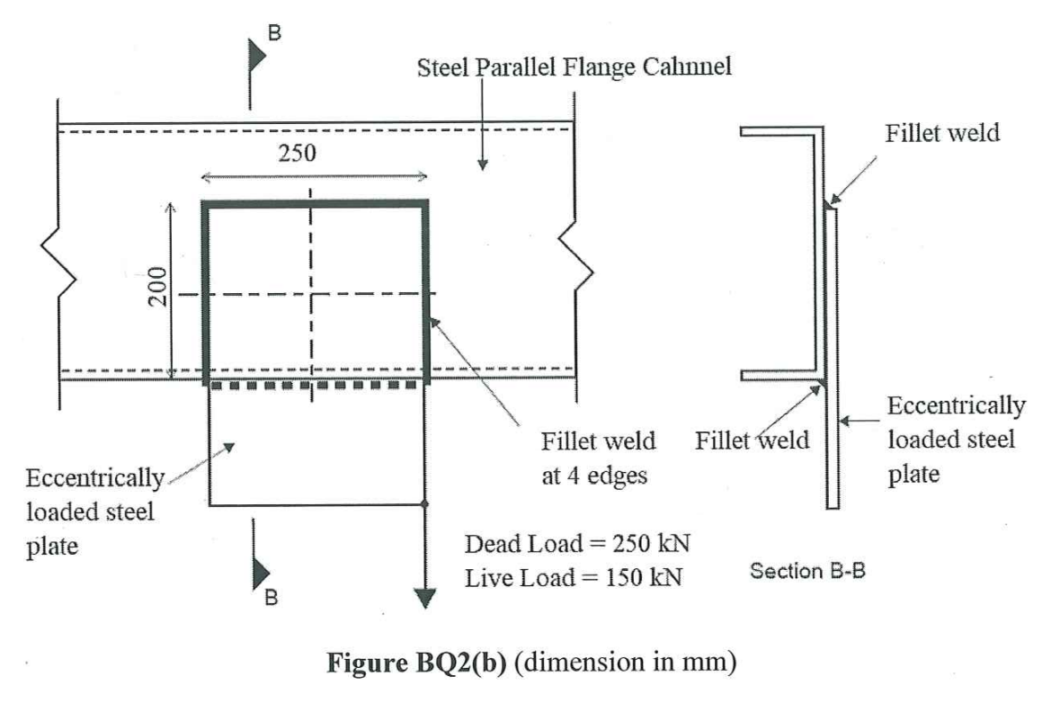
The four welds form a rectangle wide and high (mm). Treat the weld as a line; the empty middle is not weld.
Needs (upstream)— (a starting value)
Used for (downstream) Eccentricity Total weld length Polar inertia of the weld line, Furthest corner
From the question
Load position
The load acts on the line of the right-hand weld.
Needs (upstream)— (a starting value)
Used for (downstream) Eccentricity
DemandWhere marks are lost
Design load
Dead × 1.4, imposed × 1.6.
Formula
2024 BQ2(b)
Needs (upstream), Dead, imposed load
Used for (downstream) Twisting moment Direct shear per mm
Worked outWhere marks are lost
Eccentricity
Measured from the weld centroid to the load line. A rectangle’s centroid is in the middle, so .
2024 BQ2(b)
Needs (upstream) Weld rectangle Load position
Used for (downstream) Twisting moment
Demand
Twisting moment
The off-centre load tries to turn the plate — like a spanner: the further your hand, the bigger the twist.
2024 BQ2(b)
Needs (upstream) Design load Eccentricity
Used for (downstream) Twist: vertical part Twist: horizontal part
Worked out
Total weld length
All four sides added. Direct shear is shared equally over every millimetre.
Formula
2024 BQ2(b)
Needs (upstream) Weld rectangle
Used for (downstream) Direct shear per mm
Worked outWhere marks are lost
Polar inertia of the weld line
How well the weld loop resists twisting. The weld is a line, so the unit is mm³.
Formula
2024 BQ2(b)
Needs (upstream) Weld rectangle
Used for (downstream) Twist: vertical part Twist: horizontal part
Worked out
, Furthest corner
The corner furthest from the centroid is twisted hardest: , .
Needs (upstream) Weld rectangle
Used for (downstream) Twist: vertical part Twist: horizontal part
Demand
Direct shear per mm
The load pulls “straight down”, shared equally along the whole weld.
Formula
2024 BQ2(b)
Needs (upstream) Design load Total weld length
Used for (downstream) Resultant per mm
Demand
Twist: vertical part
The twist force at the corner, vertical part (uses ).
2024 BQ2(b)
Needs (upstream) Twisting moment, Furthest corner Polar inertia of the weld line
Used for (downstream) Resultant per mm
Demand
Twist: horizontal part
The twist force at the corner, horizontal part (uses ).
2024 BQ2(b)
Needs (upstream) Twisting moment, Furthest corner Polar inertia of the weld line
Used for (downstream) Resultant per mm
From the tablesWhere marks are lost
Weld design strength
S355 with Class 42 or 50 electrodes → 250 N/mm²; S275 → 220; S355 with Class 35 electrodes → 220.
Where it comes from: Data File p.3.
Needs (upstream)— (a starting value)
Used for (downstream) Required leg size Weld chosen
DemandWhere marks are lost
Resultant per mm
At the corner where the twist adds to the direct shear: add the vertical parts first, then combine with the horizontal part by Pythagoras.
Formula
2024 BQ2(b)
Needs (upstream) Direct shear per mm Twist: vertical part Twist: horizontal part
Used for (downstream) Required leg size Weld chosen
Worked out
Required leg size
The narrowest part, the throat, is about 0.7 × the leg; the strength per mm must reach .
Formula
2024 BQ2(b)
Needs (upstream) Resultant per mm Weld design strength
Used for (downstream) Weld chosen
CheckWhere marks are lost
Weld chosen
Round up to a standard size (6, 8, 10 mm) and check once more.
2024 BQ2(b)
Needs (upstream) Required leg size Resultant per mm Weld design strength
Used for (downstream)— (the final conclusion)
Tour steps
1. Design load
.
In this step, Dead, imposed load Design load
2. Eccentricity and twist
From the weld centroid to the load line: ; twist .
In this step Weld rectangle Load position Eccentricity Twisting moment
3. Treat the weld as a line
The total length is for direct shear; and the furthest corner are for the twist.
In this step Total weld length Polar inertia of the weld line, Furthest corner
4. Two kinds of force
Direct shear ; the twist splits into vertical and horizontal .
In this step Direct shear per mm Twist: vertical part Twist: horizontal part
5. Combine at the corner
The two routes meet here: add the vertical parts, then use Pythagoras.
In this step Resultant per mm
6. Find the weld size
→ use 8 mm, and check 1.4 > 1.3527 kN/mm.
In this step Weld design strength Required leg size Weld chosen
Walkthrough: 2024 BQ2(b) (13 marks) Always examined
Given: a plate welded on four sides to a channel web; weld rectangle 250 mm wide and 200 mm high. Dead load 250 kN and imposed load 150 kN act on the line of the right-hand weld. S355, Class 42 electrodes ().
Past-paper walkthrough
Full calculation
Check: an 8 mm weld gives ✓.
Full solution: 2024 BQ2(b).
Other versions seen in recent papers Often examined
Bolts in shear and tension together (bracket, 2023 PTE)
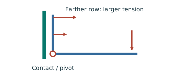
The load “peels” the bracket away, pivoting about the bottom bolt row. The top row is pulled hardest; every bolt shares the shear equally.
2023 PTE: , , ten M20 in two columns of five at . ; ; ; ✓. Solution
Concept map
Bracket bolts: why the top row is pulled hardest
A bracket sticks out from its support and the load tries to peel it off. The bolts do two jobs at once: all of them share the shear, and the upper rows also resist tension. The two routes meet in three checks — and the limit is 1.4, not 1.
- Cause
- Key idea
- Result
- What changes it
- How design deals with it
- Exam answer
- marks are often lost here
Text version (from cause to result)
Cause
, A load at distance e from the face
The load acts a distance out from the face where the bolts are.
Comes from (upstream)— (a starting point)
Leads to (downstream) The moment peels the bracket off Shear shared equally
Key idea
The moment peels the bracket off
The load times its lever arm gives a moment that tries to pull the top of the bracket away from the face.
Comes from (upstream), A load at distance e from the face
Leads to (downstream)It pivots about the bottom row Tension grows with distance: top row hardest
Key ideaWhere marks are lost
It pivots about the bottom row
The lecture assumes the bracket pivots about the bottom contact (bolt) line, so each row’s is measured from it; the bottom row has and no tension.
Comes from (upstream) The moment peels the bracket off
Leads to (downstream) How well the group resists peeling Tension grows with distance: top row hardest
What changes itWhere marks are lost
How well the group resists peeling
Bolts further from the pivot are more effective, measured by . With two identical columns of bolts, include both.
Comes from (upstream)It pivots about the bottom row
Leads to (downstream) Tension grows with distance: top row hardest
Result
Tension grows with distance: top row hardest
Each bolt’s tension is proportional to its distance from the pivot, so the top row () is pulled hardest.
Formula
Comes from (upstream) The moment peels the bracket offIt pivots about the bottom row How well the group resists peeling
Leads to (downstream)All three must hold; the limit is 1.4
Result
Shear shared equally
Every bolt shares the vertical shear equally — including the bottom row, which has no tension but still takes shear.
Formula
Comes from (upstream), A load at distance e from the face
Leads to (downstream)All three must hold; the limit is 1.4
What changes it
, Capacity of each bolt
Shear ; tension . M20 Grade 8.8: 91.875 kN and 109.76 kN.
Comes from (upstream)— (a starting point)
Leads to (downstream)All three must hold; the limit is 1.4
How design deals with itWhere marks are lost
All three must hold; the limit is 1.4
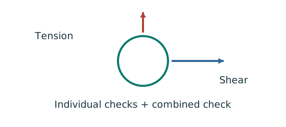
; ; . Check bearing too when the data allow.
Comes from (upstream) Tension grows with distance: top row hardest Shear shared equally, Capacity of each bolt
Leads to (downstream)Exam: all three conclusions
Exam answer
Exam: all three conclusions
2023 PTE: , , ✓. Solution
Comes from (upstream)All three must hold; the limit is 1.4
Leads to (downstream)— (the last step)
Tour steps
1. The load peels the bracket
The load sits from the face, giving a moment .
In this step, A load at distance e from the face The moment peels the bracket off
2. Pivot about the bottom row
is measured from the bottom row; measures how well the group resists.
In this stepIt pivots about the bottom row How well the group resists peeling
3. Two kinds of force
Tension comes from the moment and is largest at the top; shear is shared equally by all.
In this step Tension grows with distance: top row hardest Shear shared equally
4. Three checks
Shear and tension separately, then the interaction ≤ 1.4.
In this step, Capacity of each boltAll three must hold; the limit is 1.4Exam: all three conclusions
Welded double angles: two different weld lengths (2023 PTE)
The force in an angle acts through its centroid, which is closer to one edge. So the two side welds carry different shares: the weld nearer the centroid takes more. Share by the lever rule:
2023 PTE: 233 kN per angle, centroid 70.4 / 129.6 mm (leg 200): , ; with an 8 mm weld → effective lengths 107.8 / 58.6 mm. Solution
UB bracket welds: web takes shear, flanges take moment (2023 FT)
Split the work: the web welds carry the whole shear ; the two flange welds form a couple that carries the moment , so each flange force is with .
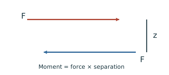
2023 FT: , , → ; the 8 mm flange weld (144 mm effective) carries 177.4 kN ✓; two 6 mm web welds (2 × 338 mm effective) carry 624.6 kN > 600 ✓. Note: Class 35 electrodes with S355 give . Solution
Bolt group with an in-plane eccentric load (older papers)
The same idea as the eccentric weld, with individual bolts instead of weld lines:
Where marks are usually lost Always examined
Next: try it yourself
- 2023 FT BQ2(a): double bolted angles (same type as 2024).
- 2022 BQ1(a): double-cover splice; 2022 BQ1(b): eccentric rectangular weld.
- 2023 PTE BQ2: welded angles and a bolted bracket.
- The reasons behind it: connections lecture.