Unrestrained beams (LTB): a table routine for each segment
The first 7 marks (reactions, shear and moment diagrams) use the same skills as the compulsory floor beams. The other 23 marks are one fixed “look-up routine”, repeated for each segment. Once the routine is smooth, this is the safest Section B question.
What is lateral-torsional buckling (LTB)? Always examined
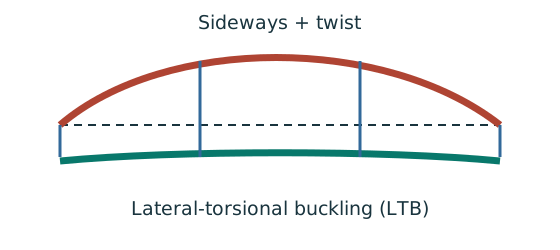
Concept map
Lateral-torsional buckling: why does a beam tip over sideways?
Understand the mechanism and the LTB calculation starts to make sense: every formula measures how easily the compression flange can escape sideways. The mechanism runs down the middle, with what makes it worse and how design responds.
- Cause
- Key idea
- Result
- What changes it
- How design deals with it
- Exam answer
- marks are often lost here
Text version (from cause to result)
Cause
The beam bends
In sagging the top flange is compressed and the bottom flange stretched; in hogging (e.g. a cantilever) the bottom flange is compressed.
Comes from (upstream)— (a starting point)
Leads to (downstream)The compression flange acts like a slender strut
Key idea
The compression flange acts like a slender strut
The compressed flange behaves like a slender strut that wants to bow sideways — about the weak axis of the section.
Comes from (upstream)The beam bends
Leads to (downstream)It bows sideways and twists
Key idea
It bows sideways and twists
The tension flange wants to stay straight while the compression flange moves sideways, so the whole section moves sideways and twists. That is lateral-torsional buckling.
Comes from (upstream)The compression flange acts like a slender strut
Leads to (downstream) Fails before the section is fully used
How design deals with itWhere marks are lost
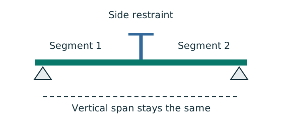
Lateral restraint (×): holds the compression flange at the side
Restraints split the beam into segments; shorter segments are safer. A restraint counts if it can resist 2.5% of the largest compression-flange force.
Comes from (upstream)— (a starting point)
Leads to (downstream) Longer unrestrained lengthA slab holds it all along → no LTB check
Result
Fails before the section is fully used
The beam fails sideways before reaching its section moment capacity , so it is checked against the smaller .
Comes from (upstream)It bows sideways and twists
Leads to (downstream) Restrained at a few points → check each segment
What changes it
Longer unrestrained length
The longer the flange is free between lateral restraints, the more easily it bows out. With normal loads is the segment length.
Comes from (upstream)Lateral restraint (×): holds the compression flange at the side
Leads to (downstream) Restrained at a few points → check each segment
What changes it
Weak-axis stockiness
The smaller (the narrower the flange), the easier it bows sideways. A narrow-flanged UB is more prone to LTB than a UC.
Comes from (upstream)— (a starting point)
Leads to (downstream) Restrained at a few points → check each segment
What changes it
Load on the top flange that moves with it
Once the beam twists, the load pushes it over further (destabilizing load), so . Exam questions usually state “normal load”.
Comes from (upstream)— (a starting point)
Leads to (downstream) Restrained at a few points → check each segment
What changes it
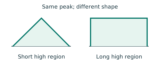
Shape of the moment diagram
A segment near the peak moment all along is most dangerous; a single peak is less so. turns an uneven moment into an equivalent uniform one.
Comes from (upstream)— (a starting point)
Leads to (downstream) Restrained at a few points → check each segment
How design deals with it
A slab holds it all along → no LTB check
A slab restrains the beam along its whole length (full lateral restraint), so the compulsory floor beams need no LTB check — but still need shear, bending and deflection.
Comes from (upstream)Lateral restraint (×): holds the compression flange at the side
Leads to (downstream)Exam: tell supports from restraints first
How design deals with it
Restrained at a few points → check each segment
All the factors above end up in one check: and → → → ; the moment shape → . Steps: LTB calculation map.
Comes from (upstream) Fails before the section is fully used Longer unrestrained length Weak-axis stockinessLoad on the top flange that moves with it Shape of the moment diagram
Leads to (downstream)Exam: tell supports from restraints first
Exam answer
Exam: tell supports from restraints first
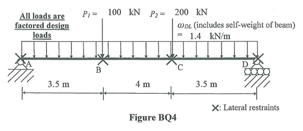
On the drawing: triangle / roller = support (reaction); cross × = lateral restraint (no reaction, only splits segments). “Fully restrained” means no LTB check.
Comes from (upstream)A slab holds it all along → no LTB check Restrained at a few points → check each segment
Leads to (downstream)— (the last step)
Tour steps
1. The compression flange is a strut
The beam bends → one flange is compressed → like a slender column it wants to bow sideways.
In this stepThe beam bendsThe compression flange acts like a slender strut
2. Sideways plus twist
The tension flange does not follow, so the section moves sideways and twists, failing before .
In this stepIt bows sideways and twists Fails before the section is fully used
3. What makes it worse?
A long unrestrained length, a slim weak axis, load on the top flange, and a segment near the peak moment all along.
In this step Weak-axis stockinessLoad on the top flange that moves with it Shape of the moment diagram
4. The remedy: lateral restraint
Hold the compression flange at the side to shorten the unrestrained length. A slab holding it all along → no LTB check.
In this stepLateral restraint (×): holds the compression flange at the side Longer unrestrained lengthA slab holds it all along → no LTB check
5. Everything ends in one check
Everything becomes , written once per segment.
In this step Restrained at a few points → check each segment
6. The first exam step
First separate supports from lateral restraints on the drawing — the most common mistake starts here.
In this stepExam: tell supports from restraints first
What does this question test? Always examined
| Part (2024) | Marks | What to do |
|---|---|---|
| (a) | 3 | support reactions |
| (b) | 4 | shear-force and bending-moment diagrams (with values) |
| (c) | 13 | LTB check of the first segment (BC) |
| (d) | 10 | LTB check of the second segment (CD) |
The method Always examined
Reactions (take moments)
Only points drawn with a support symbol have reactions; ignore the restraint crosses ×. The loads are usually already factored (the question says “factored”).
Shear-force and bending-moment diagrams
Work out the shear on both sides of each load and the moment at each load. Where the shear changes from positive to negative is the maximum moment. See core skills §3.
Design strength and class
from the flange thickness ; Class 1 or 2 → .
Effective length of each segment
Normally (normal load, restraints at both ends): segment length. If the load sits on the top flange and can move with it (destabilizing): ×1.2. Cantilever segments: use Table 8.1.
Slenderness
Look up and work out
Equivalent moment factor
If the moment diagram in the segment is curved (there is a UDL), use the quarter-point formula:
are the moments at ¼, ½ and ¾ of this segment; is the largest moment in the segment. If the diagram is a straight line you may use ( = ratio of the end moments).
Compare
Understanding map
LTB check: where every number comes from and where it goes
The hardest part of the LTB question is knowing which number goes into which formula. Read the map from top to bottom in answer order: numbers from the question and the tables at the top, the conclusion at the bottom. The values are from 2024 BQ4, segment BC (4 m).
- From the question
- From the tables
- Worked out
- Demand
- Capacity
- Check
- marks are often lost here
Text version (in working order)
From the questionWhere marks are lost
Segment length
Lateral restraints split the beam into segments, each checked on its own. Segment BC runs from B (3.5 m) to C (7.5 m).
Needs (upstream)— (a starting value)
Used for (downstream), , Quarter-point moments Largest moment in segment Effective length
From the questionWhere marks are lost
, Loads and supports
The design loads (already factored) and where the supports are. Only points drawn with a support symbol have reactions.
2024 BQ4 (segment BC)
Needs (upstream)— (a starting value)
Used for (downstream), Support reactions
From the tablesWhere marks are lost
Minor-axis radius of gyration
How “stocky” the section is about its weak axis. The larger it is, the harder it is to bow sideways.
Where it comes from: Section table (5.03 cm → 50.3 mm).
Needs (upstream)— (a starting value)
Used for (downstream) Slenderness
Worked out
Effective length
Normal load with restraints at both ends → segment length. Load on the top flange that can move sideways with it (destabilizing) → ×1.2. Cantilevers: Table 8.1.
Formula
2024 BQ4 (segment BC)
Needs (upstream) Segment length
Used for (downstream) Slenderness
Worked out
, Support reactions
Take moments about one support to find the other reaction; the two must add up to the total load.
Formula
2024 BQ4 (segment BC)
Needs (upstream), Loads and supports
Used for (downstream) Bending-moment diagram
From the tablesWhere marks are lost
Design strength
Look it up from the grade and the flange thickness . S355 with a flange thicker than 16 mm gives 345.
2024 BQ4 (segment BC)
Where it comes from: Data File design-strength table; from the section table. Core skills §5
Needs (upstream)— (a starting value)
Used for (downstream) Section factor Bending strength
From the tablesWhere marks are lost
Torsional index
A measure of how the section resists twisting; used only in the formula.
Where it comes from: Same section-table row.
Needs (upstream)— (a starting value)
Used for (downstream) Slenderness factor
Worked outWhere marks are lost
Slenderness
Length compared with stockiness. The larger it is, the more slender the segment and the easier it buckles.
Formula
2024 BQ4 (segment BC)
Needs (upstream) Effective length Minor-axis radius of gyration
Used for (downstream) Slenderness factor Equivalent slenderness
Worked out
Bending-moment diagram
Work out the shear and moment point by point from the reactions. Where the shear changes from positive to negative is the maximum moment.
Formula
2024 BQ4 (segment BC)
Where it comes from: Method: core skills §3.
Needs (upstream), Support reactions
Used for (downstream), , Quarter-point moments Largest moment in segment
Worked out
Section factor
Class 1 or 2 section → . Classification uses , which comes from .
Where it comes from: Section classification (core skills §6).
Needs (upstream) Design strength
Used for (downstream) Equivalent slenderness
From the tables
Buckling parameter
A section-shape factor, read straight from the table.
Where it comes from: Same section-table row.
Needs (upstream)— (a starting value)
Used for (downstream) Equivalent slenderness
Worked out
Slenderness factor
A correction for twisting of the section, set by ; always below 1.
Formula
2024 BQ4 (segment BC)
Needs (upstream) Slenderness Torsional index
Used for (downstream) Equivalent slenderness
Worked outWhere marks are lost
, , Quarter-point moments
The moments at ¼, ½ and ¾ of this segment. For BC that is 1, 2 and 3 m from B, i.e. 4.5, 5.5 and 6.5 m from A.
2024 BQ4 (segment BC)
Needs (upstream) Bending-moment diagram Segment length
Used for (downstream) Equivalent moment factor
Demand
Largest moment in segment
The largest moment (ignoring sign) inside this segment. For BC it is at C.
Needs (upstream) Bending-moment diagram Segment length
Used for (downstream) Equivalent moment factor Equivalent moment (demand)
Worked out
Equivalent slenderness
Slenderness that also accounts for the section shape (). This is the number used to look up .
Formula
2024 BQ4 (segment BC)
Needs (upstream) Buckling parameter Slenderness factor Slenderness Section factor
Used for (downstream) Bending strength
Worked out
Equivalent moment factor
Turns an uneven moment into an equivalent uniform one. Close to the peak all along → near 1; peak at one point only → smaller, but never below 0.44.
Formula
2024 BQ4 (segment BC)
Needs (upstream), , Quarter-point moments Largest moment in segment
Used for (downstream) Equivalent moment (demand)
From the tables
Plastic modulus
The modulus of the fully yielded section (cm³); it turns the strength into a moment.
Where it comes from: Section table, the 610×229×140 UB row.
Needs (upstream)— (a starting value)
Used for (downstream) Buckling resistance moment
Worked outWhere marks are lost
Bending strength
Interpolate in Table 8.3a, in the column, using . The larger (more slender), the smaller .
Formula
2024 BQ4 (segment BC)
Where it comes from: Data File p.5, Table 8.3a, column.
Needs (upstream) Equivalent slenderness Design strength
Used for (downstream) Buckling resistance moment
Demand
Equivalent moment (demand)
The moment this segment really has to carry; it is compared with at the end.
2024 BQ4 (segment BC)
Needs (upstream) Equivalent moment factor Largest moment in segment
Used for (downstream) Segment BC conclusion
Capacity
Buckling resistance moment
The largest moment this segment can carry before it buckles sideways.
Formula
2024 BQ4 (segment BC)
Needs (upstream) Bending strength Plastic modulus
Used for (downstream) Segment BC conclusion
Check
Segment BC conclusion
If the demand is not larger than the capacity, the segment passes. Write this conclusion for every segment.
2024 BQ4 (segment BC)
Needs (upstream) Equivalent moment (demand) Buckling resistance moment
Used for (downstream)— (the final conclusion)
Tour steps
1. Find the segment
Read the drawing: supports give reactions; restraint crosses (×) split the beam into segments. BC is 4 m long, and everything below is worked out for this segment only.
In this step, Loads and supports Segment length
2. Reactions and moment diagram (7 marks)
The same skill as the compulsory floor beams: take moments for the reactions, then work out shear and moment at each point and label them.
In this step, Support reactions Bending-moment diagram
3. The demand on this segment
Take the quarter-point moments and the maximum inside the segment, work out , then multiply by to get the demand, 558.1 kN·m.
In this step, , Quarter-point moments Largest moment in segment Equivalent moment factor Equivalent moment (demand)
4. One trip to the tables
Copy from the same section-table row; from ; Class 1 → .
In this step Design strength Section factor Plastic modulus Minor-axis radius of gyration Buckling parameter Torsional index
5. From length to slenderness
comes from the segment length; ; comes from .
In this step Effective length Slenderness Slenderness factor
6. Equivalent slenderness
— four arrows meet here, and this is the number for the table.
In this step Equivalent slenderness
7. Look up , work out
Interpolate in the 345 column of Table 8.3a, then multiply by to get the capacity .
In this step Bending strength Buckling resistance moment
8. Compare and conclude
558.1 < 973.4 → segment BC passes. Walk the same path again for CD (2024 answer: 365.8 < 1075.1 ✓).
In this step Segment BC conclusion
| Common cases (no intermediate restraint) | |
|---|---|
| simply supported segment, one central point load | 0.85 |
| simply supported segment, full-length UDL | 0.93 |
| straight-line diagram, zero at one end, maximum at the other () | 0.60 |
| cantilever segment (no intermediate restraint) | 1.00 |
Walkthrough: 2024 BQ4 (30 marks) Always examined
Given: an 11 m simply supported 610×229×140 UB, S355, Class 1. Design loads: 100 kN at B (3.5 m from A), 200 kN at C (7.5 m from A), and 1.4 kN/m over the whole span (self-weight included). Lateral restraints at A, B, C and D; only A and D are supports. All loads are already factored.
From the table: , , , , .
Past-paper walkthrough
(a) Reactions — 3 marks
Past-paper walkthrough
(b) Shear-force and bending-moment diagrams — 4 marks
| Position | Shear (left / right, kN) | Moment (kN·m) |
|---|---|---|
| A | 0 / +139.52 | 0 |
| B (3.5 m) | +134.62 / +34.62 | 479.74 |
| C (7.5 m) | +29.02 / −170.98 | 607.01 (max) |
| D (11 m) | −175.88 / 0 | 0 |
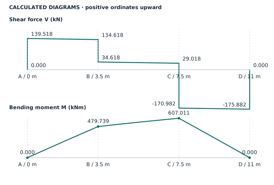
The shear changes sign at C → the maximum moment is at C.
Past-paper walkthrough
(c) Segment BC (4 m long) — 13 marks
Quarter points (4.5, 5.5, 6.5 m from A): , , , .
Past-paper walkthrough
(d) Segment CD (3.5 m long) — 10 marks
Quarter points (8.375, 9.25, 10.125 m): , , ; (at C).
Full solution with the drawn diagrams: 2024 BQ4.
How much does one extra restraint help? (2023 PTE) Often examined
A 6 m simply supported 406×140×46 UB with 110 kN at midspan. Same beam, different restraints:
| restraints at the ends only | plus a midspan restraint | |
|---|---|---|
| segment length | 6 m (one segment) | 3 m (two segments) |
| 0.85 (central point load) | 0.60 (straight line, ) | |
| demand | 140.3 kN·m | 99.0 kN·m |
| → | 140.1 → 79.9 | 80.4 → 188.8 |
| 70.9 kN·m → fails | 167.7 kN·m → passes |
Halving the segment more than doubles the resistance. That is why floor beams held by the slab (fully restrained) need no LTB check. Solution
Other versions Often examined
A beam with an overhang (2023 FT)
The supports are not at the beam ends; one end sticks out as a cantilever. Find the real supports from the support symbols; the reactions change. The cantilever moment is negative (top flange in tension, bottom flange in compression).
- Cantilever segment without intermediate restraint: .
- Its comes from lecture Table 8.1 (support and tip restraint conditions), not simply the segment length.
- Between the supports the moment may change from negative to positive; use the largest absolute value.
Destabilizing load
A load applied on the top flange that can move sideways with the beam (e.g. something resting directly on the flange) makes the twisting worse. Then use . Questions normally say “normal load”. Explanation
Where marks are usually lost Always examined
Next: try it yourself
- 2022 BQ3: two point loads, almost the same as 2024.
- 2023 PTE BQ4: the same beam with and without a midspan restraint.
- 2023 FT BQ4: with an overhang — harder.
- The reasons behind it: beams lecture sections 8–12.