Columns: classify → section check → two buckling formulas
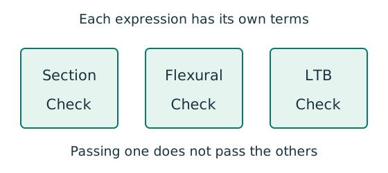
The column question has the most fixed procedure: classify, do one “section” formula, then two “buckling” formulas. Each formula adds up a few fractions; if the total is ≤ 1 it passes. The only difficulty is knowing which number goes where.
What does this question test? Always examined
| Part (2024) | Marks | What to do |
|---|---|---|
| (a) | 4 | section classification |
| (b) | 7 | cross-section capacity |
| (c) | 19 | member buckling: two interaction formulas |
Concept map
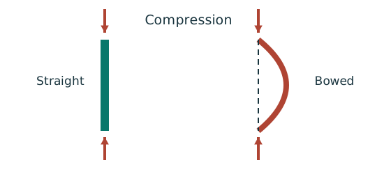
Column buckling: why a long column bows out before it crushes
The column question’s , , strut curves and all come from one idea: a column is never perfectly straight, and compression makes the bow grow. This map links those words.
- Cause
- Key idea
- Result
- What changes it
- How design deals with it
- Exam answer
- marks are often lost here
Text version (from cause to result)
What changes it
How the ends are held
Fixed ends make bowing harder than pinned ends. A pin symbol means free to rotate, not free to sway.
Comes from (upstream)— (a starting point)
Leads to (downstream) Effective length
How design deals with it
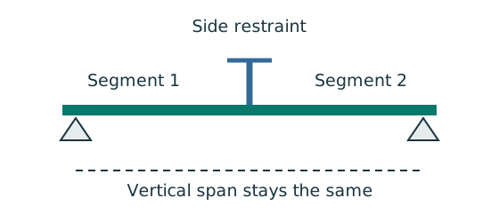
A tie in the weak direction
A tie at mid-height in the weak direction can halve the weak-axis effective length and raise the capacity without changing the section — but only in the direction it actually holds.
Comes from (upstream)— (a starting point)
Leads to (downstream) Effective length
Cause
Axial compression
The column carries the compression coming down from the floors above.
Comes from (upstream)— (a starting point)
Leads to (downstream)Compression makes the bow grow
Cause
No column is perfectly straight
Real columns have an initial bow. Design assumes it from (curve a₀) to (curve d), depending on the strut curve.
Source: Introduction lecture §14: imperfections
Comes from (upstream)— (a starting point)
Leads to (downstream)Compression makes the bow growSection shape → strut curve a/b/c/d
What changes itWhere marks are lost
Effective length
Turns the end conditions into an equivalent buckling length. For both ends fixed use the lecture’s recommended 0.7 (not the theoretical 0.5). If the question gives the effective length, use it.
Comes from (upstream)How the ends are heldA tie in the weak direction
Leads to (downstream) Slenderness: how slender it is
What changes it
Radius of gyration: how far the steel sits from the axis
The further the steel is spread from the axis, the larger and the harder it is to bow. Each section has two: a large and a small .
Comes from (upstream)— (a starting point)
Leads to (downstream) Slenderness: how slender it is
Key idea
Compression makes the bow grow
The compression acts through the bow and adds a moment that bends the column further — the member’s P–δ effect.
Source: P–Δ and P–δ concept map
Comes from (upstream) Axial compressionNo column is perfectly straight
Leads to (downstream) It buckles before it crushes
Key ideaWhere marks are lost
Slenderness: how slender it is
Combines length and stockiness into one number. The larger , the easier it buckles. Work it out for each axis separately.
Comes from (upstream) Effective length Radius of gyration: how far the steel sits from the axis
Leads to (downstream) It buckles before it crushes
Result
It buckles before it crushes
A long slim column fails sideways before the steel yields, so its design strength is below ; the more slender, the smaller . Only a short stocky column gets close to crushing ().
Comes from (upstream)Compression makes the bow grow Slenderness: how slender it is
Leads to (downstream) Read p_c, the weaker axis governs
What changes it
Section shape → strut curve a/b/c/d
Sections of different shape and thickness are more or less sensitive to imperfections, hence four curves. UC: b about , c about ; UB: a about , b about . The curve does not depend on the steel grade.
Comes from (upstream)No column is perfectly straight
Leads to (downstream) Read p_c, the weaker axis governs
How design deals with it
Read p_c, the weaker axis governs
Interpolate in Table 8.8 with , using the right curve and column, then multiply by the area for . Do both axes; the smaller governs. Worked numbers: column calculation map.
Comes from (upstream) It buckles before it crushesSection shape → strut curve a/b/c/d
Leads to (downstream)Exam: both axes, both curves
Exam answerWhere marks are lost
Exam: both axes, both curves
Write , which curve each uses, both interpolations and both — every line earns marks.
Comes from (upstream) Read p_c, the weaker axis governs
Leads to (downstream)— (the last step)
Tour steps
1. The cause: compression + not straight
A real column has an initial bow; the compression acts through it and makes the bow grow.
In this step Axial compressionNo column is perfectly straightCompression makes the bow grow
2. Length and stockiness
End conditions → effective length; how far the steel sits from the axis → ; together they give .
In this stepHow the ends are heldA tie in the weak direction Effective length Radius of gyration: how far the steel sits from the axis Slenderness: how slender it is
3. Buckling before crushing
That is why a long column’s design strength is below .
In this step It buckles before it crushes
4. Curves and the table
The section shape picks the curve; + curve + column → → .
In this stepSection shape → strut curve a/b/c/d Read p_c, the weaker axis governs
5. In the exam
Two axes, two curves, two values.
In this stepExam: both axes, both curves
Collect all the ingredients first Always examined
Find the UC row in Data File p.11 and copy:
| Symbol | Used for |
|---|---|
| → | design strength (S355 uses 345 if the flange is thicker than 16 mm) |
| classification | |
| (cm²) | and |
| (cm) | slenderness |
| (cm³) | moment capacities |
| for LTB |
The question usually gives: the design compression , the effective length , the top and bottom moments, the amplification factors, and a separately amplified .
The method Always examined
(a) Classify
. Flange → Class 1. The web is also compressed; the safest rule: if it is Class 1 whatever the axial force (a UC web has around 20, so it always passes).
Amplify the moments (once only)
The separately given is already amplified — do not multiply it again.
(b) Cross-section capacity: is one slice strong enough?
For a UC the minor axis is almost always limited by ; do not use alone.
Slenderness and compressive strength (both axes)
Section (thickness ≤ 40 mm) curve about curve about rolled H-section (UC) b c rolled I-section (UB) a b Interpolate in Table 8.8 using the right curve and the right column. Then and (with in cm², the answer is in kN). .
Moment factors (Table 8.9) and (Table 8.4a)
smaller end moment ÷ larger end moment. Single curvature (the column bends to one side) → positive; double curvature (S-shape) → negative.
(c-1) Interaction formula 1: compression buckling
Note: the denominators use the elastic (not ), even for a Class 1 section.
LTB bending resistance
Interpolate in Table 8.3a (Data File p.5) in the column.
(c-2) Interaction formula 2: compression + lateral-torsional buckling
Three small traps: the first term uses (minor axis); is the value given (already amplified); the last term uses the unamplified .
Understanding map
Columns: which number goes into which of the three formulas?
The column question always follows the same steps; the only difficulty is which number goes where, because the section formula and the two buckling formulas use different denominators. Tap any box to see which formula it ends up in. The values are from 2024 BQ3 (254×254×89 UC).
- From the question
- From the tables
- Worked out
- Demand
- Capacity
- Check
- marks are often lost here
Text version (in working order)
From the questionWhere marks are lost
Effective length
Given in the question (same for both axes). Used for the slenderness about each axis.
Needs (upstream)— (a starting value)
Used for (downstream), Slenderness, both axes
From the tables
, Radii of gyration
One for each axis (cm), giving two slendernesses. The minor-axis is much smaller.
Where it comes from: Section table (cm; ×10 for mm).
Needs (upstream)— (a starting value)
Used for (downstream), Slenderness, both axes
From the question
, End moments
The top and bottom moments about both axes, clockwise positive. They give the maximum moment and the sign of .
2024 BQ3
Needs (upstream)— (a starting value)
Used for (downstream), Amplified moments, End-moment ratios Formula 2: compression + LTB
From the tablesWhere marks are lost
Design strength
The flange is mm, thicker than 16 mm, so S355 gives 345. Nearly every capacity box uses it.
Where it comes from: from the section table (Data File p.11) → design-strength table.
Needs (upstream)— (a starting value)
Used for (downstream) (a) Section class Squash load, Section moment capacities, Compression resistance, Elastic moment capacities Buckling resistance moment
From the tables
, Buckling parameter, torsional index
Used only for the LTB , exactly as in the beam LTB question.
Where it comes from: Same section-table row.
Needs (upstream)— (a starting value)
Used for (downstream) Equivalent slenderness
Worked out
, Slenderness, both axes
Work out both. The minor-axis is usually larger, and it is also the for LTB.
Formula
2024 BQ3
Needs (upstream) Effective length, Radii of gyration
Used for (downstream), Compression resistance Equivalent slenderness
From the question
Amplification factor
Compression makes the column bend more, so the moments grow (P–δ). Amplify and once only.
Needs (upstream)— (a starting value)
Used for (downstream), Amplified moments
From the tables
Area
The area of the whole section. Used in and .
Where it comes from: Section table.
Needs (upstream)— (a starting value)
Used for (downstream) Squash load, Compression resistance
From the tables
, Elastic and plastic moduli
is the elastic and the plastic modulus (cm³), one pair per axis. The formulas use them differently: the section formula , the buckling formulas , and uses .
2024 BQ3
Needs (upstream)— (a starting value)
Used for (downstream), Section moment capacities, Elastic moment capacities Buckling resistance moment
Worked out
(a) Section class
. Flange and web → Class 1, so the plastic modulus may be used.
2024 BQ3
Needs (upstream) Design strength
Used for (downstream), Section moment capacities
Worked outWhere marks are lost
, End-moment ratios
Smaller end moment ÷ larger end moment. Single curvature (bending to one side) is positive; double curvature (S-shape) is negative.
2024 BQ3
Needs (upstream), End moments
Used for (downstream), , Moment factors
Worked out
Equivalent slenderness
As for beams: , from , .
Formula
2024 BQ3
Needs (upstream), Slenderness, both axes, Buckling parameter, torsional index
Used for (downstream) Buckling resistance moment
From the question
Design compression
The axial compression the column must carry (kN, factored). All three formulas start with it.
Needs (upstream)— (a starting value)
Used for (downstream) Cross-section capacity Formula 1: compression buckling Formula 2: compression + LTB
From the questionWhere marks are lost
Given M_LT
A separately given moment that is already amplified; used only in formula 2.
Needs (upstream)— (a starting value)
Used for (downstream) Formula 2: compression + LTB
Demand
, Amplified moments
The larger end moment on each axis times the factor. Used in the section formula and formula 1.
Formula
2024 BQ3
Needs (upstream), End moments Amplification factor
Used for (downstream) Cross-section capacity Formula 1: compression buckling
CapacityWhere marks are lost
Squash load
The force that yields the whole section; used only in the section formula.
Formula
2024 BQ3
Needs (upstream) Area Design strength
Used for (downstream) Cross-section capacity
CapacityWhere marks are lost
, Section moment capacities
Class 1 → may be used, capped at . Used only in the section formula.
Formula
2024 BQ3
Needs (upstream) Design strength, Elastic and plastic moduli (a) Section class
Used for (downstream) Cross-section capacity
CapacityWhere marks are lost
, Compression resistance
Interpolate in Table 8.8 with , using the right curve and column, then multiply by the area. UC: curve b about , curve c about .
Formula
2024 BQ3
Needs (upstream), Slenderness, both axes Design strength Area
Used for (downstream) Formula 1: compression buckling Formula 2: compression + LTB
Worked out
, , Moment factors
from Table 8.9; from Table 8.4a (with ), not below 0.44.
Formula
2024 BQ3
Needs (upstream), End-moment ratios
Used for (downstream) Formula 1: compression buckling Formula 2: compression + LTB
CapacityWhere marks are lost
, Elastic moment capacities
The buckling formulas use the elastic as the denominator, even for a Class 1 section.
2024 BQ3
Needs (upstream) Design strength, Elastic and plastic moduli
Used for (downstream) Formula 1: compression buckling Formula 2: compression + LTB
Capacity
Buckling resistance moment
Interpolate in the column of Table 8.3a and multiply by . Used only in formula 2.
Formula
2024 BQ3
Needs (upstream) Equivalent slenderness Design strength, Elastic and plastic moduli
Used for (downstream) Formula 2: compression + LTB
Check
Cross-section capacity
Is one “slice” strong enough? Three fractions added together must be ≤ 1.
Formula
2024 BQ3
Needs (upstream) Design compression Squash load, Amplified moments, Section moment capacities
Used for (downstream)— (the final conclusion)
Check
Formula 1: compression buckling
Will the whole column buckle in compression? Use the smaller of the two axes.
Formula
2024 BQ3
Needs (upstream) Design compression, Compression resistance, , Moment factors, Amplified moments, Elastic moment capacities
Used for (downstream)— (the final conclusion)
CheckWhere marks are lost
Formula 2: compression + LTB
The first term uses the minor-axis ; the middle term the given ; the last term the unamplified (65).
Formula
2024 BQ3
Needs (upstream) Design compression, Compression resistance, , Moment factors Given M_LT Buckling resistance moment, End moments, Elastic moment capacities
Used for (downstream)— (the final conclusion)
Tour steps
1. Collect the ingredients
Copy from the UC row on Data File p.11, and set from .
In this step Design strength Area, Radii of gyration, Elastic and plastic moduli, Buckling parameter, torsional index
2. (a) Classify (4 marks)
comes from ; Class 1 means the section formula may use the plastic modulus .
In this step (a) Section class
3. Amplify the moments (once only)
Take the larger end moment on each axis × 1.1. The separately given is already amplified — do not multiply again.
In this step, End moments Amplification factor, Amplified moments Given M_LT
4. (b) Section check (7 marks)
The denominators are and .
In this step Design compression Squash load, Section moment capacities Cross-section capacity
5. Slenderness and for both axes
; for a UC use curve b about and curve c about , in the 345 column. The minor axis usually governs.
In this step Effective length, Slenderness, both axes, Compression resistance
6. The sign of and the factors
Same sign at both ends → double curvature → negative . The factors follow from .
In this step, End-moment ratios, , Moment factors
7. (c-1) Formula 1
The denominators change to the elastic ; the first term uses the smaller .
In this step, Elastic moment capacities Formula 1: compression buckling
8. (as in the LTB question)
with gives ; look up and multiply by .
In this step Equivalent slenderness Buckling resistance moment
9. (c-2) Formula 2
Seven arrows meet here — watch the three small traps: , the given and the unamplified .
In this step Formula 2: compression + LTB
Concept map
C shape or S shape? The sign of and the moment factors and
Every year marks are lost on the sign of in the column question. Picture the shape the end moments bend the column into and the sign follows; then keep and apart — which table and which term.
- Cause
- Key idea
- Result
- What changes it
- How design deals with it
- Exam answer
- marks are often lost here
Text version (from cause to result)
Cause
, End moments at top and bottom
Exam papers usually give the applied top and bottom moments for each axis, clockwise positive.
Comes from (upstream)— (a starting point)
Leads to (downstream)Does the column bend into a C or an S? End-moment ratio and its sign
Key idea
Does the column bend into a C or an S?
Single curvature: the whole column bends to one side, like a C. Double curvature: there is a point of contraflexure in between, like an S.
Comes from (upstream), End moments at top and bottom
Leads to (downstream)An S shape is much less dangerous End-moment ratio and its sign
Result
An S shape is much less dangerous
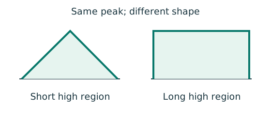
A C shape matches the shape the column buckles into, so it is the most dangerous; in an S shape the two halves bend opposite ways, so buckling is harder to trigger and the equivalent moment () is smaller.
Comes from (upstream)Does the column bend into a C or an S?
Leads to (downstream), Column buckling: Table 8.9 Lateral-torsional buckling: Table 8.4a
Key ideaWhere marks are lost
End-moment ratio and its sign
= smaller end moment ÷ larger end moment: positive for single curvature (C), negative for double curvature (S). With clockwise positive: same sign at both ends → double → negative; opposite signs → single → positive.
Comes from (upstream), End moments at top and bottomDoes the column bend into a C or an S?
Leads to (downstream), Column buckling: Table 8.9 Lateral-torsional buckling: Table 8.4a
How design deals with it
, Column buckling: Table 8.9
(); (). Each axis uses its own .
Comes from (upstream) End-moment ratio and its signAn S shape is much less dangerous
Leads to (downstream)The two tables are not interchangeableWhich term each one multiplies
How design deals with it
Lateral-torsional buckling: Table 8.4a
, using the major-axis .
Comes from (upstream) End-moment ratio and its signAn S shape is much less dangerous
Leads to (downstream)The two tables are not interchangeableWhich term each one multiplies
What changes it
The two tables are not interchangeable
Table 8.9 (column buckling) and Table 8.4 (LTB) differ most in double curvature, and their quarter-point formulas differ too. Decide which check it is first, then pick the table.
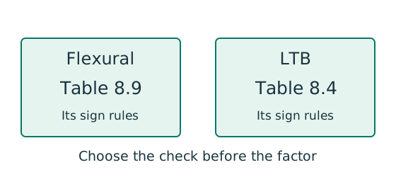
Comes from (upstream), Column buckling: Table 8.9 Lateral-torsional buckling: Table 8.4a
Leads to (downstream)Exam: give the reason for the sign
How design deals with itWhere marks are lost
Which term each one multiplies
Formula 1: and . Formula 2: and . The cross-section formula uses no .
Comes from (upstream), Column buckling: Table 8.9 Lateral-torsional buckling: Table 8.4a
Leads to (downstream)Simple construction: all equal 1Exam: give the reason for the sign
What changes it
Simple construction: all equal 1
For a column bent by eccentric beam reactions (simple construction), . See the simple-construction map.
Comes from (upstream)Which term each one multiplies
Leads to (downstream)— (the last step)
Exam answer
Exam: give the reason for the sign
For each axis: end moments → same or opposite sign → single or double → → . 2024: axis +75 / +45 → → ; axis +65 / −39 → → ; .
Comes from (upstream)Which term each one multipliesThe two tables are not interchangeable
Leads to (downstream)— (the last step)
Tour steps
1. The end moments decide the shape
First picture whether the column bends into a C or an S.
In this step, End moments at top and bottomDoes the column bend into a C or an S?
2. Why is an S safer?
A C matches the buckled shape; an S has halves bending opposite ways, so is smaller.
In this stepAn S shape is much less dangerous
3. The sign of
C is positive, S is negative. With clockwise positive, same sign = S = negative.
In this step End-moment ratio and its sign
4. Two tables
Column buckling uses Table 8.9 for ; LTB uses Table 8.4a for — not interchangeable.
In this step, Column buckling: Table 8.9 Lateral-torsional buckling: Table 8.4aThe two tables are not interchangeable
5. Where they go
appears only in the two buckling formulas; in simple construction they are all 1.
In this stepWhich term each one multipliesSimple construction: all equal 1
6. In the exam
For each axis write the reason: “same / opposite sign → single / double → ”.
In this stepExam: give the reason for the sign
Walkthrough: 2024 BQ3 (30 marks) Always examined
Given: 254×254×89 UC, S355, effective length 4 m, design compression 650 kN. Applied moments, clockwise positive: axis top +75, bottom +45 kN·m; axis top +65, bottom −39 kN·m. Amplification factor 1.1 for both axes; already-amplified .
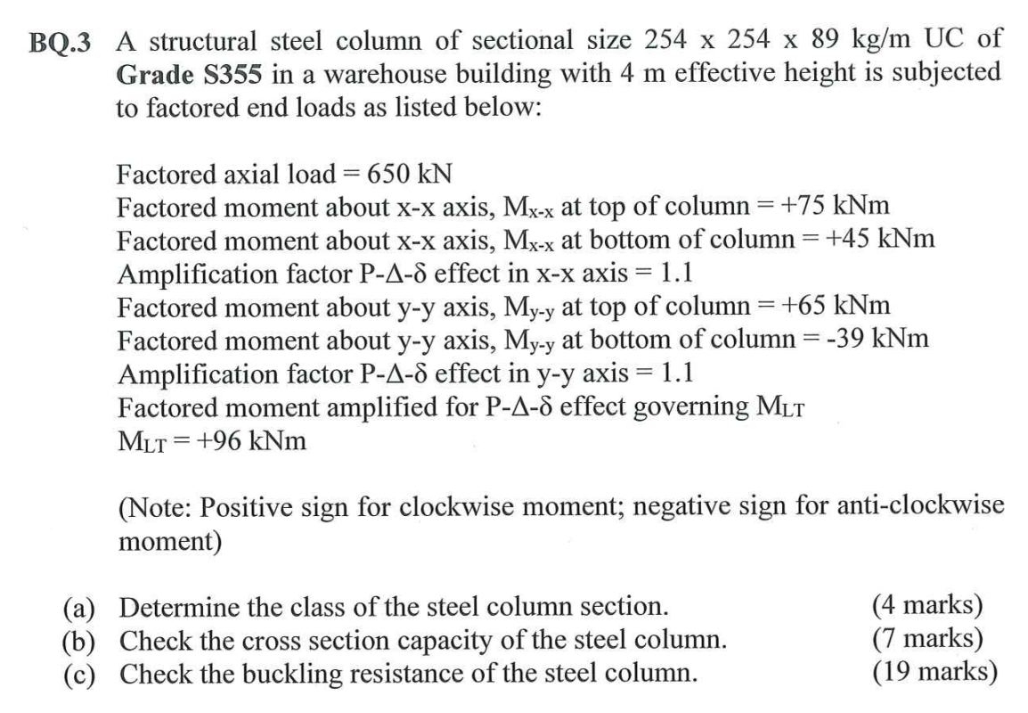
From the table (p.11): , , , , , , , , , , , .
Past-paper walkthrough
(a) Classification — 4 marks
Class 1.
Past-paper walkthrough
(b) Cross-section capacity — 7 marks
Past-paper walkthrough
(c) Member buckling — 19 marks
Moment factors: axis +75 / +45, same sign → double curvature, ; axis +65 / −39, opposite signs → single curvature, .
Compressive strength: UC → curve b about , curve c about , column.
Interaction formula 1 (elastic denominators , ):
LTB:
Interaction formula 2 (last term uses the unamplified ):
All three checks pass.
Full solution: 2024 BQ3.
The other version: simple construction (eccentric beam reactions) Often examined
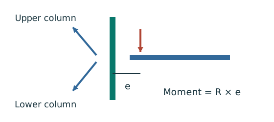
Eccentricity of each reaction
Beam on the column flange: ; beam on the column web: (use the question’s value if one is given).
Net moment
On the same axis, reactions from opposite sides partly cancel: (watch the directions).
Share the moment between upper and lower columns by stiffness
Accumulate the axial force
The lower column carries the reactions from all floors above plus this floor. Sharing the moment does not reduce the axial force.
Use the simplified formulas
For simple construction ; for LTB use ( = actual storey height, not the effective length). Compression still uses .
Concept map
Simple construction: the beams are pinned, so why is the column still bent?
“Pinned” makes it easy to think the column is only compressed. But the beam reaction is off the column centre, so it bends the column. The map splits two routes: the moment is shared by stiffness; the axial force accumulates floor by floor and is not shared.
- Cause
- Key idea
- Result
- How design deals with it
- Exam answer
- marks are often lost here
Text version (from cause to result)
Cause
Pinned beam-to-column joints
Simple design assumes pinned beam ends that pass no continuity moment; sideways loads go to bracing or a core.
Comes from (upstream)— (a starting point)
Leads to (downstream) The reaction is off-centre: eccentricity
Cause
Beams pass their reactions to the column
Each beam’s end reaction (factored) presses on the column.
Comes from (upstream)— (a starting point)
Leads to (downstream) The reaction is off-centre: eccentricity Axial force adds up floor by floor
Key idea
The reaction is off-centre: eccentricity
The reaction is taken 100 mm from the column face. Beam on the column flange: ; on the column web: (mm). Use the question’s value if given.
Comes from (upstream)Pinned beam-to-column jointsBeams pass their reactions to the column
Leads to (downstream) The column is bent
ResultWhere marks are lost
The column is bent
Reaction × eccentricity = moment. On the same axis, equal reactions from opposite sides cancel their moments.
Comes from (upstream) The reaction is off-centre: eccentricity
Leads to (downstream) Moment shared by stiffness
ResultWhere marks are lost
Axial force adds up floor by floor
The lower column carries the reactions of every floor above plus this floor. Only the moments cancel; the axial forces all add up.
Comes from (upstream)Beams pass their reactions to the column
Leads to (downstream)Simplified formulas: m = 1
How design deals with it
Simplified formulas: m = 1
In simple construction ; for LTB use with the actual storey height, not the effective length. Compression still uses .
Comes from (upstream) Moment shared by stiffness Axial force adds up floor by floor
Leads to (downstream)Exam answer order
Exam answer
Exam answer order
(1) for each reaction; (2) net moment ; (3) share by ; (4) accumulate the axial force; (5) use the formulas with . Example: 2023 FT BQ3.
Comes from (upstream)Simplified formulas: m = 1
Leads to (downstream)— (the last step)
Tour steps
1. Pinned, but the reaction is off-centre
A pin passes no moment, but the reaction acts a distance from the column centre.
In this stepPinned beam-to-column jointsBeams pass their reactions to the column The reaction is off-centre: eccentricity
2. So the column bends
; equal reactions on opposite sides cancel.
In this step The column is bent
3. Two routes, kept apart
The moment is shared between upper and lower columns by stiffness; the axial force just adds up.
In this step Moment shared by stiffness Axial force adds up floor by floor
4. Use the simplified formulas
, and LTB uses the actual storey height.
In this stepSimplified formulas: m = 1Exam answer order
Examples: 2023 FT BQ3, lecture examples 3 and 4.
Where marks are usually lost Always examined
Next: try it yourself
- 2023 PTE BQ3: the same format as 2024 (305×305×198 UC).
- 2022 BQ2: given moments and amplification factors again.
- 2023 FT BQ3: simple construction with eccentric reactions.
- The reasons behind it: columns lecture.