Connections: trace the force through bolts, plates and welds
Open “Animation lab” beside a teaching step for a visual explanation or a walkthrough of its original expressions. Models are illustrative; source answers remain unchanged.
Need a simpler picture? Open “Simple explanation” beside a difficult step. These optional notes do not replace the full solution.
A connection transfers force between pieces of steel. Identify what crosses the joint before counting bolts or measuring weld. A force acting along a member can produce bolt shear, plate tension and local bearing at the same time; all relevant resistances must be satisfactory.
Lecture examples are included immediately after the relevant concepts. Expand an example to read its complete diagram, working, exam answer and self-check here.
Bolts, grades and weld types
Source: Chapter 2 pp.2–3 and 6–7. An ordinary clearance bolt transfers load through contact between its shank and the hole after any clearance movement. A friction-grip connection uses clamping and friction; ordinary bearing-bolt equations alone are not an HSFG slip check. For the ordinary Grade 8.8 bolts used in the worked examples, the course tables give , and . Their nominal material ultimate tensile strength is a different quantity.
A grade label 8.8 indicates nominal ultimate strength and yield ratio , hence nominal yield strength in Chapter 2 Table 1. The code design strengths above are the values to use for capacity. Grade 4.6 has nominal yield/ultimate /; Grade 10.9 has /.
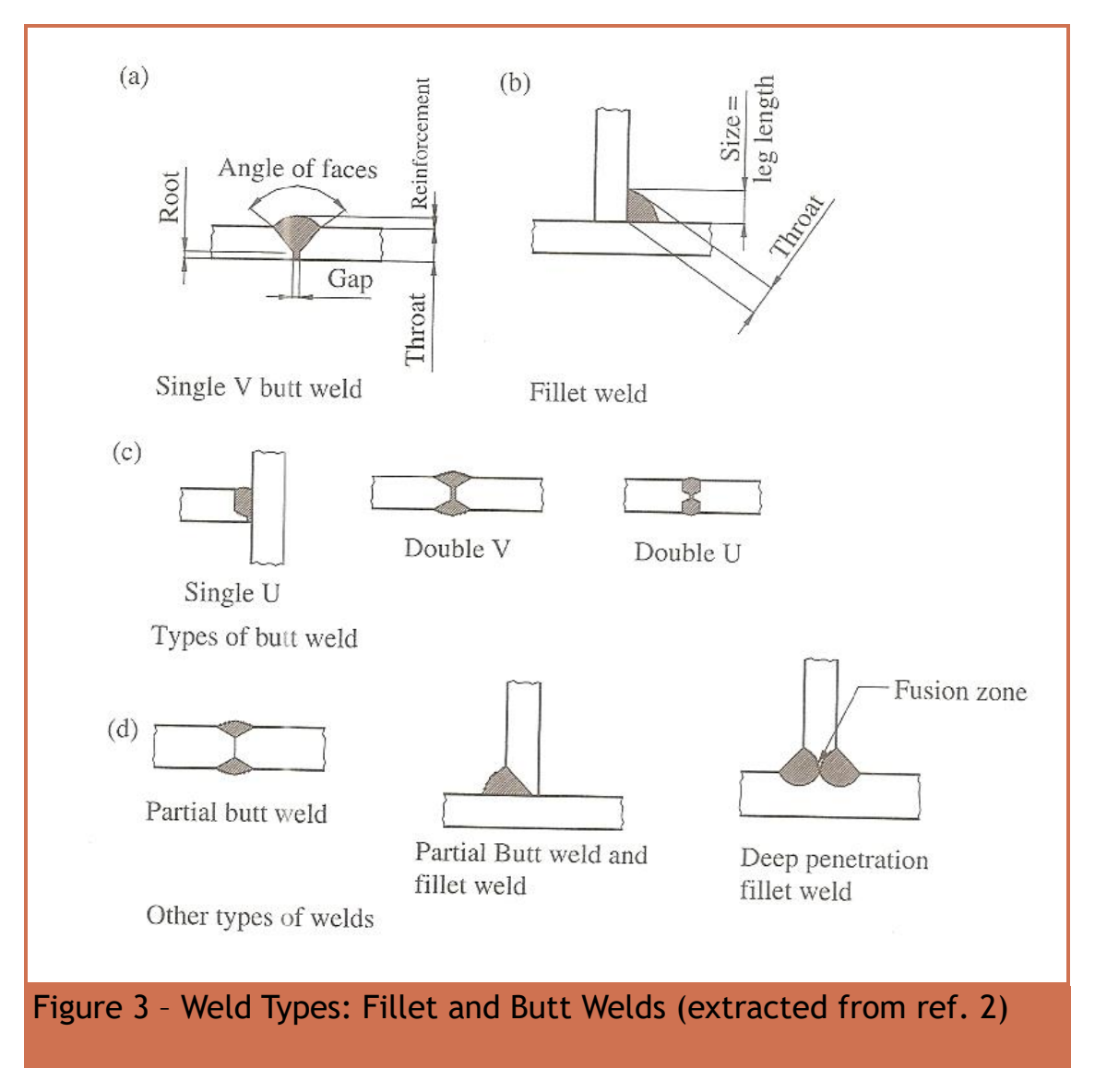
Fillet welds have a triangular profile; the specified size is the leg, not the throat. Butt welds join prepared plate edges, such as single/double V or U preparations. Visual inspection, dye penetrant and magnetic-particle methods look for surface issues; ultrasonic and X-ray methods can detect internal defects as described in the notes.
Animation labCount the bolt shear planes
Supplement to the original lesson. Enable JavaScript to play, step through calculations and rotate 3D models. The following explanation remains readable offline.
- Load must cross an interface between the connected plates.
- A lap joint gives one shear plane through a bolt.
- A symmetric double-cover joint may provide two shear planes. Count load-transfer interfaces, not just visible plates.
- Use the source’s area and shear strength. Then check bearing, plate resistance and detailing separately.
Hole size, pitch, gauge and edge distances
Simple explanation: The bolt can crush or tear the plate
A strong bolt can still push through a weak hole edge.
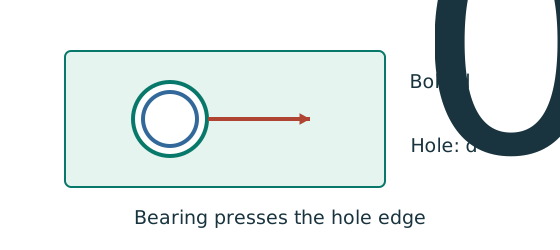
- Check the bolt and each connected plate’s bearing bounds.
- Use nominal bolt diameter for bearing; hole size for removed material.
- The smallest applicable resistance controls.
Remember: A short end distance may govern even when bolt shear passes.
Source: Chapter 2 pp.3–4. Nominal bolt diameter is the steel shank size. Hole diameter is larger: for , for larger ordinary bolts. Use for bearing area and spacing rules; for material removed by holes.
General minimum gauge transverse to the load: .
Maximum pitch/gauge: , where is the thinner connected-plate thickness.
Maximum edge distance: ; .
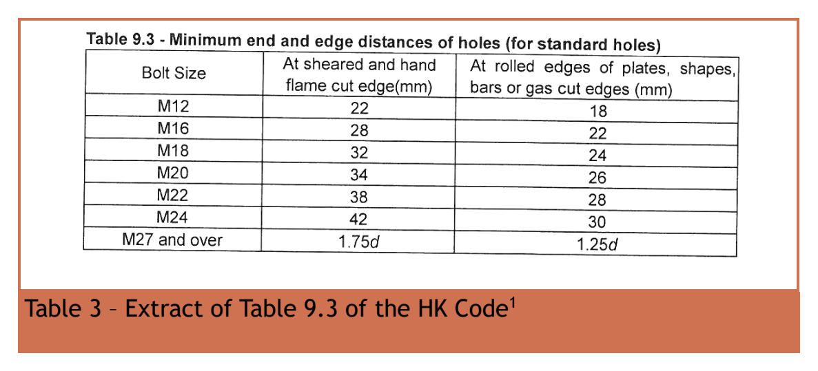
End distance is from the hole centre to the plate end in the load direction. Edge distance is from hole centre to an adjacent side edge. Minimum values depend on edge preparation. For M20, the supplied Table 9.3 gives at sheared/hand-flame-cut edges and at rolled, sawn or machine-cut edges. You cannot call a layout satisfactory without identifying the applicable edge type. Example 2 explicitly checks a rolled edge.
Animation labBolt centres, holes and edges
Supplement to the original lesson. Enable JavaScript to play, step through calculations and rotate 3D models. The following explanation remains readable offline.
- Hole diameter d₀ differs from nominal bolt diameter d. Net-section deductions use the specified hole.
- Pitch runs along the load direction; gauge measures spacing across rows.
- End and edge distances start at the hole centre. The remaining ligament starts at the hole boundary.
- Minimum spacing, edge distances, grip and plate thickness come from the specified rules, not this scaled illustration.
Recognise the competing failure modes
Source: Chapter 2 p.8. The bolt may shear across its cross section; bolt or plate may crush locally at the hole (bearing); the plate may tear across its net tensile section; a short plate end may tear out; or a block bounded by shear and tension paths may pull out. A larger bolt does not necessarily cure a weak net plate section, because its larger hole removes more material.
Use a load-path check: main plate → bolts or weld → cover/gusset → connected member. Resistances in series are compared using the minimum. Two identical cover plates sharing a load in parallel have capacities that can be added. The groups on opposite sides of a splice are in series: each side must transfer the whole splice force.
Animation labCount the bolt shear planes
Supplement to the original lesson. Enable JavaScript to play, step through calculations and rotate 3D models. The following explanation remains readable offline.
- Load must cross an interface between the connected plates.
- A lap joint gives one shear plane through a bolt.
- A symmetric double-cover joint may provide two shear planes. Count load-transfer interfaces, not just visible plates.
- Use the source’s area and shear strength. Then check bearing, plate resistance and detailing separately.
Shear planes and bolt shear capacity
Simple explanation: Count where the bolt can be sheared
The plate interfaces are the places trying to cut across the bolt.
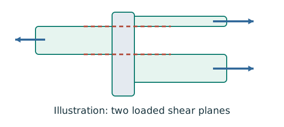
- Count actual loaded shear planes, not merely visible plates.
- Choose shank or threaded area for the plane concerned.
- Compare group resistance with the force that group transfers.
Remember: Bolts on opposite sides of a splice do not all act in parallel.
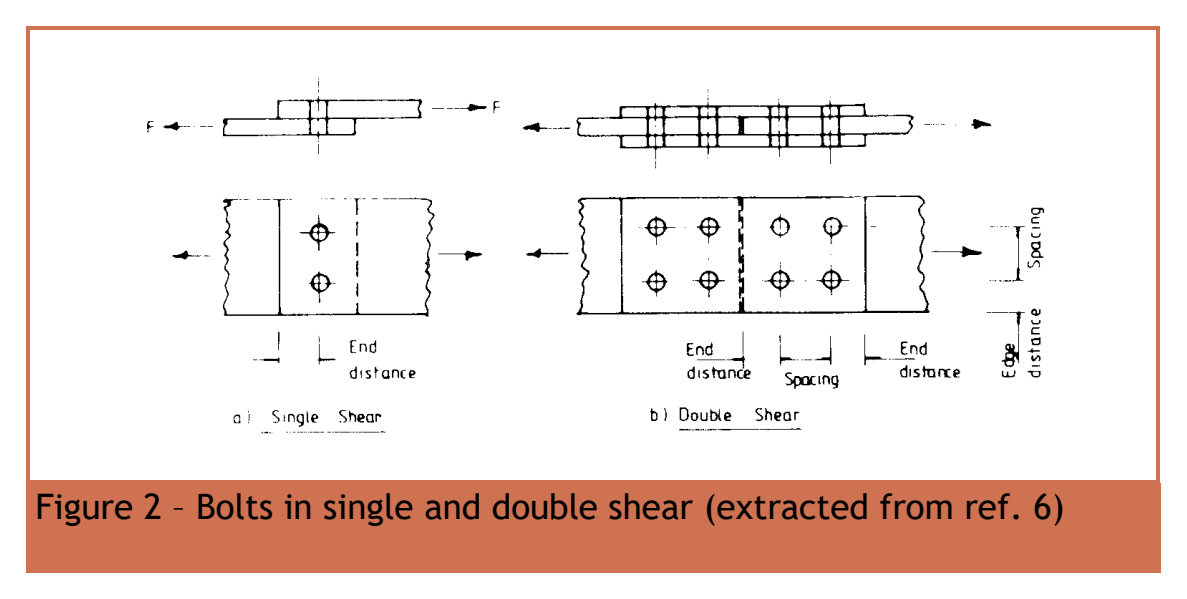
Use tensile stress area where the threads may lie in the shear plane. Use full shank area only when it is certain threads cannot be there. For M16/M20/M24/M30 the tensile stress areas are /// in the supplied table.
The “/” converts to : stress × area = . For a concentric group of equally loaded bolts, applied force per bolt is . For an eccentric group, use the maximum resultant force found from direct force plus moment; alone misses torsion.
Try it yourself. A Grade 8.8 M20 bolt has threads in two shear planes. Find its shear capacity.
Reveal answer and reasoning
. One-plane capacity is . Double shear is a geometry fact, not a property of Grade 8.8.
Animation labCount the bolt shear planes
Supplement to the original lesson. Enable JavaScript to play, step through calculations and rotate 3D models. The following explanation remains readable offline.
- Load must cross an interface between the connected plates.
- A lap joint gives one shear plane through a bolt.
- A symmetric double-cover joint may provide two shear planes. Count load-transfer interfaces, not just visible plates.
- Use the source’s area and shear strength. Then check bearing, plate resistance and detailing separately.
Animation labCount the bolt shear planes
Supplement to the original lesson. Enable JavaScript to play, step through calculations and rotate 3D models. The following explanation remains readable offline.
- Load must cross an interface between the connected plates.
- A lap joint gives one shear plane through a bolt.
- A symmetric double-cover joint may provide two shear planes. Count load-transfer interfaces, not just visible plates.
- Use the source’s area and shear strength. Then check bearing, plate resistance and detailing separately.
Bearing and end tear-out: calculate every bound
Simple explanation: The bolt can crush or tear the plate
A strong bolt can still push through a weak hole edge.
- Check the bolt and each connected plate’s bearing bounds.
- Use nominal bolt diameter for bearing; hole size for removed material.
- The smallest applicable resistance controls.
Remember: A short end distance may govern even when bolt shear passes.
Source: Chapter 2 pp.9–10. Bearing is local crushing where a bolt pushes on its hole. The projected bearing area is , not . For symmetric double-cover splices, compare the main thickness with the combined cover thickness to find the governing load path; alternatively check the main plate at full load and each cover at half load.
, , and are in . is end distance measured along load transfer. is the clear ligament between neighbouring hole edges in that direction: for aligned equal holes, pitch − . for standard holes, for oversize/short slots in this extract. For S355, and . For Grade 8.8, . This notation can look like in the source; it is a length, not a moment of inertia.
The first bound checks bearing strength, the second captures end-distance limitation, and the third includes a clear-ligament limit and an upper cap. Write all numbers before taking the minimum. Do not apply the largest result as capacity.
Animation labBearing and the remaining ligament
Supplement to the original lesson. Enable JavaScript to play, step through calculations and rotate 3D models. The following explanation remains readable offline.
- Force transfers through contact between bolt and connected plate.
- The plate around the hole carries bearing stress. Bolt bearing and plate bearing are separate checks.
- A short ligament can tear out towards the end. The direction of force determines the relevant edge.
- Evaluate every specified bearing and ligament bound for each layer and retain the smallest applicable resistance.
Tension and the prying assumption
Simple explanation: Why the top bolt row is pulled hardest
The bracket tries to peel away from the support about the assumed contact line.
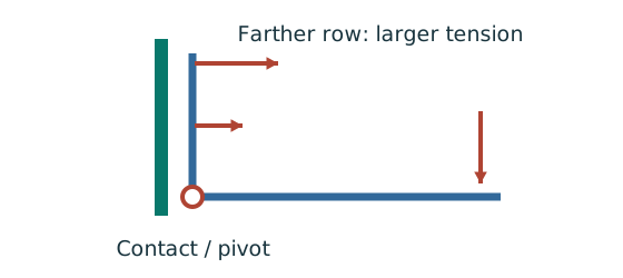
- Use the rotation/contact line assumed by the course model.
- Measure each bolt row’s distance from that line.
- Check maximum tension, direct shear and their interaction.
Remember: A row at the pivot can still carry direct shear.
Source: Chapter 2 pp.10–11. Bolt tension acts along the bolt axis, trying to separate connected surfaces. The direct tensile capacity is . For the course’s simplified treatment avoiding explicit prying-force design, use reduced nominal tension .
The source Clause 9.3.7.2 extract also restricts flange bolt gauge for UB/UC/T flange details. Reducing capacity by is not blanket proof that every flexible plate has no prying. Where the exercise uses the simplified bracket model but does not supply sufficient gauge/plate details, state that model’s applicability and avoid claiming the whole joint has been comprehensively designed.
Animation labOut-of-plane bolt tension and prying
Supplement to the original lesson. Enable JavaScript to play, step through calculations and rotate 3D models. The following explanation remains readable offline.
- A bracket moment can create compression at the plate contact and tension in the bolt rows.
- The original assumed pivot/compression line determines each row distance.
- Under the elastic row model, a farther tension row attracts more tension. Direct shear may act simultaneously.
- Flexible plates can add prying force. Use nominal tension and interaction rules exactly as specified by the course.
Gross, net and effective area
Simple explanation: Why holes reduce tension resistance
The pull must squeeze through the steel left beside the holes.
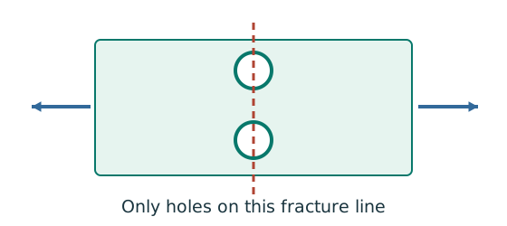
- Choose a possible fracture line across the member.
- Subtract the holes crossed by that line using hole diameter.
- Apply the course effective-area rule and its gross-area limit.
Remember: Do not subtract every hole anywhere in the connection.
Source: Chapter 2 pp.11–12. Gross area includes the original steel. Net area subtracts hole area along a possible fracture line normal to force. Effective tension area applies the course net-area coefficient but cannot exceed the corresponding gross area.
Here is the number of holes crossed by the fracture line, not the total bolts along the connection. In a two-row splice, a straight transverse section crosses two holes even when many bolts lie along the length.
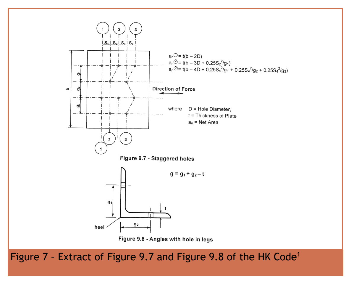
① ;
② ;
③ .
Figure 9.8: heel means the angle root. The developed gauge across the two legs is . All dimensions follow their source locations; do not estimate values from drawing scale.Open full-size image
For staggered holes, compare all credible straight and zigzag net areas. For each diagonal step, the deduction is reduced by , where is longitudinal stagger and transverse gauge. Thus . Select the smallest net area, equivalent to the largest deduction. For bolts on both angle legs, use the developed gauge shown in the source. This course supplies the geometric rule, not a numbered staggered calculation.
For shear area, the notes permit ignoring holes only if . Otherwise the stated net shear capacity is . This is distinct from the ordinary gross rolled-beam shear formula.
Connection example 2: design a bolted tension splice
Open this example on its own page
Design a double-cover splice for an already ultimate tensile force of . Main plates are wide × thick; two S355 cover plates are thick. Use Grade 8.8 M20 bolts in holes, pitch and end distance.
Original source: LectureNotes/Ch 2_Connection.pdf — p. 18, p. 19, p. 20. Values tagged given are in the question or diagram; lookup values come from a named table; calculated values follow from the working; assumptions are stated explicitly.
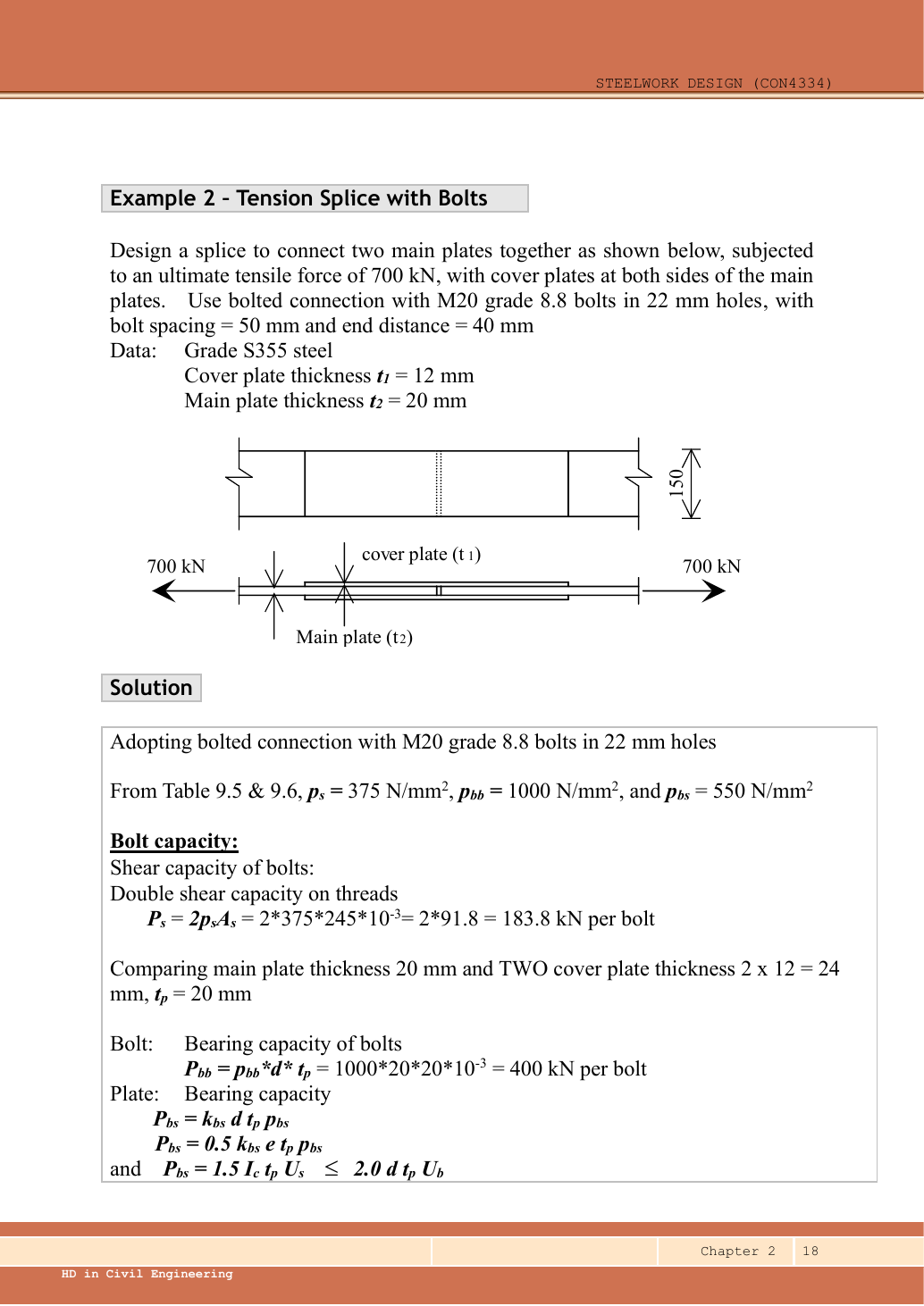
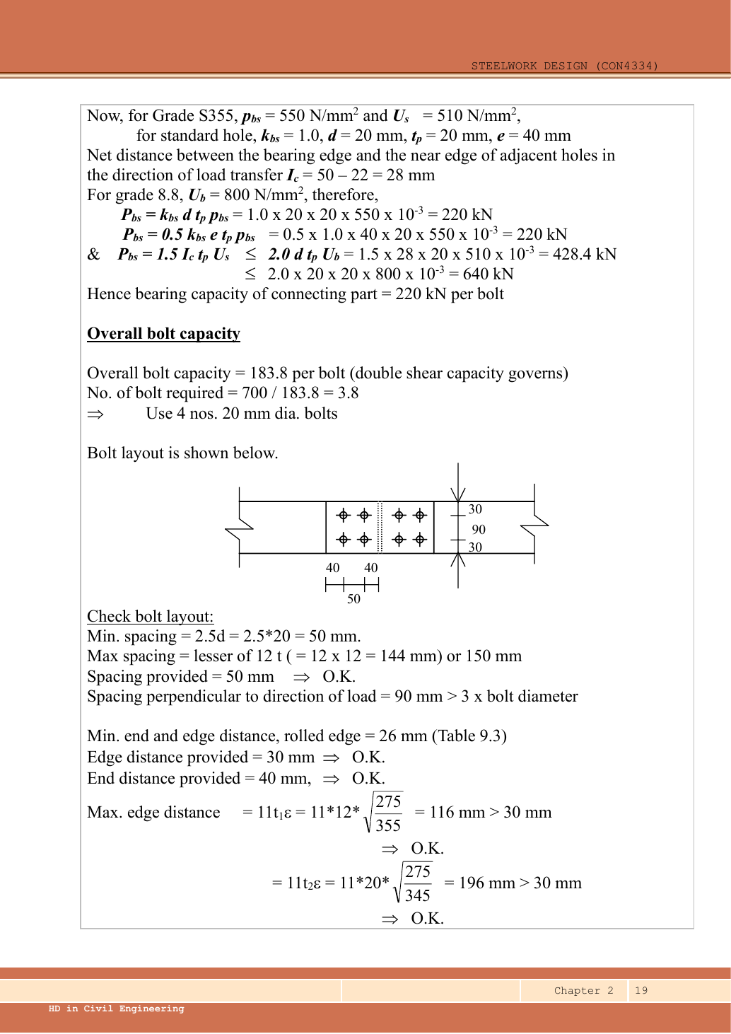
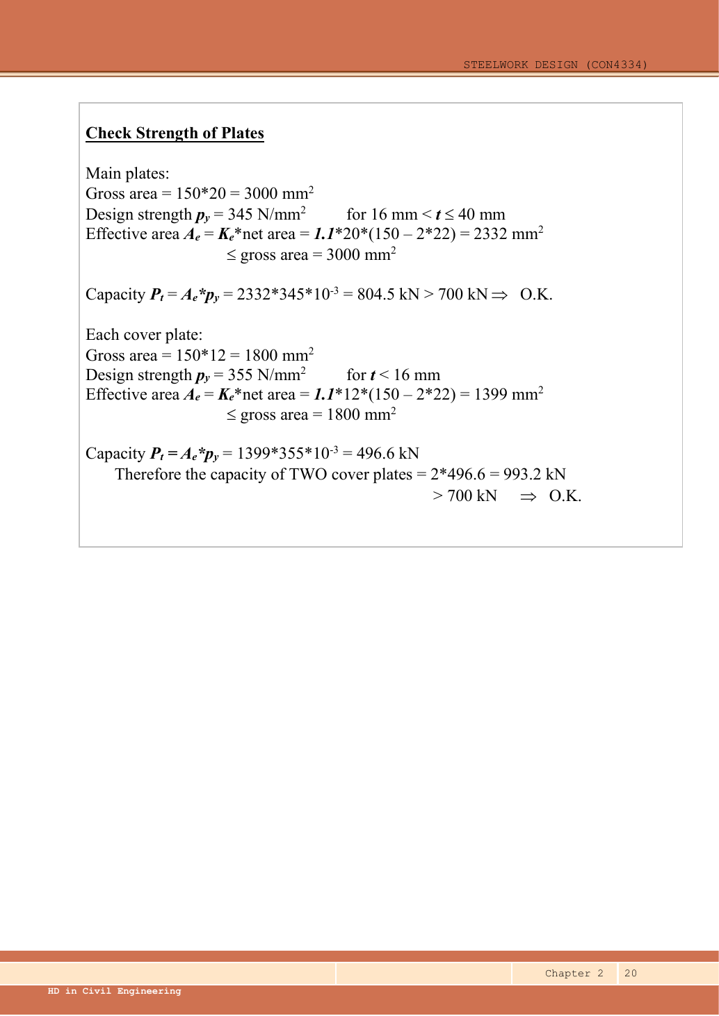
Read the diagram and collect the data
| Input | Origin |
|---|---|
| Given demand | ultimate; no further factor. |
| Given thicknesses | Main ; each cover ; cross-section view labels each ply. |
| Given hole/pitch/end | M20 → ; stated hole ; longitudinal pitch ; end . |
| Selected layout | p.19 drawing: two rows, gauge , side edges , two columns per half-splice. |
| Lookup | , , ; S355 , , . Main for ; covers for . All stress units . |
Before calculating: recognition and strategy
Each half-splice must transfer the full from a main plate into the covers. The covers each take half that force. Bolts have two shear planes; compare main thickness with total cover thickness for the bearing path. Select bolt count from the weakest per-bolt mode, round up, arrange the bolts, then check the plates cut by those holes.
1. Establish the capacity of one bolt and its bearing path
Simple explanation: Count where the bolt can be sheared
The plate interfaces are the places trying to cut across the bolt.
- Count actual loaded shear planes, not merely visible plates.
- Choose shank or threaded area for the plane concerned.
- Compare group resistance with the force that group transfers.
Remember: Bolts on opposite sides of a splice do not all act in parallel.
Using total cover thickness is valid here because the two identical covers share the force symmetrically. An unequal cover arrangement would need separate load-sharing checks.
Animation labCount the bolt shear planes
Supplement to the original lesson. Enable JavaScript to play, step through calculations and rotate 3D models. The following explanation remains readable offline.
- Load must cross an interface between the connected plates.
- A lap joint gives one shear plane through a bolt.
- A symmetric double-cover joint may provide two shear planes. Count load-transfer interfaces, not just visible plates.
- Use the source’s area and shear strength. Then check bearing, plate resistance and detailing separately.
2. Select bolts on each side of the splice
Provide four on the left and four on the right: eight physical bolts in total. The eight do not jointly give “” across the splice, because the left and right groups carry the same force in series.
Animation labCount the bolt shear planes
Supplement to the original lesson. Enable JavaScript to play, step through calculations and rotate 3D models. The following explanation remains readable offline.
- Load must cross an interface between the connected plates.
- A lap joint gives one shear plane through a bolt.
- A symmetric double-cover joint may provide two shear planes. Count load-transfer interfaces, not just visible plates.
- Use the source’s area and shear strength. Then check bearing, plate resistance and detailing separately.
3. Verify the selected layout
The two transverse rows are separated by . Width closure:. Longitudinal pitch and end are the specified values. Use the source’s rolled-edge condition in Table 9.3, M20 row: minimum .
Animation labBolt centres, holes and edges
Supplement to the original lesson. Enable JavaScript to play, step through calculations and rotate 3D models. The following explanation remains readable offline.
- Hole diameter d₀ differs from nominal bolt diameter d. Net-section deductions use the specified hole.
- Pitch runs along the load direction; gauge measures spacing across rows.
- End and edge distances start at the hole centre. The remaining ligament starts at the hole boundary.
- Minimum spacing, edge distances, grip and plate thickness come from the specified rules, not this scaled illustration.
4. Check main-plate tension across two holes
Simple explanation: Why holes reduce tension resistance
The pull must squeeze through the steel left beside the holes.
- Choose a possible fracture line across the member.
- Subtract the holes crossed by that line using hole diameter.
- Apply the course effective-area rule and its gross-area limit.
Remember: Do not subtract every hole anywhere in the connection.
The critical straight transverse line crosses one hole in each row: two holes. Do not deduct all four holes along a half-splice. Thickness selects .
Animation labSubtract holes on the failure path
Supplement to the original lesson. Enable JavaScript to play, step through calculations and rotate 3D models. The following explanation remains readable offline.
- Gross area counts the complete plate width and thickness.
- The highlighted transverse path passes through the bolt holes.
- For the straight illustrative path, . Staggered paths require their specified correction.
- Net area is not always effective area. Include the course’s strength ratio or shear-lag rule when applicable.
5. Check both covers and conclude
All requested checks pass under the stated rolled-edge layout. The least load-path resistance is bolt shear . The source gives approximately for covers after intermediate rounding; carrying full precision gives .
Animation labSubtract holes on the failure path
Supplement to the original lesson. Enable JavaScript to play, step through calculations and rotate 3D models. The following explanation remains readable offline.
- Gross area counts the complete plate width and thickness.
- The highlighted transverse path passes through the bolt holes.
- For the straight illustrative path, . Staggered paths require their specified correction.
- Net area is not always effective area. Include the course’s strength ratio or shear-lag rule when applicable.
Compact exam answer
Four M20 Grade 8.8 bolts per side (eight total), two rows with gauge, pitch, ends and rolled edges. Double-shear resistance per half; bearing exceeds this. Main tension ; combined cover tension . Each exceeds . Layout passes for the source’s rolled-edge assumption.
Mistakes to avoid
- Do not factor the already ultimate .
- Four bolts are required on each side of the plate butt.
- Double shear doubles bolt shear, not the main-plate thickness.
- A transverse net section crosses two holes, not four.
Procedure for an unfamiliar variant
- Trace one half-splice at full force and each cover at its share.
- Calculate per-bolt shear/bearing and take the minimum.
- Round up bolt count and draw a feasible layout.
- Check every pitch/edge rule using the thinner ply and correct edge finish.
- Check main and cover effective tension areas independently.
Independent self-check
Try it yourself. If the required ultimate force becomes but the splice is unchanged, which calculated resistance fails first?
Hint
Compare with the complete group resistance, not just one bolt.
Reveal answer and reasoning
Bolt shear is inadequate. Main-plate tension and cover-pair tension still exceed . Adding bolts changes the layout and may change the fracture path, so repeat layout/net-area checks.
Animation labSubtract holes on the failure path
Supplement to the original lesson. Enable JavaScript to play, step through calculations and rotate 3D models. The following explanation remains readable offline.
- Gross area counts the complete plate width and thickness.
- The highlighted transverse path passes through the bolt holes.
- For the straight illustrative path, . Staggered paths require their specified correction.
- Net area is not always effective area. Include the course’s strength ratio or shear-lag rule when applicable.
Block shear
Simple explanation: A whole block can pull out
Think of tearing a small tab out of a sheet along several connected edges.
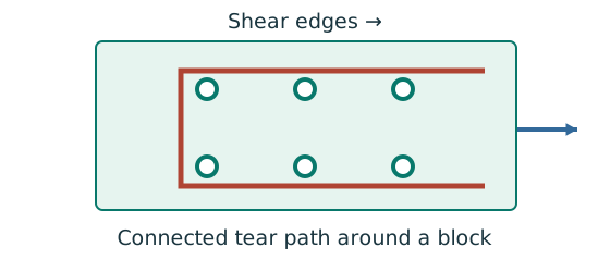
- Trace the complete block around the bolt group.
- Separate edges sliding in shear from the edge pulled in tension.
- Deduct holes only where the applicable path crosses them.
Remember: One straight net-section check does not cover block shear.

Read along the prospective shear face and across the tensile face, as labelled on the original detail. The source’s effective-area expression is , followed by . is the tensile-face hole diameter; for slots use the dimension normal to load. The extract gives for a single bolt row or for two rows. Match the illustrated path; do not substitute the whole plate length or an arbitrary bolt-group perimeter. No numerical block-shear example with all path dimensions is supplied.
Animation labSeparate the block-shear paths
Supplement to the original lesson. Enable JavaScript to play, step through calculations and rotate 3D models. The following explanation remains readable offline.
- A block containing the connection can detach from the surrounding plate.
- The paths parallel to the applied force carry shear.
- The closing path across the end of the block carries tension.
- Use the specified gross/net deductions and resistance expression. This is different from a single straight net-section fracture.
Single and double angles connected through one leg
Simple explanation: One connected leg does not load both legs equally
The connected leg receives the pull first; the other leg receives it through the angle.
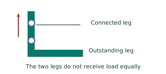
- Identify connected and outstanding legs from the drawing.
- Use the relevant bolted or welded angle rule.
- Keep the lecturer’s area convention consistent.
Remember: Bolted and welded reduction expressions are not the same rule.
Source: Chapter 2 pp.14–15. The unconnected leg does not receive the load directly, so the effective tension resistance is reduced. Let be the gross area of the unconnected leg and the sum of effective leg areas. Avoid counting the heel overlap twice: the lecture’s rectangular approximation allocates half the thickness to each leg.
| Connection | Capacity |
|---|---|
| Single angle, bolted | |
| Single angle, welded | |
| Double angles on both sides of gusset, interconnected, bolted | |
| Same double-angle arrangement, welded |
Use either total areas for the pair or calculate one identical angle at half load and double its capacity. Do not use total area and then double the answer again. For tension members with separately applied moments the notes give . Nominal connection eccentricity for the listed single-leg shapes is already allowed for by the specific reduction; do not invent an extra moment without a task requirement.
Connection example 1: single bolted unequal angle
Open this example on its own page
Check a single S355 angle connected through its long leg to a plate by the stated two Grade 8.8 M20 bolts. Dead tension is ; imposed tension is . Check bolt shear, bolt/plate bearing and angle tension.
Original source: LectureNotes/Ch 2_Connection.pdf — p. 16, p. 17. Values tagged given are in the question or diagram; lookup values come from a named table; calculated values follow from the working; assumptions are stated explicitly.
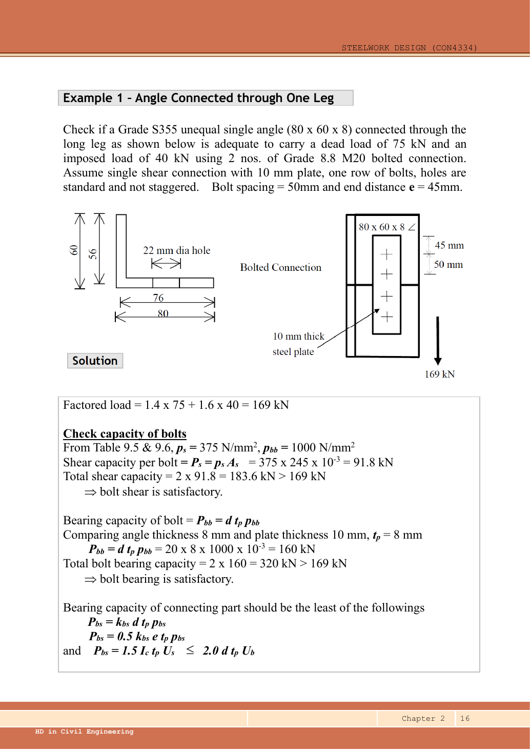
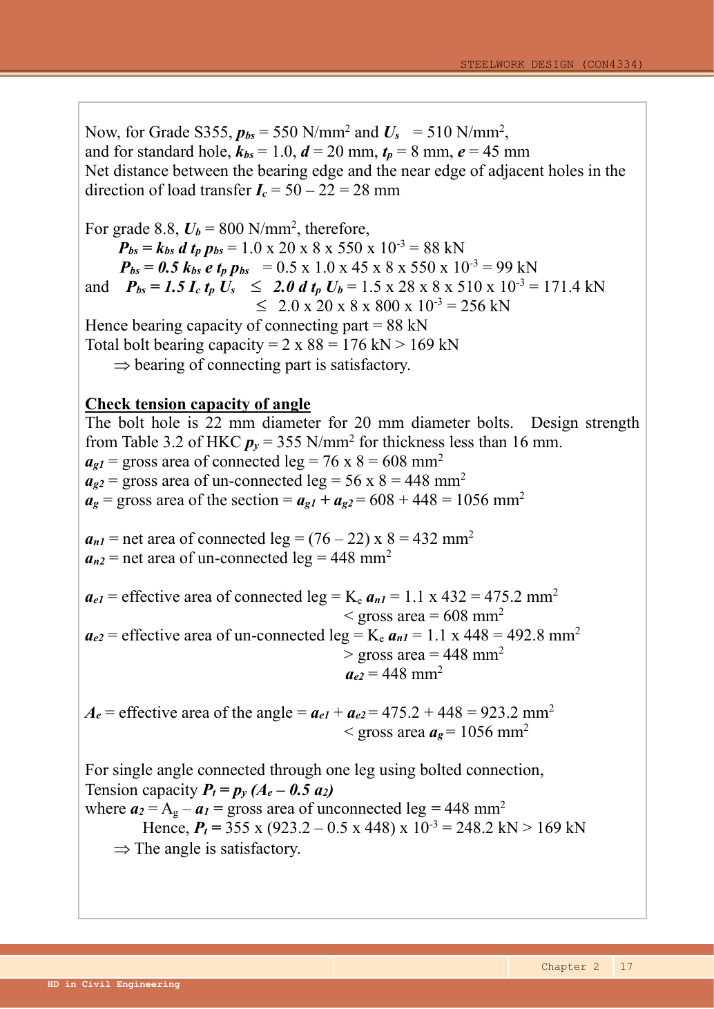
Read the diagram and collect the data
| Input | Value and exact source |
|---|---|
| Given loads | dead and imposed, question text; the downward arrow is the resulting tension direction. |
| Given geometry | Long leg ; short leg ; . The split dimensions and allocate half the heel thickness to each leg. |
| Given fasteners | Text specifies TWO M20 Grade 8.8 bolts; standard holes; pitch; end distance. |
| Given plate/model | supporting plate; one shear plane explicitly stated. |
| Lookup | Ch 2 p.3 M20 tensile stress area . Ch 2 pp.9–10 Grade 8.8: , , . S355: , , . Data File p.1, thickness : . |
Before calculating: recognition and strategy
This is concentric tension through one connected angle leg. The load crosses the angle-to-plate interface as bolt shear, presses on holes as bearing, and remains tension in the angle. Start with the factored force. Check each fastener mode, then the reduced angle tension resistance. Prerequisites: stress×area gives force; “net area” removes holes; a single-leg connection needs the specific unconnected-leg reduction.
1. Convert characteristic loads to one design force
is the ULS tensile demand in . Apply the course gravity factors once; the supplied loads are characteristic, not already ultimate.
Animation labFrom characteristic to design load
Supplement to the original lesson. Enable JavaScript to play, step through calculations and rotate 3D models. The following explanation remains readable offline.
- G is permanent load; Q is imposed load. A surface load and a line load also have different units.
- This illustration uses the course gravity case . Other combinations in the original text retain their own factors.
- For illustrative , change Q and watch each separate contribution.
- Do not carry this ULS total automatically into deflection. Follow the stated SLS load case.
2. Bolt shear across the single interface
Simple explanation: Count where the bolt can be sheared
The plate interfaces are the places trying to cut across the bolt.
- Count actual loaded shear planes, not merely visible plates.
- Choose shank or threaded area for the plane concerned.
- Compare group resistance with the force that group transfers.
Remember: Bolts on opposite sides of a splice do not all act in parallel.
is the tensile stress area because no thread-free shear plane is guaranteed. There is one interface between the angle leg and the support plate, so no factor for double shear.
Animation labCount the bolt shear planes
Supplement to the original lesson. Enable JavaScript to play, step through calculations and rotate 3D models. The following explanation remains readable offline.
- Load must cross an interface between the connected plates.
- A lap joint gives one shear plane through a bolt.
- A symmetric double-cover joint may provide two shear planes. Count load-transfer interfaces, not just visible plates.
- Use the source’s area and shear strength. Then check bearing, plate resistance and detailing separately.
3. Bearing of the bolts
Simple explanation: The bolt can crush or tear the plate
A strong bolt can still push through a weak hole edge.
- Check the bolt and each connected plate’s bearing bounds.
- Use nominal bolt diameter for bearing; hole size for removed material.
- The smallest applicable resistance controls.
Remember: A short end distance may govern even when bolt shear passes.
Use the thinner connected thickness : the angle leg governs. is the bolt diameter, not the hole.
Animation labBearing and the remaining ligament
Supplement to the original lesson. Enable JavaScript to play, step through calculations and rotate 3D models. The following explanation remains readable offline.
- Force transfers through contact between bolt and connected plate.
- The plate around the hole carries bearing stress. Bolt bearing and plate bearing are separate checks.
- A short ligament can tear out towards the end. The direction of force determines the relevant edge.
- Evaluate every specified bearing and ligament bound for each layer and retain the smallest applicable resistance.
4. Bearing and ligament resistance of the angle leg
The dimension is centre-to-centre pitch along tension. Subtract one full hole diameter to get the clear inter-hole ligament . The dimension is end distance from end to nearest bolt centre.
Plate bearing is closer to its limit than bolt shear: utilisation. This is why the larger bolt-bearing value cannot be used as the joint’s governing resistance.
Animation labBearing and the remaining ligament
Supplement to the original lesson. Enable JavaScript to play, step through calculations and rotate 3D models. The following explanation remains readable offline.
- Force transfers through contact between bolt and connected plate.
- The plate around the hole carries bearing stress. Bolt bearing and plate bearing are separate checks.
- A short ligament can tear out towards the end. The direction of force determines the relevant edge.
- Evaluate every specified bearing and ligament bound for each layer and retain the smallest applicable resistance.
5. Effective angle area and single-leg reduction
Simple explanation: One connected leg does not load both legs equally
The connected leg receives the pull first; the other leg receives it through the angle.
- Identify connected and outstanding legs from the drawing.
- Use the relevant bolted or welded angle rule.
- Keep the lecturer’s area convention consistent.
Remember: Bolted and welded reduction expressions are not the same rule.
Use the lecturer’s rectangular leg-area approximation. The heel is shared: connected leg width ; unconnected width . A transverse fracture line crosses one hole, not both bolts arranged along the member. Apply separately to each leg and cap each at its own gross area.
The factor belongs specifically to a single bolted angle connected through one leg (Ch 2 p.14). It is not a generic reduction for all tension members.
Animation labWhy a connected angle leg matters
Supplement to the original lesson. Enable JavaScript to play, step through calculations and rotate 3D models. The following explanation remains readable offline.
- Locate the connected leg, outstanding leg and centroid before using the table.
- Only the connected leg directly receives the fastener force.
- The outstanding area may not become equally effective at the same section; this motivates the effective-area rule.
- Bolted, welded, single-angle and double-angle details can have different rules. Preserve the formula attached to the original case.
6. State the governing result and the scope
For the requested resistance checks, the minimum is plate bearing , above . The angle tension check also passes. Units close correctly: stress× gives before dividing by .
The pitch equals and is less than . The end distance exceeds both supplied M20 minimum values ( or ). The transverse edge distances are not fully dimensioned in this example, so these observations do not prove that the entire arrangement has been verified.
Animation labFollow the calculation sequence
Supplement to the original lesson. Enable JavaScript to play, step through calculations and rotate 3D models. The following explanation remains readable offline.
- Locate the load, supports, connection geometry and any stated assumptions.
- Keep given values, table lookups and calculated values distinct; reconcile their units.
- The calculation player steps through the existing expressions in their original order.
- Compare demand with resistance or the relevant limit. Keep missing inputs and conditional conclusions explicit.
Compact exam answer
. Two bolts in single shear: ; bolt bearing ; angle bearing . ; single angle . All required resistances exceed the demand. Plate bearing governs, using the two-bolt model specified by the question.
Mistakes to avoid
- Do not multiply by two for shear planes; the given joint is single shear.
- Subtract for a hole, use for bearing.
- Do not multiply the unconnected gross leg area by without its gross-area cap.
- Do not silently replace the written two bolts with four based on the inconsistent sketch.
Procedure for an unfamiliar variant
- Read the written bolt count and the interface geometry; reconcile any discrepancy.
- Factor characteristic loads and distribute concentric load to the bolts.
- Check shear, bolt bearing and all connected-part bounds.
- Compute gross/net/effective leg areas and the correct single/double connection reduction.
- Compare each complete load path with the same demand and name the governing one.
Independent self-check
Try it yourself. Keep the geometry but increase imposed load to . Does the connection still pass the calculated strength checks?
Hint
Recalculate demand only; the capacities do not change when geometry and materials stay the same.
Reveal answer and reasoning
New . Plate bearing and bolt shear are both inadequate; angle tension still passes. A stronger angle alone would not fix the fastener path.
Animation labCount the bolt shear planes
Supplement to the original lesson. Enable JavaScript to play, step through calculations and rotate 3D models. The following explanation remains readable offline.
- Load must cross an interface between the connected plates.
- A lap joint gives one shear plane through a bolt.
- A symmetric double-cover joint may provide two shear planes. Count load-transfer interfaces, not just visible plates.
- Use the source’s area and shear strength. Then check bearing, plate resistance and detailing separately.
Animation labWhy a connected angle leg matters
Supplement to the original lesson. Enable JavaScript to play, step through calculations and rotate 3D models. The following explanation remains readable offline.
- Locate the connected leg, outstanding leg and centroid before using the table.
- Only the connected leg directly receives the fastener force.
- The outstanding area may not become equally effective at the same section; this motivates the effective-area rule.
- Bolted, welded, single-angle and double-angle details can have different rules. Preserve the formula attached to the original case.
In-plane eccentric bolts: derive the force distribution
Simple explanation: An off-centre force also tries to turn the group
Pulling away from the centre causes a push plus a twist.
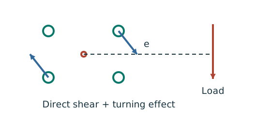
- Find direct shear and moment about the bolt-group centroid.
- Moment-induced forces act tangentially; farther bolts attract more.
- Add horizontal and vertical components before finding the resultant.
Remember: Do not simply add two force magnitudes pointing in different directions.
Source: Chapter 2 pp.21–22. The eccentric force tries to rotate the bolt group in the plane of the plate. Assume a rigid plate, equal bolts, elastic force proportional to radius and uniform direct shear. Place the origin at the bolt-group centroid. Give every bolt coordinates , measured in , with .
Why this works: if torsional force is , its resisting moment is . Summing gives , so . The torsional force is tangent to a circle, perpendicular to the radius, not radial. For vertical applied load, its vertical component at a critical corner is and horizontal component . Choose the corner where the vertical component adds to direct shear.
This is equivalent to the lecture vector formula , with for the shown vertical-load arrangement. Do not use merely because the load is vertical: torsional force is perpendicular to the radius.
Connection example 3: an eccentric bolt group in the plate plane
Open this example on its own page
Check the Grade 8.8 M24 bolt group carrying dead plus imposed load at a eccentricity. Steel is S355. Use the lecturer’s one-side-plate load model.
Original source: LectureNotes/Ch 2_Connection.pdf — p. 25, p. 26. Values tagged given are in the question or diagram; lookup values come from a named table; calculated values follow from the working; assumptions are stated explicitly.
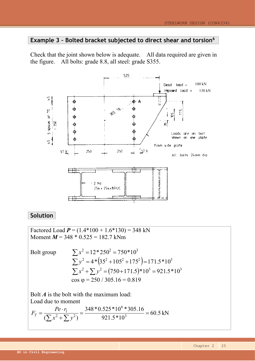
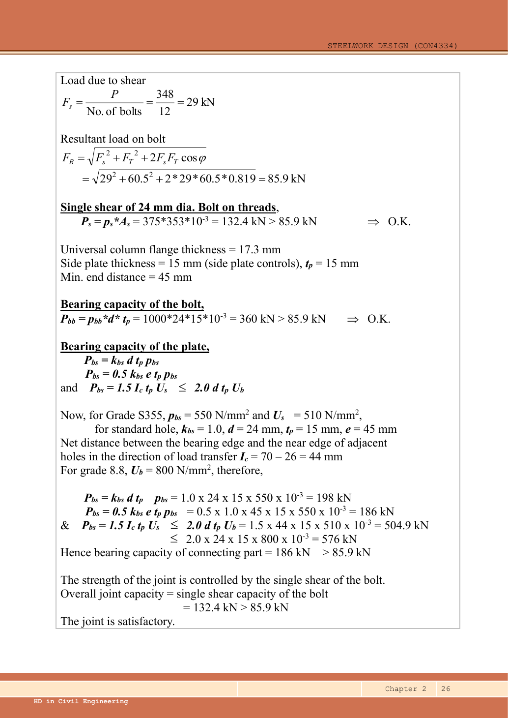
Read the diagram and collect the data
| Input | Origin |
|---|---|
| Given load/model | dead+ imposed. Drawing says bolt loads shown on one plate; do not halve the specified force again. |
| Given | horizontal distance from the dashed bolt-group centreline to vertical load line, upper dimension. |
| Coordinates | from the two dimensions. from pitch and symmetric six-row arrangement. |
| Thickness and edge | Side plate ; p.26 gives UC flange , so . Vertical end ; pitch ; hole . |
| Lookup | M24 ; ,,,,. |
Before calculating: recognition and strategy
The load rotates the plate in its own plane, so each bolt takes uniform direct shear plus tangential torsional shear. This is not a bolt-tension problem. Use centroidal coordinates, sum squared distances over all bolts, and resolve torsional force into components before adding direct shear. The far right corners have torsional vertical force in the same direction as direct shear.
1. Factored load and moment
Animation labFrom characteristic to design load
Supplement to the original lesson. Enable JavaScript to play, step through calculations and rotate 3D models. The following explanation remains readable offline.
- G is permanent load; Q is imposed load. A surface load and a line load also have different units.
- This illustration uses the course gravity case . Other combinations in the original text retain their own factors.
- For illustrative , change Q and watch each separate contribution.
- Do not carry this ULS total automatically into deflection. Follow the stated SLS load case.
2. Bolt-group polar sum and corner radius
Simple explanation: An off-centre force also tries to turn the group
Pulling away from the centre causes a push plus a twist.
- Find direct shear and moment about the bolt-group centroid.
- Moment-induced forces act tangentially; farther bolts attract more.
- Add horizontal and vertical components before finding the resultant.
Remember: Do not simply add two force magnitudes pointing in different directions.
Each bolt contributes . There are identical values. At each absolute height , , there are four bolts: two left/right positions multiplied by two positive/negative vertical positions.
Animation labAdd direct and torsional bolt forces
Supplement to the original lesson. Enable JavaScript to play, step through calculations and rotate 3D models. The following explanation remains readable offline.
- Assign signed coordinates to the bolts relative to the group centroid.
- For the equal-bolt elastic model, the direct force is per bolt.
- Moment magnitude is ; its sign follows the load direction. For signed M: , , .
- Add signed x and y components at each bolt, then take the resultant. The longest arrow shows the critical bolt in this illustration.
3. Direct force, torsion and maximum resultant
Simple explanation: Add arrows before taking the magnitude
Walking east and walking north do not point in the same direction.
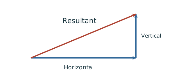
- Choose signed horizontal and vertical directions.
- Add contributions along each direction separately.
- For perpendicular components, use the right-triangle resultant.
Remember: Check the corner where direct and torsional components reinforce each other.
The units of are . The top/bottom right corners have equal resultant magnitude. Other rows have a smaller horizontal torsion component; the left column’s vertical torsion subtracts from direct shear, so it is less critical.
Animation labAdd direct and torsional bolt forces
Supplement to the original lesson. Enable JavaScript to play, step through calculations and rotate 3D models. The following explanation remains readable offline.
- Assign signed coordinates to the bolts relative to the group centroid.
- For the equal-bolt elastic model, the direct force is per bolt.
- Moment magnitude is ; its sign follows the load direction. For signed M: , , .
- Add signed x and y components at each bolt, then take the resultant. The longest arrow shows the critical bolt in this illustration.
4. Compare with single-shear bolt resistance
The source checks the side plate’s single shear interface. The plan view showing plates on both sides does not authorise doubling resistance while keeping only one side’s force model.
Animation labCount the bolt shear planes
Supplement to the original lesson. Enable JavaScript to play, step through calculations and rotate 3D models. The following explanation remains readable offline.
- Load must cross an interface between the connected plates.
- A lap joint gives one shear plane through a bolt.
- A symmetric double-cover joint may provide two shear planes. Count load-transfer interfaces, not just visible plates.
- Use the source’s area and shear strength. Then check bearing, plate resistance and detailing separately.
5. Check bolt bearing against the same resultant
Animation labBearing and the remaining ligament
Supplement to the original lesson. Enable JavaScript to play, step through calculations and rotate 3D models. The following explanation remains readable offline.
- Force transfers through contact between bolt and connected plate.
- The plate around the hole carries bearing stress. Bolt bearing and plate bearing are separate checks.
- A short ligament can tear out towards the end. The direction of force determines the relevant edge.
- Evaluate every specified bearing and ligament bound for each layer and retain the smallest applicable resistance.
6. Connected-part bounds and conclusion
Simple explanation: The bolt can crush or tear the plate
A strong bolt can still push through a weak hole edge.
- Check the bolt and each connected plate’s bearing bounds.
- Use nominal bolt diameter for bearing; hole size for removed material.
- The smallest applicable resistance controls.
Remember: A short end distance may govern even when bolt shear passes.
For the course’s specified connection checks, single-shear bolt capacity is the governing resistance per critical bolt. The ratio . This is not a total connection force capacity of : it is compared with the critical bolt force.
Animation labBearing and the remaining ligament
Supplement to the original lesson. Enable JavaScript to play, step through calculations and rotate 3D models. The following explanation remains readable offline.
- Force transfers through contact between bolt and connected plate.
- The plate around the hole carries bearing stress. Bolt bearing and plate bearing are separate checks.
- A short ligament can tear out towards the end. The direction of force determines the relevant edge.
- Evaluate every specified bearing and ligament bound for each layer and retain the smallest applicable resistance.
Compact exam answer
, . ; . , ; . Per-bolt resistances: shear , bolt bearing , plate bearing . All exceed the resultant; requested checks pass.
Mistakes to avoid
- Do not use as the complete bolt demand.
- The sum for bolt-group geometry has units , unlike weld line inertia .
- The eccentricity starts at the group centroid, not the right bolt column.
- Add force components; is not the actual resultant.
Procedure for an unfamiliar variant
- Locate centroid and write every bolt coordinate.
- Compute factored , centroidal eccentricity and .
- Sum all and resolve into components.
- Find the corner where torsion adds to direct shear.
- Compare that resultant with shear and all bearing limits.
Independent self-check
Try it yourself. If both characteristic loads increase by with unchanged geometry, how does the critical bolt force change?
Reveal answer and reasoning
and each multiply by ; every direct/torsional component does too. , still below . Capacity is unchanged.
Animation labAdd direct and torsional bolt forces
Supplement to the original lesson. Enable JavaScript to play, step through calculations and rotate 3D models. The following explanation remains readable offline.
- Assign signed coordinates to the bolts relative to the group centroid.
- For the equal-bolt elastic model, the direct force is per bolt.
- Moment magnitude is ; its sign follows the load direction. For signed M: , , .
- Add signed x and y components at each bolt, then take the resultant. The longest arrow shows the critical bolt in this illustration.
Animation labAdd direct and torsional bolt forces
Supplement to the original lesson. Enable JavaScript to play, step through calculations and rotate 3D models. The following explanation remains readable offline.
- Assign signed coordinates to the bolts relative to the group centroid.
- For the equal-bolt elastic model, the direct force is per bolt.
- Moment magnitude is ; its sign follows the load direction. For signed M: , , .
- Add signed x and y components at each bolt, then take the resultant. The longest arrow shows the critical bolt in this illustration.
Out-of-plane brackets: shear plus tension
Simple explanation: Two passing checks may still interact
One bolt is doing two jobs at the same time.
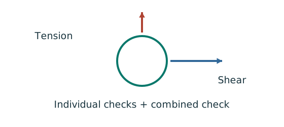
- Check shear on its own and tension on its own.
- Calculate the course’s combined-action expression.
- Apply its own limit, not a limit borrowed from columns.
Remember: The supplied bolt interaction limit of 1.4 does not replace the individual checks.
Source: Chapter 2 pp.23–24. Here the bracket pulls the plate away from the support and rotates about a bottom contact/bolt line in the lecture approximation. Measure each bolt-row distance from that assumed rotation line. The bottom row has and no moment-induced tension in this model, but still carries direct shear.
For two identical vertical rows of bolts, for one row. Do not multiply by again when the sum already includes both rows. The individual limits remain compulsory: a sum below alone does not excuse excessive tension or shear. Bearing also needs checking where the connection data permit it.
Connection example 4: bracket bolts in shear and tension
Open this example on its own page
Check ten Grade 8.8 M16 bolts supporting a ultimate bracket load at eccentricity. Five bolts are arranged vertically on each side at centres. Steel is S355.
Original source: LectureNotes/Ch 2_Connection.pdf — p. 27, p. 28. Values tagged given are in the question or diagram; lookup values come from a named table; calculated values follow from the working; assumptions are stated explicitly.
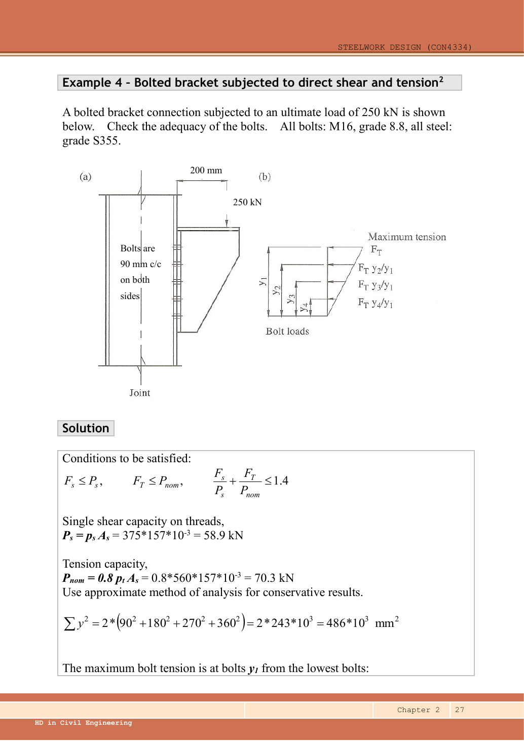
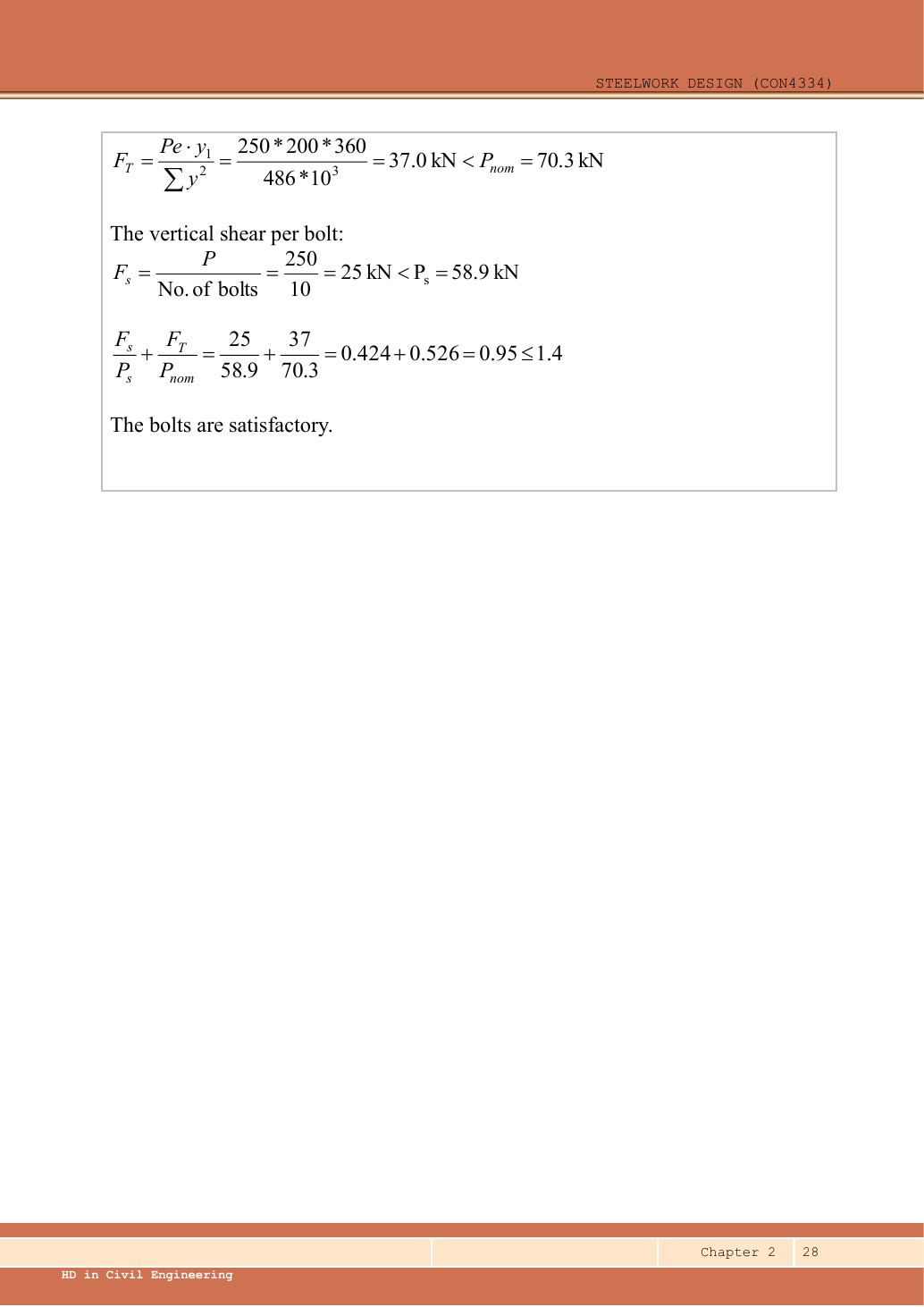
Read the diagram and collect the data
| Input | Origin |
|---|---|
| Given load | ultimate; the downward arrow is outside the connection plane. |
| Given bolt arrangement | Five bolts per side; two sides; between consecutive rows; total . |
| Calculated row distances | On each side, measure upwards from the bottom rotation line: . |
| Lookup | M16 , Grade 8.8 and (Ch 2 pp.3,9–10). |
| Model assumption | Rigid bracket and linear tensile-force distribution about bottom bolt line, as stated in the lecturer approximation; use nominal tension . |
Before calculating: recognition and strategy
The load pulls the upper bolts along their axes while all bolts carry vertical shear. Use an out-of-plane rotation model, not the centroidal in-plane torsion formula. Check shear, tension and their interaction separately. The task’s bolt calculation does not provide the full plate/gauge dimensions needed for a complete joint/prying and bearing verification.
1. Find bolt shear and nominal tension resistance
The reduction is part of the adopted simplified model. Do not substitute in the nominal-tension interaction denominator.
Animation labOut-of-plane bolt tension and prying
Supplement to the original lesson. Enable JavaScript to play, step through calculations and rotate 3D models. The following explanation remains readable offline.
- A bracket moment can create compression at the plate contact and tension in the bolt rows.
- The original assumed pivot/compression line determines each row distance.
- Under the elastic row model, a farther tension row attracts more tension. Direct shear may act simultaneously.
- Flexible plates can add prying force. Use nominal tension and interaction rules exactly as specified by the course.
2. Sum squared distances about the bottom row
Each of the two vertical sides has the same distances. The bottom row contributes to moment resistance but remains in the count for direct shear.
Animation labOut-of-plane bolt tension and prying
Supplement to the original lesson. Enable JavaScript to play, step through calculations and rotate 3D models. The following explanation remains readable offline.
- A bracket moment can create compression at the plate contact and tension in the bolt rows.
- The original assumed pivot/compression line determines each row distance.
- Under the elastic row model, a farther tension row attracts more tension. Direct shear may act simultaneously.
- Flexible plates can add prying force. Use nominal tension and interaction rules exactly as specified by the course.
3. Maximum tension is in the top row
Simple explanation: Why the top bolt row is pulled hardest
The bracket tries to peel away from the support about the assumed contact line.
- Use the rotation/contact line assumed by the course model.
- Measure each bolt row’s distance from that line.
- Check maximum tension, direct shear and their interaction.
Remember: A row at the pivot can still carry direct shear.
Tension varies in proportion to distance . Let ; moment equilibrium gives . Thus and the top bolt at has the largest tension.
Animation labOut-of-plane bolt tension and prying
Supplement to the original lesson. Enable JavaScript to play, step through calculations and rotate 3D models. The following explanation remains readable offline.
- A bracket moment can create compression at the plate contact and tension in the bolt rows.
- The original assumed pivot/compression line determines each row distance.
- Under the elastic row model, a farther tension row attracts more tension. Direct shear may act simultaneously.
- Flexible plates can add prying force. Use nominal tension and interaction rules exactly as specified by the course.
4. Uniform direct shear
Animation labCount the bolt shear planes
Supplement to the original lesson. Enable JavaScript to play, step through calculations and rotate 3D models. The following explanation remains readable offline.
- Load must cross an interface between the connected plates.
- A lap joint gives one shear plane through a bolt.
- A symmetric double-cover joint may provide two shear planes. Count load-transfer interfaces, not just visible plates.
- Use the source’s area and shear strength. Then check bearing, plate resistance and detailing separately.
5. Combined action and conclusion
Simple explanation: Two passing checks may still interact
One bolt is doing two jobs at the same time.
- Check shear on its own and tension on its own.
- Calculate the course’s combined-action expression.
- Apply its own limit, not a limit borrowed from columns.
Remember: The supplied bolt interaction limit of 1.4 does not replace the individual checks.
The bolts satisfy all three calculated shear/tension conditions under the lecturer’s approximate model. This is the requested bolt result. Plate thickness, detailed bearing-edge geometry and flange gauge are not supplied sufficiently to certify every other joint limit state; do not claim those have been checked.
Animation labOut-of-plane bolt tension and prying
Supplement to the original lesson. Enable JavaScript to play, step through calculations and rotate 3D models. The following explanation remains readable offline.
- A bracket moment can create compression at the plate contact and tension in the bolt rows.
- The original assumed pivot/compression line determines each row distance.
- Under the elastic row model, a farther tension row attracts more tension. Direct shear may act simultaneously.
- Flexible plates can add prying force. Use nominal tension and interaction rules exactly as specified by the course.
Compact exam answer
; . about bottom bolt line. . . Individual limits pass and interaction. Bolts are adequate under the specified approximate shear/tension model.
Mistakes to avoid
- Do not factor again.
- Do not measure from the group centroid for this bottom-pivot model.
- Do not omit the bottom bolts from direct shear.
- Passing the interaction does not replace individual shear/tension limits.
Procedure for an unfamiliar variant
- Identify out-of-plane rotation and the stated pivot.
- Write all distances and include all physical bolts in .
- Calculate maximum tension and uniform shear.
- Check each individual resistance and then the interaction.
- State the model and any unprovided plate/prying information.
Independent self-check
Try it yourself. Move the same load to eccentricity. Does the existing bolt group pass?
Reveal answer and reasoning
Tension doubles to , exceeding . Interaction becomes . Both tension and interaction fail; shear remains .
Animation labOut-of-plane bolt tension and prying
Supplement to the original lesson. Enable JavaScript to play, step through calculations and rotate 3D models. The following explanation remains readable offline.
- A bracket moment can create compression at the plate contact and tension in the bolt rows.
- The original assumed pivot/compression line determines each row distance.
- Under the elastic row model, a farther tension row attracts more tension. Direct shear may act simultaneously.
- Flexible plates can add prying force. Use nominal tension and interaction rules exactly as specified by the course.
Connection example 5: separate moment and shear bolt groups
Open this example on its own page
Design the bolt groups joining a UB floor beam to a UC. Steel is S355 and bolts are Grade 8.8 M24. Characteristic moments are dead and imposed; characteristic shears are dead and imposed.
Original source: LectureNotes/Ch 2_Connection.pdf — p. 29, p. 30. Values tagged given are in the question or diagram; lookup values come from a named table; calculated values follow from the working; assumptions are stated explicitly.
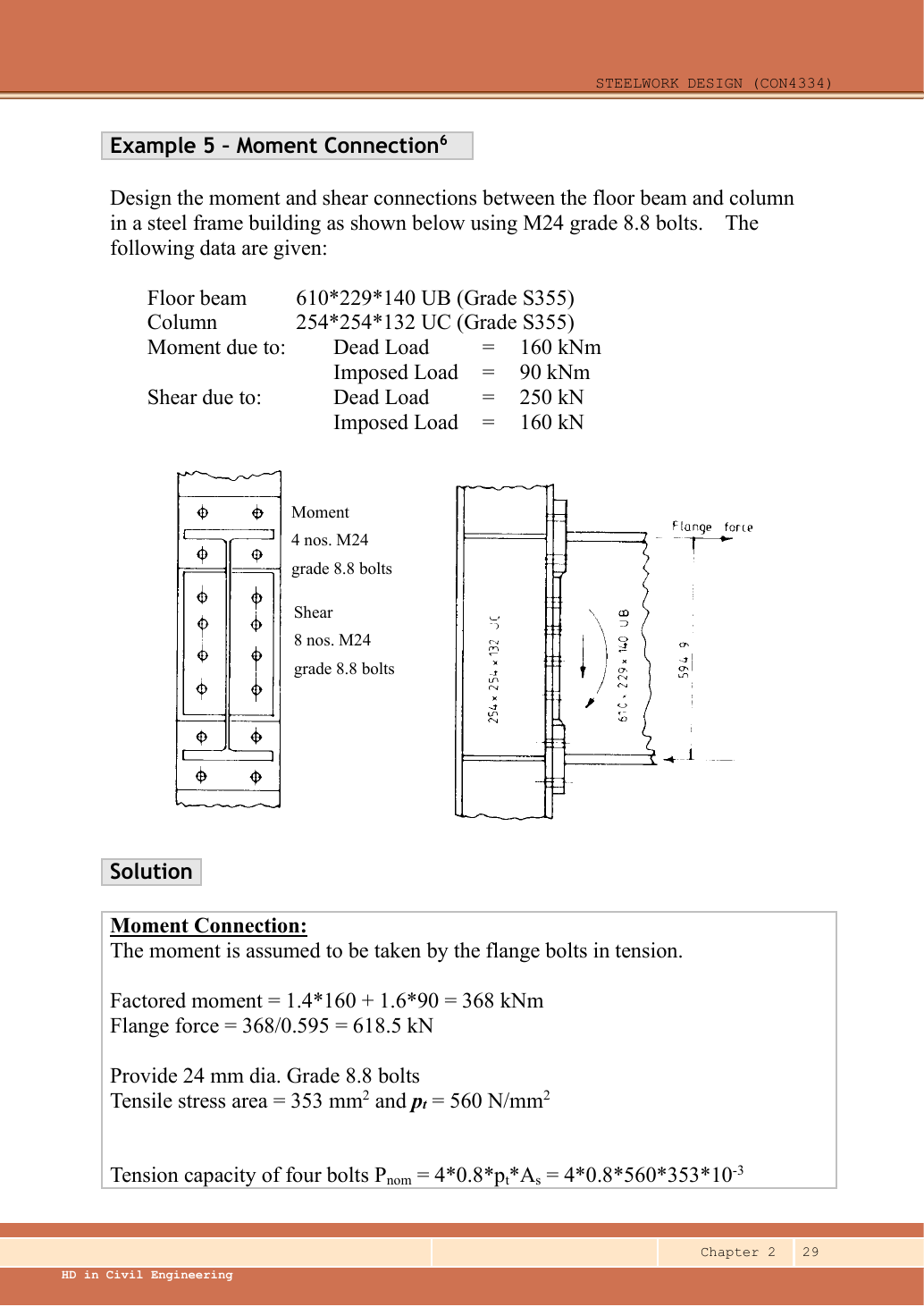
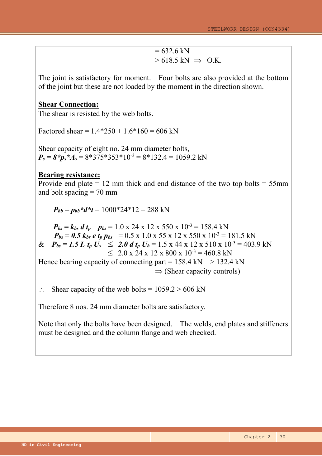
Read the diagram and collect the data
| Input | Origin |
|---|---|
| Given actions | Separate moment and shear dead/imposed components in question table; factor each once. |
| Given force-couple arm | between flange force lines in lecturer diagram/solution; not the nominal beam depth. |
| Selected fasteners | Four upper flange bolts; four lower for opposite moment direction; eight web bolts, all M24. |
| Selected bearing detail | Lecturer p.30 selects end plate, end distance and pitch. These are design choices, not task givens. |
| Lookup | M24 ; Grade 8.8 ,,; S355 ,; . |
Before calculating: recognition and strategy
Use the source idealisation: bending is a tension/compression force couple at the flanges; vertical shear is carried by a separate web-bolt group. Moment divided by the perpendicular couple arm gives flange force. Because groups have separate assigned actions, do not distribute the flange tensile force among the web bolts.
1. Design the tension flange group
Simple explanation: How two flange forces make a moment
Two opposite forces form a turning pair, like two hands turning a wheel.
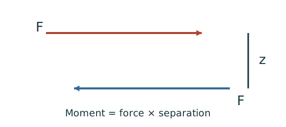
- Identify the separation between their actual force lines.
- Required force equals moment divided by that separation.
- Design the relevant flange group for that force.
Remember: The force-line separation is not automatically the overall section depth.
For the moment direction shown, the lower flange region supplies compression and the upper group tension. The extra lower four bolts are not added to the upper group’s capacity; they provide the corresponding group for the opposite moment direction/detail.
Animation labOut-of-plane bolt tension and prying
Supplement to the original lesson. Enable JavaScript to play, step through calculations and rotate 3D models. The following explanation remains readable offline.
- A bracket moment can create compression at the plate contact and tension in the bolt rows.
- The original assumed pivot/compression line determines each row distance.
- Under the elastic row model, a farther tension row attracts more tension. Direct shear may act simultaneously.
- Flexible plates can add prying force. Use nominal tension and interaction rules exactly as specified by the course.
2. Design the shear group
Simple explanation: Count where the bolt can be sheared
The plate interfaces are the places trying to cut across the bolt.
- Count actual loaded shear planes, not merely visible plates.
- Choose shank or threaded area for the plane concerned.
- Compare group resistance with the force that group transfers.
Remember: Bolts on opposite sides of a splice do not all act in parallel.
Animation labCount the bolt shear planes
Supplement to the original lesson. Enable JavaScript to play, step through calculations and rotate 3D models. The following explanation remains readable offline.
- Load must cross an interface between the connected plates.
- A lap joint gives one shear plane through a bolt.
- A symmetric double-cover joint may provide two shear planes. Count load-transfer interfaces, not just visible plates.
- Use the source’s area and shear strength. Then check bearing, plate resistance and detailing separately.
3. Check selected end-plate bearing
Use and standard hole . The chosen plate and pitch give clear ligament . The chosen end distance is .
Both bearing resistances exceed the per-bolt demand and also exceed the shear resistance, so shear governs the web group.
Animation labBearing and the remaining ligament
Supplement to the original lesson. Enable JavaScript to play, step through calculations and rotate 3D models. The following explanation remains readable offline.
- Force transfers through contact between bolt and connected plate.
- The plate around the hole carries bearing stress. Bolt bearing and plate bearing are separate checks.
- A short ligament can tear out towards the end. The direction of force determines the relevant edge.
- Evaluate every specified bearing and ligament bound for each layer and retain the smallest applicable resistance.
4. State what has actually been designed
Simple explanation: What to do when one input is missing
A calculator cannot supply a dimension that the drawing never gave.
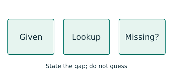
- Separate given values, table values and calculated values.
- Complete the checks whose required inputs are available.
- State the missing input beside the remaining conditional result.
Remember: An illustrative assumption must not become an unstated exam given.
The flange tension and web shear/bearing bolt checks pass under the source’s force-couple idealisation. The source explicitly says only bolts have been designed; welds, end plates, stiffeners, column flange and column web require separate design. The end-plate bearing calculation is not a complete end-plate bending/prying check.
Animation labSeparate the moment couple and shear
Supplement to the original lesson. Enable JavaScript to play, step through calculations and rotate 3D models. The following explanation remains readable offline.
- A simplified moment connection assigns different actions to different fastener groups.
- Opposite flange forces separated by z resist moment: .
- The web fasteners or welds carry the assigned vertical shear in this model.
- Flange force, web shear, plate bearing and detailing each need their specified checks.
Compact exam answer
ULS ; flange force. Four M24 Grade 8.8 flange bolts give nominal tension . ULS ; eight M24 web bolts give shear . Selected plate gives bolt bearing and plate bearing per bolt, both. Bolts pass; remaining connection components are outside the source calculation.
Mistakes to avoid
- Use force-couple arm, not nominal beam depth .
- Do not add bottom compression-side bolts to the upper tensile group.
- Do not call the end plate fully designed after checking only bearing.
Procedure for an unfamiliar variant
- Factor moment and shear components separately.
- Resolve bending moment into flange force using the stated couple arm.
- Size the tension group using nominal bolt tension.
- Assign shear to the web group and check its bearing path.
- Document which other joint components are not included in the bolt-only exercise.
Independent self-check
Try it yourself. If the ultimate moment becomes , keeping arm and four flange bolts, is the tension group adequate?
Reveal answer and reasoning
, so no. Required count; at least by strength alone, but the final symmetric layout and plate/prying design must also be revised.
Animation labOut-of-plane bolt tension and prying
Supplement to the original lesson. Enable JavaScript to play, step through calculations and rotate 3D models. The following explanation remains readable offline.
- A bracket moment can create compression at the plate contact and tension in the bolt rows.
- The original assumed pivot/compression line determines each row distance.
- Under the elastic row model, a farther tension row attracts more tension. Direct shear may act simultaneously.
- Flexible plates can add prying force. Use nominal tension and interaction rules exactly as specified by the course.
Animation labOut-of-plane bolt tension and prying
Supplement to the original lesson. Enable JavaScript to play, step through calculations and rotate 3D models. The following explanation remains readable offline.
- A bracket moment can create compression at the plate contact and tension in the bolt rows.
- The original assumed pivot/compression line determines each row distance.
- Under the elastic row model, a farther tension row attracts more tension. Direct shear may act simultaneously.
- Flexible plates can add prying force. Use nominal tension and interaction rules exactly as specified by the course.
Long joints and large grip
Source: Chapter 2 p.24. Connections with more than two bolts and joint length over require a shear-capacity reduction under the cited Clause 9.3.6.1.4. For ordinary bolts, total connected-ply thickness above five bolt diameters invokes the large-grip provision in Clause 9.3.6.1.5. The actual reduction equations are not reproduced in the supplied materials. Recognise the trigger, identify the missing clause information and avoid inventing a coefficient. None of the standard concentric splice examples here should be treated as an unrestricted formula for arbitrarily long connections.
Animation labLoad sharing along a long joint
Supplement to the original lesson. Enable JavaScript to play, step through calculations and rotate 3D models. The following explanation remains readable offline.
- Several bolts share a connection force, but a long joint need not distribute it perfectly evenly.
- Compatibility between the connected plates influences force attracted by bolts near the ends.
- Joint length is measured along the load path; grip is through the connected thickness.
- Apply long-joint or large-grip provisions only when their conditions are met. Arrows here are qualitative.
Fillet weld throat and capacity
Simple explanation: Why the weld throat is smaller than its leg
The shortest cut through the weld is thinner than the outside leg.
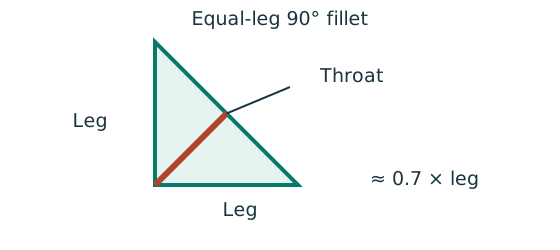
- For the stated equal-leg 90° fillet, throat is approximately 0.7 × leg.
- Multiply throat area by the matching weld design strength.
- For force per length, use a one-millimetre weld strip.
Remember: Choose strength from both the steel grade and electrode class.
Source: Chapter 2 pp.31–33. A fillet with equal legs has effective throat . The throat is the critical shortest section through the weld. The simplified method compares the resultant force per unit length with the throat resistance per unit length.
For S355 with Class 42 electrode the supplied Table 9.2a gives . Select both the parent-steel row and electrode-class column. “42” is not . The supplied S275 columns use ; S460 with Class 50 uses .
The directional method splits force per unit length into longitudinal and transverse resultant . ,, where , is the force-to-throat angle specified in Figure 9.4. Check . The numerical fillet-weld examples on this site use the lecturer’s simplified method, so do not add the directional-method enhancement.
Animation labFrom fillet leg to effective throat
Supplement to the original lesson. Enable JavaScript to play, step through calculations and rotate 3D models. The following explanation remains readable offline.
- An equal-leg fillet between perpendicular plates has an approximately right-triangular section.
- For this geometry, throat . It is shorter than the leg.
- Effective resisting area = . With here, capacity per length is .
- Use the course end allowances, minimum size and length rules; increasing the geometric length alone does not resolve every detailing check.
Unnumbered example: a S355/Class 42 fillet
Simple explanation: Keep the units on the same scale
Changing units is like changing the ruler, not the object.
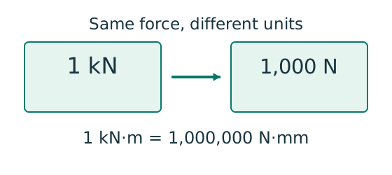
- ; .
- Area needs two length conversions; inertia needs four.
- Convert before substituting, then check the final unit.
Remember: A kN·m moment becomes 1,000,000 N·mm, not 1,000.
Source: Chapter 2 p.31 and L2 slide 6. Required result: strength per millimetre of weld. Given leg and material/electrode combination; lookup from Table 9.2a, S355 row/Class 42 column.
Throat area in a one-millimetre strip
A one-millimetre strip has throat area . First calculate the throat; this is why the factor appears.
Animation labFrom fillet leg to effective throat
Supplement to the original lesson. Enable JavaScript to play, step through calculations and rotate 3D models. The following explanation remains readable offline.
- An equal-leg fillet between perpendicular plates has an approximately right-triangular section.
- For this geometry, throat . It is shorter than the leg.
- Effective resisting area = . With here, capacity per length is .
- Use the course end allowances, minimum size and length rules; increasing the geometric length alone does not resolve every detailing check.
Multiply throat area by design strength
Exam script: . This is capacity per effective length; multiply by effective weld length for total capacity.
Animation labFrom fillet leg to effective throat
Supplement to the original lesson. Enable JavaScript to play, step through calculations and rotate 3D models. The following explanation remains readable offline.
- An equal-leg fillet between perpendicular plates has an approximately right-triangular section.
- For this geometry, throat . It is shorter than the leg.
- Effective resisting area = . With here, capacity per length is .
- Use the course end allowances, minimum size and length rules; increasing the geometric length alone does not resolve every detailing check.
Try it yourself. What is the corresponding strength of an weld with the same materials?
Reveal answer and reasoning
. . Capacity scales with leg size when materials remain the same.
Animation labFrom fillet leg to effective throat
Supplement to the original lesson. Enable JavaScript to play, step through calculations and rotate 3D models. The following explanation remains readable offline.
- An equal-leg fillet between perpendicular plates has an approximately right-triangular section.
- For this geometry, throat . It is shorter than the leg.
- Effective resisting area = . With here, capacity per length is .
- Use the course end allowances, minimum size and length rules; increasing the geometric length alone does not resolve every detailing check.
Animation labFrom fillet leg to effective throat
Supplement to the original lesson. Enable JavaScript to play, step through calculations and rotate 3D models. The following explanation remains readable offline.
- An equal-leg fillet between perpendicular plates has an approximately right-triangular section.
- For this geometry, throat . It is shorter than the leg.
- Effective resisting area = . With here, capacity per length is .
- Use the course end allowances, minimum size and length rules; increasing the geometric length alone does not resolve every detailing check.
Effective length, minimum sizes, laps and returns
Simple explanation: Drawn length and useful length differ
The start and end of a weld are not credited as fully effective in this course model.
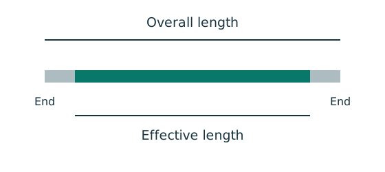
- Find the effective length required by strength.
- Add the specified end allowance to each separate run.
- Round up, then check minimum size, spacing and returns.
Remember: Strength alone does not prove a weld detail is acceptable.
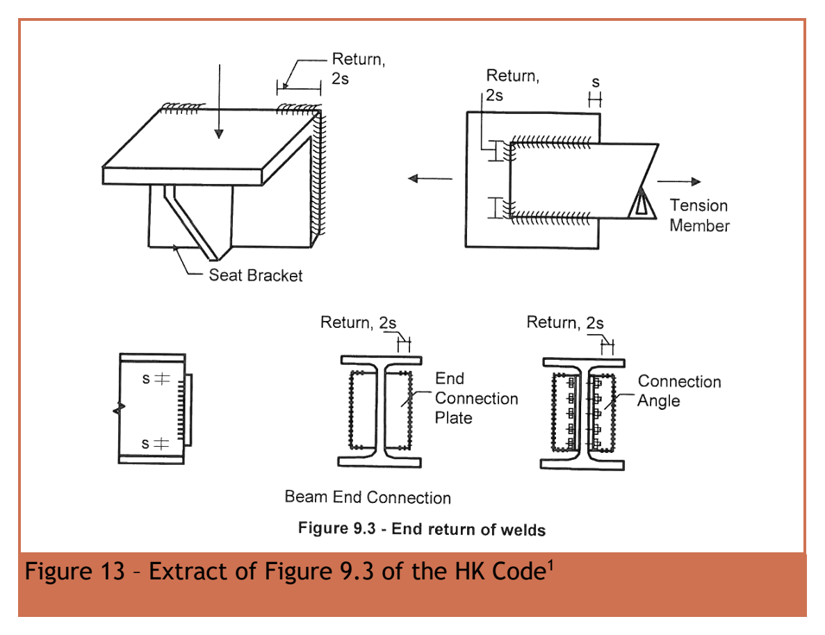
Source: Chapter 2 pp.33–34. For the lecture straight welds, effective length . The deduction represents ineffective starts/ends. If designing length, add to the required effective length, then round up. Apply it to each separately counted run, not once to the entire connection.
The minimum effective length is the greater of and . The notes’ minimum leg table based on the thicker part is through thickness, for –, for –, and over . For a weld along a plate edge, maximum leg is plate thickness for thin plate below ; for plate equal to or thicker than , the maximum is thickness minus . Do not increase a weld indefinitely on a thin angle edge.
Provide corner returns at least , consistent with the source diagram and worked detailing (the prose at p.33 omits “not” before “less than”). Lap length is at least , where is the thinner plate. The source also requires longitudinal weld length at least the transverse spacing between welds. Long lap joints over have further source-clause provisions; intermittent welds are unsuitable for fatigue conditions, and the notes limit unwelded gaps to / in compression or / in tension. Check the stated detail, not just total weld strength.
Connection example 6: balance two weld lengths about the load line
Open this example on its own page
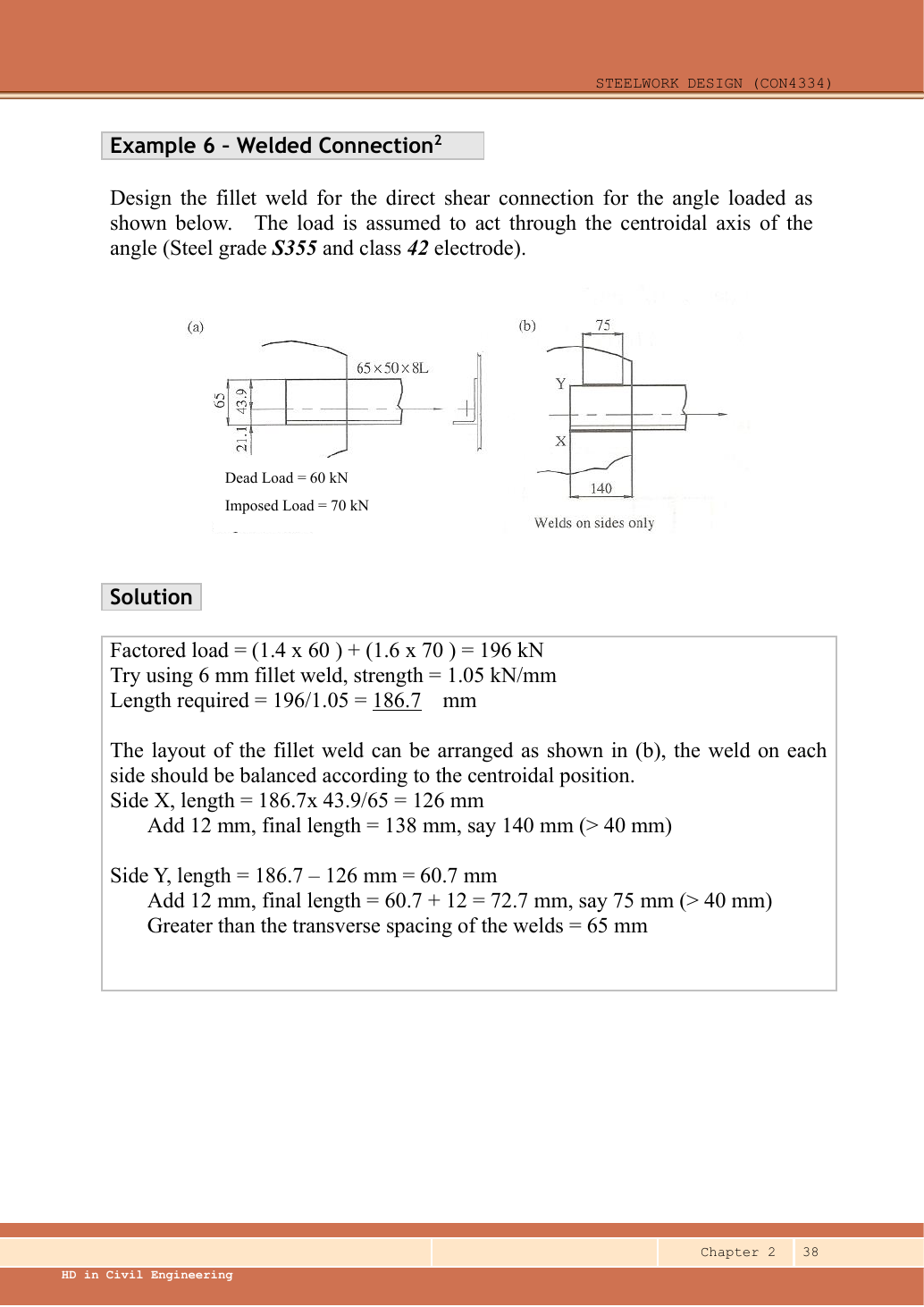
Design the side fillet welds for a angle carrying characteristic dead tension and characteristic imposed tension through its centroid. Use S355 steel and Class 42 electrode.
Original source: LectureNotes/Ch 2_Connection.pdf — p. 38. Values tagged given are in the question or diagram; lookup values come from a named table; calculated values follow from the working; assumptions are stated explicitly.
Read the diagram and collect the data
| Input | Origin |
|---|---|
| Given loads | dead, imposed, arrows through dashed centroidal axis. |
| Given geometry | The left sketch labels L; connected-leg width , centroid distance and . |
| Design choice | Lecturer tries fillet and final side lengths (X), (Y), shown at right. |
| Lookup | Table 9.2a, S355 row/Class 42 column: . Throat . |
Before calculating: recognition and strategy
A longer weld must be put on the side closer to the load line. Treat the two parallel weld lines as supports of the tensile force across the separation: force equilibrium gives ; moment equilibrium about X gives . Equal weld lengths would move the connection resultant away from the angle centroid.
1. Factored tensile force
Animation labFrom characteristic to design load
Supplement to the original lesson. Enable JavaScript to play, step through calculations and rotate 3D models. The following explanation remains readable offline.
- G is permanent load; Q is imposed load. A surface load and a line load also have different units.
- This illustration uses the course gravity case . Other combinations in the original text retain their own factors.
- For illustrative , change Q and watch each separate contribution.
- Do not carry this ULS total automatically into deflection. Follow the stated SLS load case.
2. Select a trial leg and find capacity per length
Simple explanation: Why the weld throat is smaller than its leg
The shortest cut through the weld is thinner than the outside leg.
- For the stated equal-leg 90° fillet, throat is approximately 0.7 × leg.
- Multiply throat area by the matching weld design strength.
- For force per length, use a one-millimetre weld strip.
Remember: Choose strength from both the steel grade and electrode class.
The angle edge thickness is , so the source maximum edge-weld leg permits this selection. The supporting plate thickness is not given; its effect on the minimum weld-size rule remains a detailing condition.
Animation labFrom fillet leg to effective throat
Supplement to the original lesson. Enable JavaScript to play, step through calculations and rotate 3D models. The following explanation remains readable offline.
- An equal-leg fillet between perpendicular plates has an approximately right-triangular section.
- For this geometry, throat . It is shorter than the leg.
- Effective resisting area = . With here, capacity per length is .
- Use the course end allowances, minimum size and length rules; increasing the geometric length alone does not resolve every detailing check.
3. Share force and effective length between the sides
Simple explanation: Why two weld lengths can be unequal
Two side welds must balance the load about its actual line of action.
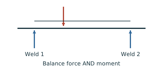
- Find the load line and the lever arm to each weld.
- Balance moments as well as the total force.
- Convert each weld’s force into its own required length.
Remember: Equal-looking legs do not justify equal weld forces without equilibrium.
Check: the forces sum and the required lengths sum . The larger opposite lever arm produces the larger SideX force.
Animation labBalance two weld forces
Supplement to the original lesson. Enable JavaScript to play, step through calculations and rotate 3D models. The following explanation remains readable offline.
- The angle centroid/load line is generally not halfway between the two weld runs.
- . Both weld runs contribute to the applied force.
- . The run nearer the load line carries more force.
- For equal throat resistance per length, the required effective lengths follow the same ratio. Add detailing allowances afterwards.
4. Add end allowances, round up and check the actual lengths
Simple explanation: Drawn length and useful length differ
The start and end of a weld are not credited as fully effective in this course model.
- Find the effective length required by strength.
- Add the specified end allowance to each separate run.
- Round up, then check minimum size, spacing and returns.
Remember: Strength alone does not prove a weld detail is acceptable.
Each effective length exceeds . The physical side lengths and also exceed the transverse separation, matching the source detailing check. The extra rounding increases available resistance; the actual force split still follows equilibrium. End-return/support-plate details are not fully specified, so this is the completed requested side-weld strength/length design, not a complete fabrication detail.
Animation labFrom fillet leg to effective throat
Supplement to the original lesson. Enable JavaScript to play, step through calculations and rotate 3D models. The following explanation remains readable offline.
- An equal-leg fillet between perpendicular plates has an approximately right-triangular section.
- For this geometry, throat . It is shorter than the leg.
- Effective resisting area = . With here, capacity per length is .
- Use the course end allowances, minimum size and length rules; increasing the geometric length alone does not resolve every detailing check.
Compact exam answer
. Use fillet, . Force split X/Y=/. Required effective lengths /. Add to each and provide (X), (Y); effective capacities / exceed the assigned forces.
Mistakes to avoid
- Read the angle label: the source says thick, not .
- Use the opposite centroid lever arm when allocating weld force.
- Add separately to both weld runs.
- Do not use total capacity alone if one side is too short.
Procedure for an unfamiliar variant
- Locate the centroidal load line and both weld lines.
- Factor loads and select a permitted trial weld leg.
- Use force and moment equilibrium for the two side forces.
- Divide each force by weld strength per length.
- Add individual end deductions back, round up, and recheck each side.
Independent self-check
Try it yourself. Suppose the same force acts midway between the -spaced weld lines. What physical length is required on each side for weld?
Reveal answer and reasoning
Each side takes . Required effective length. Add ; choose each. Centred loading makes equal lengths appropriate.
Animation labBalance two weld forces
Supplement to the original lesson. Enable JavaScript to play, step through calculations and rotate 3D models. The following explanation remains readable offline.
- The angle centroid/load line is generally not halfway between the two weld runs.
- . Both weld runs contribute to the applied force.
- . The run nearer the load line carries more force.
- For equal throat resistance per length, the required effective lengths follow the same ratio. Add detailing allowances afterwards.
Connection example 9: a welded single unequal angle
Open this example on its own page
Check a S355 single angle connected by its long leg under dead plus imposed tension, and design the two side welds with Class 42 electrode.
Original source: LectureNotes/Ch 2_Connection.pdf — p. 42. Values tagged given are in the question or diagram; lookup values come from a named table; calculated values follow from the working; assumptions are stated explicitly.
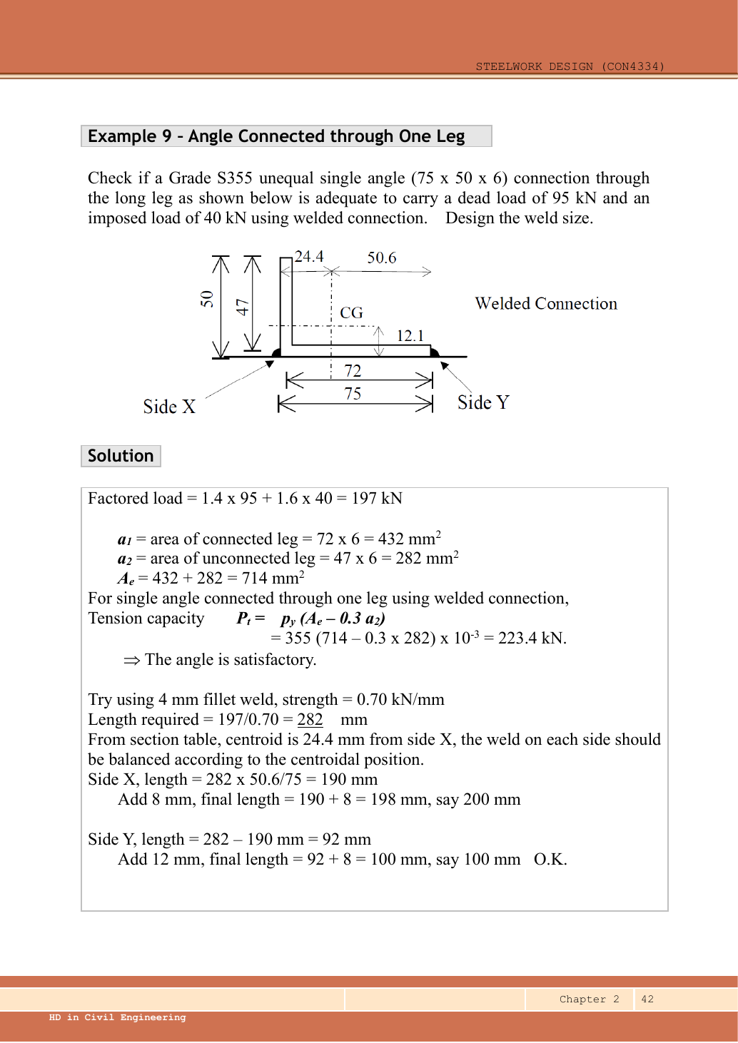
Read the diagram and collect the data
| Input | Origin |
|---|---|
| Given loads | dead and imposed, task text. |
| Given dimensions | angle; source diagram shows and half-heel widths and centroid height. |
| Lookup centroid | from SideX stated from section table in solution and labelled in diagram. Opposite arm . |
| Lookup strengths | S355 thickness → ; S355/Class 42 →. |
| Design choice | fillet, physical lengths (X), (Y), lecturer solution. |
Before calculating: recognition and strategy
First check that the angle itself can carry the force: stronger welds cannot cure a weak angle. With no bolt holes, the gross area is effective, but a single welded connected leg still has the reduction for the unconnected leg. Then balance the two parallel weld forces about the centroid using their opposite lever arms.
1. Factored force and welded-angle resistance
Simple explanation: One connected leg does not load both legs equally
The connected leg receives the pull first; the other leg receives it through the angle.
- Identify connected and outstanding legs from the drawing.
- Use the relevant bolted or welded angle rule.
- Keep the lecturer’s area convention consistent.
Remember: Bolted and welded reduction expressions are not the same rule.
The factor comes from the single welded angle rule on Ch 2 p.14. The bolted value would be a different connection model.
Animation labWhy a connected angle leg matters
Supplement to the original lesson. Enable JavaScript to play, step through calculations and rotate 3D models. The following explanation remains readable offline.
- Locate the connected leg, outstanding leg and centroid before using the table.
- Only the connected leg directly receives the fastener force.
- The outstanding area may not become equally effective at the same section; this motivates the effective-area rule.
- Bolted, welded, single-angle and double-angle details can have different rules. Preserve the formula attached to the original case.
2. Trial weld and balanced required lengths
Simple explanation: Why two weld lengths can be unequal
Two side welds must balance the load about its actual line of action.
- Find the load line and the lever arm to each weld.
- Balance moments as well as the total force.
- Convert each weld’s force into its own required length.
Remember: Equal-looking legs do not justify equal weld forces without equilibrium.
The centroid height is visible in the section but is not the transverse lever arm for sharing these two side-weld forces. The side-to-side /50.6 dimensions are the relevant ones.
Animation labBalance two weld forces
Supplement to the original lesson. Enable JavaScript to play, step through calculations and rotate 3D models. The following explanation remains readable offline.
- The angle centroid/load line is generally not halfway between the two weld runs.
- . Both weld runs contribute to the applied force.
- . The run nearer the load line carries more force.
- For equal throat resistance per length, the required effective lengths follow the same ratio. Add detailing allowances afterwards.
3. Final lengths, capacities and source correction
Simple explanation: Drawn length and useful length differ
The start and end of a weld are not credited as fully effective in this course model.
- Find the effective length required by strength.
- Add the specified end allowance to each separate run.
- Round up, then check minimum size, spacing and returns.
Remember: Strength alone does not prove a weld detail is acceptable.
Both effective lengths exceed , and both physical lengths exceed separation. For the angle edge the maximum leg is , matching the selection. The minimum-size rule depends on the unknown supporting plate thickness; do not assume it from the sketch.
Animation labFrom fillet leg to effective throat
Supplement to the original lesson. Enable JavaScript to play, step through calculations and rotate 3D models. The following explanation remains readable offline.
- An equal-leg fillet between perpendicular plates has an approximately right-triangular section.
- For this geometry, throat . It is shorter than the leg.
- Effective resisting area = . With here, capacity per length is .
- Use the course end allowances, minimum size and length rules; increasing the geometric length alone does not resolve every detailing check.
Compact exam answer
. Welded single-angle capacity. Use fillets with . Required effective X/Y lengths /. Provide / physical lengths (/ effective), giving / against /. Angle and weld strength pass; support-thickness detailing is unprovided.
Mistakes to avoid
- Do not subtract holes from a welded angle with no holes.
- The unconnected leg still needs the reduction.
- For the weld, the source writes “Add 12” (add ) is a textual error; it should be .
- Do not use centroid height in the transverse weld-force split.
Procedure for an unfamiliar variant
- Check angle area and the appropriate welded single-leg resistance.
- Read centroid location from the source/table.
- Select a weld leg permitted by the angle edge.
- Balance side forces, calculate effective lengths, then add to each.
- Verify each rounded side and the detailing conditions.
Independent self-check
Try it yourself. If the imposed load rises to , do the existing / welds still pass?
Reveal answer and reasoning
. SideX demand; SideY. Both weld sides fail although angle capacity 223.437 still passes.
Animation labBalance two weld forces
Supplement to the original lesson. Enable JavaScript to play, step through calculations and rotate 3D models. The following explanation remains readable offline.
- The angle centroid/load line is generally not halfway between the two weld runs.
- . Both weld runs contribute to the applied force.
- . The run nearer the load line carries more force.
- For equal throat resistance per length, the required effective lengths follow the same ratio. Add detailing allowances afterwards.
Connection example 10: welded splice and a minimum-size discrepancy
Open this example on its own page
Design a welded double-cover splice transferring ultimate tension between S355 main plates. Cover thickness is . Use Class 42 electrode. Explain the lecturer’s -weld solution, then reconcile it with the chapter’s minimum weld-size table.
Original source: LectureNotes/Ch 2_Connection.pdf — p. 43, p. 44. Values tagged given are in the question or diagram; lookup values come from a named table; calculated values follow from the working; assumptions are stated explicitly.
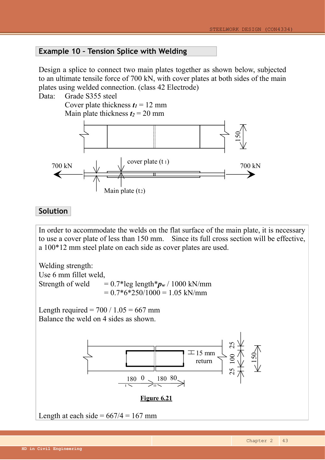
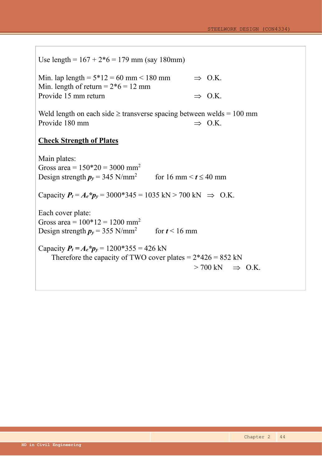
Read the diagram and collect the data
| Input | Origin |
|---|---|
| Given demand | ultimate; do not factor again. |
| Given plates | Main width and thickness ; two covers thick. |
| Selected cover width | Lecturer chooses to leave flat room for edge welds; not a given dimension. |
| Lookup | S355 for main,355 for covers. for Class 42. |
| Detailing lookup | Chapter 2 p.33 Table 9.1: thicker part over requires minimum leg . Here the thicker connected main plate is . |
Before calculating: recognition and strategy
The force enters one half-splice from the main plate and divides equally between two covers. Each cover has two longitudinal weld runs, so four runs share the on each side of the butt. Size runs using effective length, check laps/returns and check unperforated plate tension. The lecturer’s strength arithmetic is reproducible, but a final choice must also satisfy the supplied minimum-size rule.
1. Select and interpret the covers
This is an explicit design choice providing space to place the weld on the main plate. Two covers have combined thickness but are checked individually at half force . The source uses the full welded plate area: no bolt-hole deductions.
Animation labTension through an unperforated plate
Supplement to the original lesson. Enable JavaScript to play, step through calculations and rotate 3D models. The following explanation remains readable offline.
- For this concentric, unperforated plate, the full width and thickness form the resisting section. There are no bolt holes to deduct.
- The illustrative width is 100 mm. Adjust thickness t: , in .
- Using illustrative , in kN. Use the actual material and thickness band for the original question.
- The covers are moved apart for visibility. A symmetric pair each carries half the force. Check the main plate, each cover and the welds separately.
2. Reproduce the lecturer’s strength calculation
Simple explanation: Drawn length and useful length differ
The start and end of a weld are not credited as fully effective in this course model.
- Find the effective length required by strength.
- Add the specified end allowance to each separate run.
- Round up, then check minimum size, spacing and returns.
Remember: Strength alone does not prove a weld detail is acceptable.
The four runs on the other side of the butt transfer the same in series. Do not add both halves to claim splice resistance.
Animation labFrom fillet leg to effective throat
Supplement to the original lesson. Enable JavaScript to play, step through calculations and rotate 3D models. The following explanation remains readable offline.
- An equal-leg fillet between perpendicular plates has an approximately right-triangular section.
- For this geometry, throat . It is shorter than the leg.
- Effective resisting area = . With here, capacity per length is .
- Use the course end allowances, minimum size and length rules; increasing the geometric length alone does not resolve every detailing check.
3. Reconcile the minimum-size table and give a corrected detail
The lecturer checks lap, physical run transverse spacing, and returns . However the main plate triggers the minimum in Table 9.1 on p.33; the selection is inconsistent with that supplied table.
The corrected detail uses fillets, physical longitudinal runs on each half of each cover edge, and returns. This is an authored correction, clearly distinguished from the lecturer’s dimensions.
Animation labFrom fillet leg to effective throat
Supplement to the original lesson. Enable JavaScript to play, step through calculations and rotate 3D models. The following explanation remains readable offline.
- An equal-leg fillet between perpendicular plates has an approximately right-triangular section.
- For this geometry, throat . It is shorter than the leg.
- Effective resisting area = . With here, capacity per length is .
- Use the course end allowances, minimum size and length rules; increasing the geometric length alone does not resolve every detailing check.
4. Verify main and cover plate tension
Simple explanation: Why holes reduce tension resistance
The pull must squeeze through the steel left beside the holes.
- Choose a possible fracture line across the member.
- Subtract the holes crossed by that line using hole diameter.
- Apply the course effective-area rule and its gross-area limit.
Remember: Do not subtract every hole anywhere in the connection.
The corrected welded load path is governed by weld resistance, above . Main and cover tension pass. Every area is unperforated, so it equals the effective area for this concentric plate connection.
Animation labTension through an unperforated plate
Supplement to the original lesson. Enable JavaScript to play, step through calculations and rotate 3D models. The following explanation remains readable offline.
- For this concentric, unperforated plate, the full width and thickness form the resisting section. There are no bolt holes to deduct.
- The illustrative width is 100 mm. Adjust thickness t: , in .
- Using illustrative , in kN. Use the actual material and thickness band for the original question.
- The covers are moved apart for visibility. A symmetric pair each carries half the force. Check the main plate, each cover and the welds separately.
Compact exam answer
Source arithmetic: fillets, physical runs give per half; plates give main and cover pair. But Table 9.1 requires for the thicker part. Corrected detail: fillets, physical runs on each of four runs per half, returns. Effective length /run gives ; lap, length and edge-leg limits pass.
Mistakes to avoid
- Four parallel runs occur on each half-splice; opposite halves are in series.
- The cover width is selected, not the main width.
- Strength adequacy does not override the supplied minimum weld-size table.
- Increasing leg size changes the length deduction.
Procedure for an unfamiliar variant
- Select cover width with room for welds and check plate strength.
- Count parallel weld runs on one transfer side only.
- Find required effective length, add and round up.
- Check minimum/maximum leg, lap, returns and transverse-spacing rules.
- Resolve source discrepancies explicitly and verify the corrected detail.
Independent self-check
Try it yourself. For the corrected welds, would physical longitudinal runs be sufficient?
Hint
Recompute effective length after selecting the physical length.
Reveal answer and reasoning
Effective length . Resistance, so no. Rounding the minimum down to loses required capacity.
Animation labFrom fillet leg to effective throat
Supplement to the original lesson. Enable JavaScript to play, step through calculations and rotate 3D models. The following explanation remains readable offline.
- An equal-leg fillet between perpendicular plates has an approximately right-triangular section.
- For this geometry, throat . It is shorter than the leg.
- Effective resisting area = . With here, capacity per length is .
- Use the course end allowances, minimum size and length rules; increasing the geometric length alone does not resolve every detailing check.
Animation labFrom fillet leg to effective throat
Supplement to the original lesson. Enable JavaScript to play, step through calculations and rotate 3D models. The following explanation remains readable offline.
- An equal-leg fillet between perpendicular plates has an approximately right-triangular section.
- For this geometry, throat . It is shorter than the leg.
- Effective resisting area = . With here, capacity per length is .
- Use the course end allowances, minimum size and length rules; increasing the geometric length alone does not resolve every detailing check.
Butt welds and inspection
Source: Chapter 2 p.34. A full-penetration butt weld can be taken as strong as its parent metal when the weld metal strength is not lower. Back-gouging/chipping before welding the reverse side or use of a backing plate can achieve penetration in the source discussion. A partial-penetration joint does not automatically have full parent-plate capacity. In an exam sketch, show the prepared edges and distinguish full from partial penetration.
Animation labFull and partial weld penetration
Supplement to the original lesson. Enable JavaScript to play, step through calculations and rotate 3D models. The following explanation remains readable offline.
- Two plates meet edge to edge. The open groove in this schematic exposes the thickness that must be joined.
- A full-penetration butt weld joins through the complete thickness. The gold section shows the continuous weld metal.
- A partial-penetration weld leaves part of the thickness unjoined. The dark root gap is not resisting weld metal.
- The course permits parent-metal strength for full penetration when weld metal is not weaker. Confirm penetration and inspection; do not give the same capacity automatically to a partial joint.
Eccentric welds: use line properties, not plate properties
Simple explanation: Only the weld lines resist as weld
Imagine a wire rectangle: its empty middle is not more wire.
- Count only the weld runs actually shown.
- Use their total length and line second moments.
- Combine direct and torsional forces at the critical location.
Remember: Line second moments have units ; plate-area moments use .
Simple explanation: Add arrows before taking the magnitude
Walking east and walking north do not point in the same direction.
- Choose signed horizontal and vertical directions.
- Add contributions along each direction separately.
- For perpendicular components, use the right-triangle resultant.
Remember: Check the corner where direct and torsional components reinforce each other.
Source: Chapter 2 pp.35–37. For a closed rectangular weld of width and height , all four weld lines share direct shear. The plate interior is not weld. Uniform weld size allows the common throat to cancel while finding force per unit length, so the geometrical line second moments have units , not .
The vertical lines each contribute about the centroidal axis. The two horizontal lines each have length at distance , giving by the parallel-axis rule. Reverse and for . At a corner, , and . Measure eccentricity from the weld centroid to the applied load line, not automatically from the column face.
The critical corner is where the vertical torsion component adds to direct shear. Calculate required leg from and , then satisfy detailing. For a bracket in the perpendicular plane, use the flange/web force-couple model in Example 8, not these in-plane torsion equations. A three-sided weld has a different centroid, line length and inertia: recompute them from its actual weld lines.
Connection example 7: calculate a rectangular weld group from first principles
Open this example on its own page
Find the maximum force per unit weld length and select a fillet weld for one side plate carrying dead plus imposed load. The weld is on all four sides of a rectangle; the force eccentricity from its centre is . Steel is S355 with Class 42 electrode.
Original source: LectureNotes/Ch 2_Connection.pdf — p. 39, p. 40. Values tagged given are in the question or diagram; lookup values come from a named table; calculated values follow from the working; assumptions are stated explicitly.
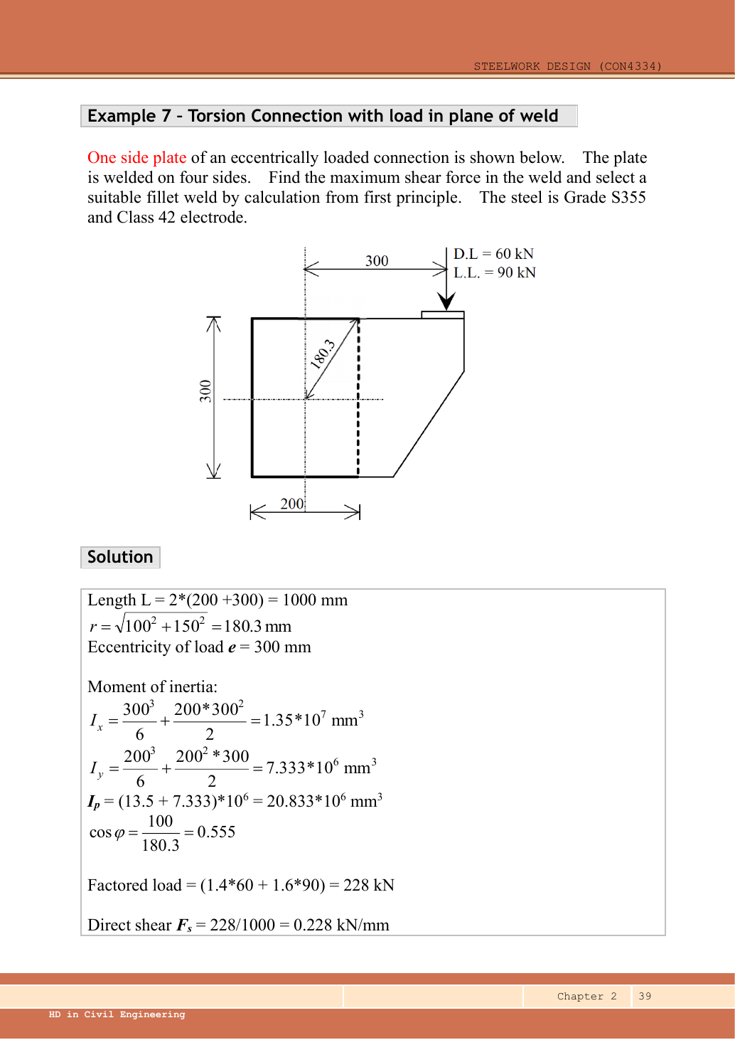
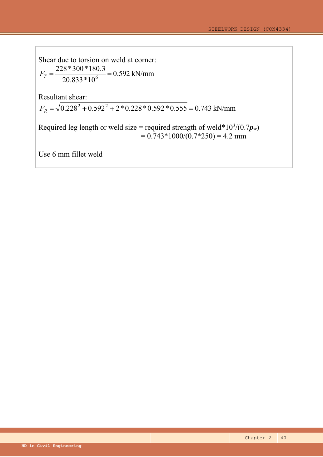
Read the diagram and collect the data
| Input | Origin |
|---|---|
| Given geometry | ,; four weld sides. Centre is at half width/height: , at a corner. |
| Given load arm | from group centroid, not from the right edge. |
| Given materials | S355/Class 42 → lookup , Table 9.2a. |
| Assumption | Uniform fillet size, rigid plate and line-weld elastic distribution, as in Ch 2 pp.35–37. |
Before calculating: recognition and strategy
Separate direct shear from torsional force caused by . Use the weld lines for centroid and inertia; the plate interior does not carry weld force. Derive line inertias with the parallel-axis rule. Then combine the horizontal and vertical force-per-length components at the right-hand corner, where vertical components add.
1. Geometry and factored force
Animation labA weld group is a set of lines
Supplement to the original lesson. Enable JavaScript to play, step through calculations and rotate 3D models. The following explanation remains readable offline.
- The centre is empty: resistance comes from the weld lines, not a solid plate filling the group.
- Use line lengths for centroid weighting. Line second moments have units ; add the parallel-axis terms.
- Direct force per length is . The eccentric moment adds tangential flow proportional to distance from the centroid.
- Combine signed components at every candidate corner, then compare the maximum with throat resistance per length.
2. Derive both line second moments
Simple explanation: Only the weld lines resist as weld
Imagine a wire rectangle: its empty middle is not more wire.
- Count only the weld runs actually shown.
- Use their total length and line second moments.
- Combine direct and torsional forces at the critical location.
Remember: Line second moments have units ; plate-area moments use .
About the horizontal centroidal axis: two vertical welds each contribute ; two horizontal welds each contribute . About the vertical axis reverse the roles.
Why is the unit ? Weld-line length () multiplied by distance squared () gives that unit. Do not substitute the second moment of area of a solid rectangular plate, , whose unit is .
Animation labA weld group is a set of lines
Supplement to the original lesson. Enable JavaScript to play, step through calculations and rotate 3D models. The following explanation remains readable offline.
- The centre is empty: resistance comes from the weld lines, not a solid plate filling the group.
- Use line lengths for centroid weighting. Line second moments have units ; add the parallel-axis terms.
- Direct force per length is . The eccentric moment adds tangential flow proportional to distance from the centroid.
- Combine signed components at every candidate corner, then compare the maximum with throat resistance per length.
3. Uniform direct shear per length
Animation labA weld group is a set of lines
Supplement to the original lesson. Enable JavaScript to play, step through calculations and rotate 3D models. The following explanation remains readable offline.
- The centre is empty: resistance comes from the weld lines, not a solid plate filling the group.
- Use line lengths for centroid weighting. Line second moments have units ; add the parallel-axis terms.
- Direct force per length is . The eccentric moment adds tangential flow proportional to distance from the centroid.
- Combine signed components at every candidate corner, then compare the maximum with throat resistance per length.
4. Torsional components at the critical corner
The source uses for the angle between the vertical direct shear and the tangential torsion force. The corner radius itself is not the force direction.
Animation labA weld group is a set of lines
Supplement to the original lesson. Enable JavaScript to play, step through calculations and rotate 3D models. The following explanation remains readable offline.
- The centre is empty: resistance comes from the weld lines, not a solid plate filling the group.
- Use line lengths for centroid weighting. Line second moments have units ; add the parallel-axis terms.
- Direct force per length is . The eccentric moment adds tangential flow proportional to distance from the centroid.
- Combine signed components at every candidate corner, then compare the maximum with throat resistance per length.
5. Add components and calculate the maximum
Simple explanation: Add arrows before taking the magnitude
Walking east and walking north do not point in the same direction.
- Choose signed horizontal and vertical directions.
- Add contributions along each direction separately.
- For perpendicular components, use the right-triangle resultant.
Remember: Check the corner where direct and torsional components reinforce each other.
The opposite column of weld has vertical components subtracting, hence a smaller resultant. The upper and lower right corners have the same maximum magnitude.
Animation labA weld group is a set of lines
Supplement to the original lesson. Enable JavaScript to play, step through calculations and rotate 3D models. The following explanation remains readable offline.
- The centre is empty: resistance comes from the weld lines, not a solid plate filling the group.
- Use line lengths for centroid weighting. Line second moments have units ; add the parallel-axis terms.
- Direct force per length is . The eccentric moment adds tangential flow proportional to distance from the centroid.
- Combine signed components at every candidate corner, then compare the maximum with throat resistance per length.
6. Size the fillet and check its resistance
Simple explanation: Why the weld throat is smaller than its leg
The shortest cut through the weld is thinner than the outside leg.
- For the stated equal-leg 90° fillet, throat is approximately 0.7 × leg.
- Multiply throat area by the matching weld design strength.
- For force per length, use a one-millimetre weld strip.
Remember: Choose strength from both the steel grade and electrode class.
The closed four-side weld is treated as the full line rectangle by the source method. This differs from separately terminated side welds with start/end deductions. The plate thickness is absent, so the numerical strength result is complete but minimum/maximum permitted leg size cannot be confirmed from Table 9.1/edge-thickness rules. The choice is the lecturer’s selection, conditional on those missing detailing inputs.
Animation labFrom fillet leg to effective throat
Supplement to the original lesson. Enable JavaScript to play, step through calculations and rotate 3D models. The following explanation remains readable offline.
- An equal-leg fillet between perpendicular plates has an approximately right-triangular section.
- For this geometry, throat . It is shorter than the leg.
- Effective resisting area = . With here, capacity per length is .
- Use the course end allowances, minimum size and length rules; increasing the geometric length alone does not resolve every detailing check.
Compact exam answer
,,,. ; torsion components vertical and 0.49248 horizontal kN/mm. . ; fillet supplies and passes weld strength. Plate-thickness detailing remains unverified because it is not given.
Mistakes to avoid
- The two dimensions mean different things: height and eccentricity.
- Use line inertia in , not solid-plate inertia in .
- The dashed right edge still belongs to the stated four-side weld.
- Do not certify minimum/maximum weld size without the plate thickness.
Procedure for an unfamiliar variant
- Identify every actual weld line and its load path.
- Find centroid, length and line inertias.
- Measure load eccentricity from the centroid.
- Calculate direct and torsional components and the critical resultant.
- Solve for leg size and check detailing separately.
Independent self-check
Try it yourself. Keep the same load and rectangle but move the load line through the weld centroid. Find required strength and leg by strength alone.
Reveal answer and reasoning
so torsion vanishes. . by strength alone. The actual selected leg is still controlled by minimum/detailing rules; a design cannot be adopted just from this strength result.
Animation labA weld group is a set of lines
Supplement to the original lesson. Enable JavaScript to play, step through calculations and rotate 3D models. The following explanation remains readable offline.
- The centre is empty: resistance comes from the weld lines, not a solid plate filling the group.
- Use line lengths for centroid weighting. Line second moments have units ; add the parallel-axis terms.
- Direct force per length is . The eccentric moment adds tangential flow proportional to distance from the centroid.
- Combine signed components at every candidate corner, then compare the maximum with throat resistance per length.
Connection example 8: flange welds carry moment, web welds carry shear
Open this example on its own page
Design the bracket welds for dead plus imposed load at from the support. The bracket is cut from a UB. The specified web-weld leg is half the flange-weld leg. Use S355 and Class 42 electrode.
Original source: LectureNotes/Ch 2_Connection.pdf — p. 41. Values tagged given are in the question or diagram; lookup values come from a named table; calculated values follow from the working; assumptions are stated explicitly.
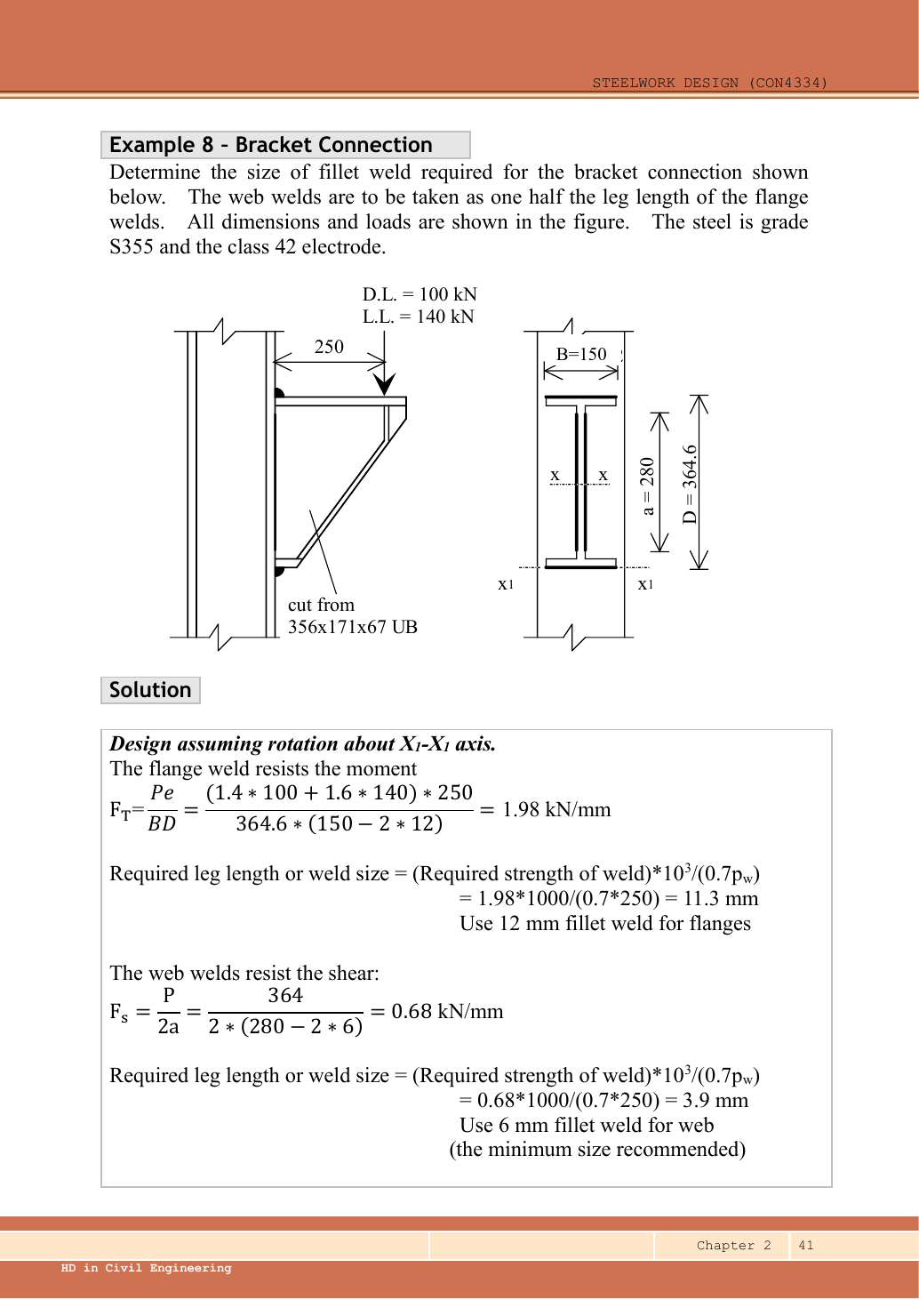
Read the diagram and collect the data
| Input | Origin |
|---|---|
| Given load | dead, imposed; downward arrow at from connection face. |
| Given weld geometry | across flange run; vertical arm; web run; all explicitly dimensioned. |
| Given size relationship | 。 |
| Lookup/model | . Rotate about at bottom flange; flange weld takes moment, two web welds take direct shear. This is the source’s simplified force allocation. |
Before calculating: recognition and strategy
Do not treat this as a rectangular in-plane torsion weld. The vertical load outside the supporting face produces flange tension and compression. Moment equilibrium gives tensile flange force . Divide that force by the effective flange weld length to get demand per millimetre. Because effective length depends on chosen leg, select a trial leg and verify it self-consistently.
1. Design force and force couple
Animation labSeparate the moment couple and shear
Supplement to the original lesson. Enable JavaScript to play, step through calculations and rotate 3D models. The following explanation remains readable offline.
- A simplified moment connection assigns different actions to different fastener groups.
- Opposite flange forces separated by z resist moment: .
- The web fasteners or welds carry the assigned vertical shear in this model.
- Flange force, web shear, plate bearing and detailing each need their specified checks.
2. Trial flange fillets
Simple explanation: How two flange forces make a moment
Two opposite forces form a turning pair, like two hands turning a wheel.
- Identify the separation between their actual force lines.
- Required force equals moment divided by that separation.
- Design the relevant flange group for that force.
Remember: The force-line separation is not automatically the overall section depth.
The source tries . The available run loses at its ends, leaving effective. Use the printed weld run , not the nominal section width.
This also solves the implicit inequality by a verified trial. Increasing improves throat but shortens effective length, so do not omit the recheck.
Animation labFrom fillet leg to effective throat
Supplement to the original lesson. Enable JavaScript to play, step through calculations and rotate 3D models. The following explanation remains readable offline.
- An equal-leg fillet between perpendicular plates has an approximately right-triangular section.
- For this geometry, throat . It is shorter than the leg.
- Effective resisting area = . With here, capacity per length is .
- Use the course end allowances, minimum size and length rules; increasing the geometric length alone does not resolve every detailing check.
3. Apply the required half-size rule and check shear
Simple explanation: Why the weld throat is smaller than its leg
The shortest cut through the weld is thinner than the outside leg.
- For the stated equal-leg 90° fillet, throat is approximately 0.7 × leg.
- Multiply throat area by the matching weld design strength.
- For force per length, use a one-millimetre weld strip.
Remember: Choose strength from both the steel grade and electrode class.
Even though strength alone needs only about , use to satisfy the given relationship to the flange weld.
Animation labFrom fillet leg to effective throat
Supplement to the original lesson. Enable JavaScript to play, step through calculations and rotate 3D models. The following explanation remains readable offline.
- An equal-leg fillet between perpendicular plates has an approximately right-triangular section.
- For this geometry, throat . It is shorter than the leg.
- Effective resisting area = . With here, capacity per length is .
- Use the course end allowances, minimum size and length rules; increasing the geometric length alone does not resolve every detailing check.
4. Check lengths and identify the remaining thickness condition
Simple explanation: Drawn length and useful length differ
The start and end of a weld are not credited as fully effective in this course model.
- Find the effective length required by strength.
- Add the specified end allowance to each separate run.
- Round up, then check minimum size, spacing and returns.
Remember: Strength alone does not prove a weld detail is acceptable.
The source dimensions describe weld runs on the cut bracket, not a licence to infer other fabrication details from scale. The supporting column thickness is not stated. The result therefore establishes flange/web weld strength and the size ratio; applicability of the thicker-part minimum-size rule to the support must be confirmed separately.
Animation labFrom fillet leg to effective throat
Supplement to the original lesson. Enable JavaScript to play, step through calculations and rotate 3D models. The following explanation remains readable offline.
- An equal-leg fillet between perpendicular plates has an approximately right-triangular section.
- For this geometry, throat . It is shorter than the leg.
- Effective resisting area = . With here, capacity per length is .
- Use the course end allowances, minimum size and length rules; increasing the geometric length alone does not resolve every detailing check.
Compact exam answer
,. About , flange force. flange weld has effective length and resistance. web welds each have effective length, combined resistance . Both pass and web leg is half flange leg. Support thickness for minimum weld-size verification is not supplied.
Mistakes to avoid
- The moment arm is ; the web run is . They are not interchangeable.
- Use two web welds, but the source’s tension-flange force is resisted by the specified flange run.
- Subtract using that run’s own leg size.
Procedure for an unfamiliar variant
- Identify the source pivot and the flange-force arm.
- Factor load and calculate moment/force couple.
- Try a flange leg, calculate its effective length and verify capacity.
- Apply the specified web/flange size relationship and check web shear.
- Check effective-length/detailing rules and state unprovided support data.
Independent self-check
Try it yourself. Keep the selected welds and increase the eccentricity to . What happens to the flange strength check?
Reveal answer and reasoning
Flange force becomes , greater than . The flange weld fails while the unchanged direct web shear remains and still passes.
Animation labSeparate the moment couple and shear
Supplement to the original lesson. Enable JavaScript to play, step through calculations and rotate 3D models. The following explanation remains readable offline.
- A simplified moment connection assigns different actions to different fastener groups.
- Opposite flange forces separated by z resist moment: .
- The web fasteners or welds carry the assigned vertical shear in this model.
- Flange force, web shear, plate bearing and detailing each need their specified checks.
Animation labA weld group is a set of lines
Supplement to the original lesson. Enable JavaScript to play, step through calculations and rotate 3D models. The following explanation remains readable offline.
- The centre is empty: resistance comes from the weld lines, not a solid plate filling the group.
- Use line lengths for centroid weighting. Line second moments have units ; add the parallel-axis terms.
- Direct force per length is . The eccentric moment adds tangential flow proportional to distance from the centroid.
- Combine signed components at every candidate corner, then compare the maximum with throat resistance per length.
Practise this chapter: tutorials, assignments and past-paper answers →