Connection example 1: single bolted unequal angle
Open “Animation lab” beside a teaching step for a visual explanation or a walkthrough of its original expressions. Models are illustrative; source answers remain unchanged.
← Read this lecture example beside its chapter concepts
Need a simpler picture? Open “Simple explanation” beside a difficult step. These optional notes do not replace the full solution.
Check a single S355 angle connected through its long leg to a plate by the stated two Grade 8.8 M20 bolts. Dead tension is ; imposed tension is . Check bolt shear, bolt/plate bearing and angle tension.
Original source: LectureNotes/Ch 2_Connection.pdf — p. 16, p. 17. Values tagged given are in the question or diagram; lookup values come from a named table; calculated values follow from the working; assumptions are stated explicitly.
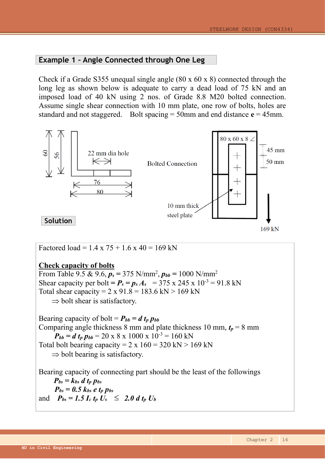
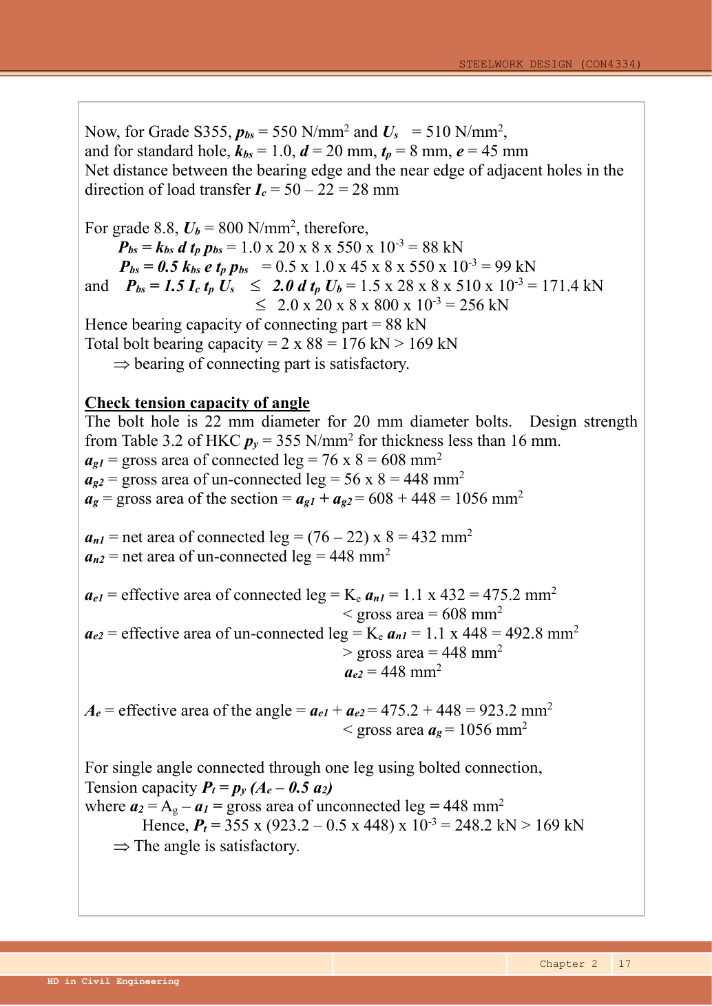
Read the diagram and collect the data
| Input | Value and exact source |
|---|---|
| Given loads | dead and imposed, question text; the downward arrow is the resulting tension direction. |
| Given geometry | Long leg ; short leg ; . The split dimensions and allocate half the heel thickness to each leg. |
| Given fasteners | Text specifies TWO M20 Grade 8.8 bolts; standard holes; pitch; end distance. |
| Given plate/model | supporting plate; one shear plane explicitly stated. |
| Lookup | Ch 2 p.3 M20 tensile stress area . Ch 2 pp.9–10 Grade 8.8: , , . S355: , , . Data File p.1, thickness : . |
Before calculating: recognition and strategy
This is concentric tension through one connected angle leg. The load crosses the angle-to-plate interface as bolt shear, presses on holes as bearing, and remains tension in the angle. Start with the factored force. Check each fastener mode, then the reduced angle tension resistance. Prerequisites: stress×area gives force; “net area” removes holes; a single-leg connection needs the specific unconnected-leg reduction.
1. Convert characteristic loads to one design force
is the ULS tensile demand in . Apply the course gravity factors once; the supplied loads are characteristic, not already ultimate.
Animation labFrom characteristic to design load
Supplement to the original lesson. Enable JavaScript to play, step through calculations and rotate 3D models. The following explanation remains readable offline.
- G is permanent load; Q is imposed load. A surface load and a line load also have different units.
- This illustration uses the course gravity case . Other combinations in the original text retain their own factors.
- For illustrative , change Q and watch each separate contribution.
- Do not carry this ULS total automatically into deflection. Follow the stated SLS load case.
2. Bolt shear across the single interface
Simple explanation: Count where the bolt can be sheared
The plate interfaces are the places trying to cut across the bolt.
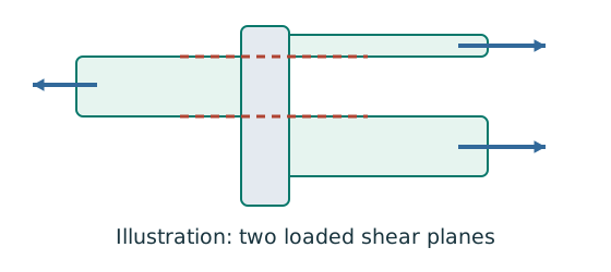
- Count actual loaded shear planes, not merely visible plates.
- Choose shank or threaded area for the plane concerned.
- Compare group resistance with the force that group transfers.
Remember: Bolts on opposite sides of a splice do not all act in parallel.
is the tensile stress area because no thread-free shear plane is guaranteed. There is one interface between the angle leg and the support plate, so no factor for double shear.
Animation labCount the bolt shear planes
Supplement to the original lesson. Enable JavaScript to play, step through calculations and rotate 3D models. The following explanation remains readable offline.
- Load must cross an interface between the connected plates.
- A lap joint gives one shear plane through a bolt.
- A symmetric double-cover joint may provide two shear planes. Count load-transfer interfaces, not just visible plates.
- Use the source’s area and shear strength. Then check bearing, plate resistance and detailing separately.
3. Bearing of the bolts
Simple explanation: The bolt can crush or tear the plate
A strong bolt can still push through a weak hole edge.
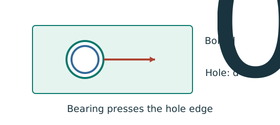
- Check the bolt and each connected plate’s bearing bounds.
- Use nominal bolt diameter for bearing; hole size for removed material.
- The smallest applicable resistance controls.
Remember: A short end distance may govern even when bolt shear passes.
Use the thinner connected thickness : the angle leg governs. is the bolt diameter, not the hole.
Animation labBearing and the remaining ligament
Supplement to the original lesson. Enable JavaScript to play, step through calculations and rotate 3D models. The following explanation remains readable offline.
- Force transfers through contact between bolt and connected plate.
- The plate around the hole carries bearing stress. Bolt bearing and plate bearing are separate checks.
- A short ligament can tear out towards the end. The direction of force determines the relevant edge.
- Evaluate every specified bearing and ligament bound for each layer and retain the smallest applicable resistance.
4. Bearing and ligament resistance of the angle leg
The dimension is centre-to-centre pitch along tension. Subtract one full hole diameter to get the clear inter-hole ligament . The dimension is end distance from end to nearest bolt centre.
Plate bearing is closer to its limit than bolt shear: utilisation. This is why the larger bolt-bearing value cannot be used as the joint’s governing resistance.
Animation labBearing and the remaining ligament
Supplement to the original lesson. Enable JavaScript to play, step through calculations and rotate 3D models. The following explanation remains readable offline.
- Force transfers through contact between bolt and connected plate.
- The plate around the hole carries bearing stress. Bolt bearing and plate bearing are separate checks.
- A short ligament can tear out towards the end. The direction of force determines the relevant edge.
- Evaluate every specified bearing and ligament bound for each layer and retain the smallest applicable resistance.
5. Effective angle area and single-leg reduction
Simple explanation: One connected leg does not load both legs equally
The connected leg receives the pull first; the other leg receives it through the angle.
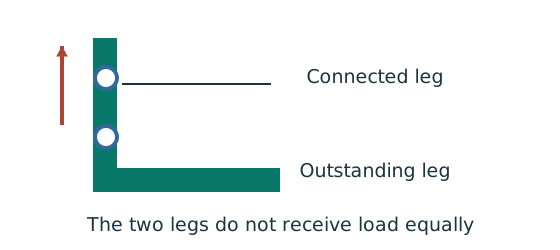
- Identify connected and outstanding legs from the drawing.
- Use the relevant bolted or welded angle rule.
- Keep the lecturer’s area convention consistent.
Remember: Bolted and welded reduction expressions are not the same rule.
Use the lecturer’s rectangular leg-area approximation. The heel is shared: connected leg width ; unconnected width . A transverse fracture line crosses one hole, not both bolts arranged along the member. Apply separately to each leg and cap each at its own gross area.
The factor belongs specifically to a single bolted angle connected through one leg (Ch 2 p.14). It is not a generic reduction for all tension members.
Animation labWhy a connected angle leg matters
Supplement to the original lesson. Enable JavaScript to play, step through calculations and rotate 3D models. The following explanation remains readable offline.
- Locate the connected leg, outstanding leg and centroid before using the table.
- Only the connected leg directly receives the fastener force.
- The outstanding area may not become equally effective at the same section; this motivates the effective-area rule.
- Bolted, welded, single-angle and double-angle details can have different rules. Preserve the formula attached to the original case.
6. State the governing result and the scope
For the requested resistance checks, the minimum is plate bearing , above . The angle tension check also passes. Units close correctly: stress× gives before dividing by .
The pitch equals and is less than . The end distance exceeds both supplied M20 minimum values ( or ). The transverse edge distances are not fully dimensioned in this example, so these observations do not prove that the entire arrangement has been verified.
Animation labFollow the calculation sequence
Supplement to the original lesson. Enable JavaScript to play, step through calculations and rotate 3D models. The following explanation remains readable offline.
- Locate the load, supports, connection geometry and any stated assumptions.
- Keep given values, table lookups and calculated values distinct; reconcile their units.
- The calculation player steps through the existing expressions in their original order.
- Compare demand with resistance or the relevant limit. Keep missing inputs and conditional conclusions explicit.
Compact exam answer
. Two bolts in single shear: ; bolt bearing ; angle bearing . ; single angle . All required resistances exceed the demand. Plate bearing governs, using the two-bolt model specified by the question.
Mistakes to avoid
- Do not multiply by two for shear planes; the given joint is single shear.
- Subtract for a hole, use for bearing.
- Do not multiply the unconnected gross leg area by without its gross-area cap.
- Do not silently replace the written two bolts with four based on the inconsistent sketch.
Procedure for an unfamiliar variant
- Read the written bolt count and the interface geometry; reconcile any discrepancy.
- Factor characteristic loads and distribute concentric load to the bolts.
- Check shear, bolt bearing and all connected-part bounds.
- Compute gross/net/effective leg areas and the correct single/double connection reduction.
- Compare each complete load path with the same demand and name the governing one.
Independent self-check
Try it yourself. Keep the geometry but increase imposed load to . Does the connection still pass the calculated strength checks?
Hint
Recalculate demand only; the capacities do not change when geometry and materials stay the same.
Reveal answer and reasoning
New . Plate bearing and bolt shear are both inadequate; angle tension still passes. A stronger angle alone would not fix the fastener path.
Animation labCount the bolt shear planes
Supplement to the original lesson. Enable JavaScript to play, step through calculations and rotate 3D models. The following explanation remains readable offline.
- Load must cross an interface between the connected plates.
- A lap joint gives one shear plane through a bolt.
- A symmetric double-cover joint may provide two shear planes. Count load-transfer interfaces, not just visible plates.
- Use the source’s area and shear strength. Then check bearing, plate resistance and detailing separately.