Foundations: understand the question before using a formula
Open “Animation lab” beside a teaching step for a visual explanation or a walkthrough of its original expressions. Models are illustrative; source answers remain unchanged.
Need a simpler picture? Open “Simple explanation” beside a difficult step. These optional notes do not replace the full solution.
You do not need to remember a whole lecture before starting a question. Learn to trace the load, write equilibrium, choose the relevant failure check, and keep units consistent. This chapter supplies the mathematics and mechanics used by every worked solution.
1. Units, powers and a calculator
Simple explanation: Keep the units on the same scale
Changing units is like changing the ruler, not the object.
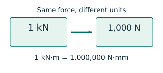
- ; .
- Area needs two length conversions; inertia needs four.
- Convert before substituting, then check the final unit.
Remember: A kN·m moment becomes 1,000,000 N·mm, not 1,000.
A force is a push or pull. Its unit is the newton (). A kilonewton is . A bending moment is force × perpendicular distance, so its unit is or . Stress is force divided by area: , also called . A section property is geometry, not a force.
| Quantity | Conversion | Why the power matters |
|---|---|---|
| Length | ; | Convert length before squaring or cubing. |
| Area | 。 | |
| Section modulus | Used in moment capacity or . | |
| Second moment of area | Used in and deflection. | |
| Moment | 。 | |
| Line load | Both numerator and denominator divide by . | |
| Area load | Width converts a floor load into a beam load. |
Work with and for beam reactions and moments. Switch to and for stress, strength and deflection, because and are quoted in . Write the conversion on the same line as the substitution.
On a calculator, brackets keep the whole denominator inside the square root: enter the equivalent of , not . A fourth root can be entered as a power of . To calculate , square the ratio first, evaluate the square bracket, take the fourth root, then take the reciprocal. Retain at least four significant figures before the final comparison.
Try it yourself. Convert and into mm units.
Reveal answer and reasoning
。。
Animation labUnits and powers
Supplement to the original lesson. Enable JavaScript to play, step through calculations and rotate 3D models. The following explanation remains readable offline.
- Force, length and stress must use compatible units before substitution.
- . An area has two length factors, so .
- A section modulus has ; second moment of area has . Use and for cm to mm.
- . Divide by to express that moment in .
Animation labUnits and powers
Supplement to the original lesson. Enable JavaScript to play, step through calculations and rotate 3D models. The following explanation remains readable offline.
- Force, length and stress must use compatible units before substitution.
- . An area has two length factors, so .
- A section modulus has ; second moment of area has . Use and for cm to mm.
- . Divide by to express that moment in .
2. Rearrangement and interpolation
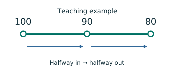
Simple explanation: A value between two table rows
Move the same fraction of the way across both number ranges.
- Choose the correct table, curve and strength column first.
- Find how far your input lies between the two rows.
- Apply that fraction to the change between their answers.
Remember: Teaching example: halfway between outputs 100 and 80 gives 90.
An equation balances two equal quantities. Whatever operation you apply to one side must also be applied to the other. To find required area from , divide both sides by : . Capacity and demand must use the same force unit.
To select a number of bolts, calculate n ≥ P/(capacity of one bolt) and round up to a whole number. To check an existing design, do not round a failed ratio down to . A utilisation of exceeds the limit even if a two-decimal display looks close.
Interpolation means finding a value between two tabulated points on an assumed straight line. It is not permission to use the wrong steel-grade column or buckling curve. First select those correctly. Let fall between and with tabulated values and . The fraction of the interval is .
Invented arithmetic demonstration: if a table gives strength at slenderness 70 and at 80, then at 74, and strength = . This is an explanation of interpolation, not a course-code lookup.
Try it yourself. Using that invented table, find the value at .
Reveal answer and reasoning
; strength . It lies between and .
Animation labInterpolate between two table rows
Supplement to the original lesson. Enable JavaScript to play, step through calculations and rotate 3D models. The following explanation remains readable offline.
- Select the correct curve, grade and strength column before choosing the two bracketing rows.
- . The slider shows the fraction between the two endpoints.
- . A decreasing table needs a negative change in y.
- The example uses illustrative outputs 100 and 80. At the result is 90; do not extrapolate missing rows.
Animation labRearrange a capacity equation
Supplement to the original lesson. Enable JavaScript to play, step through calculations and rotate 3D models. The following explanation remains readable offline.
- For , P is force, p is stress and A is area. Here we want A.
- Divide both sides by the same non-zero stress p.
- The p on the right cancels, leaving .
- gives . This is required area, not a selected section or a complete design check.
3. Read a structure as a load path
Simple explanation: Why reactions balance the loads
Think of a seesaw that must neither fall nor turn.
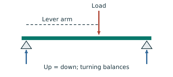
- Upward and downward forces must balance.
- Take moments about a support to eliminate its reaction.
- Use perpendicular distance from the point to the force line.
Remember: A lateral restraint is not automatically a vertical support.
A floor slab carries an area load. It passes reactions to secondary beams; secondary beams pass reactions to primary beams; primary beams pass reactions to columns; columns pass compression to foundations. A beam end reaction is an upward force on that beam and an equal downward force on the member supporting it. Drawing both arrows on the same isolated member would double-count the connection force.
A free-body diagram isolates one member and replaces its surroundings with support reactions. A pin resists translation but permits rotation. A roller allows movement along its supporting surface and supplies one reaction normal to that surface. A fixed support restrains rotation and can supply a moment. A lateral restraint stops sideways movement of the relevant flange; it does not automatically create a vertical support in the beam analysis.
For the course simply supported beam, the pin and roller at the ends support vertical loads. For a symmetric load arrangement, symmetry gives equal vertical reactions. Otherwise use the two equilibrium equations below. Take anticlockwise moments as positive for this derivation; a different consistent convention gives the same physical answers.
Here is support spacing (), is a point load (), is its distance from A (), and is a uniform line load () over the full span. A UDL is replaced by its total at the centre of its loaded length only when taking overall equilibrium. Keep the distribution when finding shear or moment along the member.
A tributary width is the strip of slab whose load reaches a beam. For a one-way slab with equal beam spacing , an interior beam takes from each side, total ; an edge beam usually takes from one side. Verify the slab span arrows and supports. Do not take a span dimension as a tributary width just because it is the nearest printed number.
Try it yourself. Invented beam: ; a load at from A; over the full span. Find reactions.
Hint
Take moments about A so its unknown reaction has zero lever arm.
Reveal answer and reasoning
. . The two reactions sum to , equal to total downward load.
Animation labBalance reactions and moments
Supplement to the original lesson. Enable JavaScript to play, step through calculations and rotate 3D models. The following explanation remains readable offline.
- This demonstrator is a simply supported 6 m beam with a 60 kN point load; it is not the page’s original loading diagram.
- . Moving the load towards B increases .
- . The two upward reactions must sum to P.
- With the load at midspan, . End couples, UDLs and overhangs require their own equilibrium terms.
Animation labFollow the floor load in 3D
Supplement to the original lesson. Enable JavaScript to play, step through calculations and rotate 3D models. The following explanation remains readable offline.
- The floor carries pressure in . The highlighted strip belongs to one secondary beam.
- Multiply pressure by tributary width: . The illustration uses .
- A primary beam receives the secondary beam reaction at their connection, not a new full-span UDL.
- Trace reactions down to columns and foundations. Count each loaded area once.
4. Shear force, bending moment and deflection
Simple explanation: What shear is trying to do
Imagine cutting the beam: shear stops the two cut faces sliding past each other.
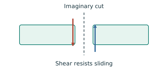
- Find the design shear from the load analysis.
- Use the section’s applicable shear area and strength.
- Compare demand with resistance in the same force units.
Remember: The web usually carries much of the vertical shear in an I-section.
Shear is the internal transverse force needed to keep either part of a cut beam in equilibrium. Bending moment is the internal turning effect at that cut. Deflection is the displacement of the beam from its unloaded position. Capacity answers “how much can it resist?”; demand answers “what does the loading require?”
Under a UDL the shear diagram is a straight sloping line and the moment diagram is a parabola. A point load causes a vertical jump in shear, while moment stays continuous. An applied couple causes a jump in the moment diagram. Between point loads the maximum or minimum moment occurs where ; also check supports, load points and overhang roots. A point load need not be at the position of maximum moment.
These shortcuts assume a simply supported beam and the stated load position. For an off-centre point load or an overhang, start with equilibrium. Under linear elastic behaviour, results of separate load cases can be added at the same position (superposition). Adding maxima at different positions is not generally an exact maximum.
For a prismatic simply supported beam with constant and :
is the course Young’s modulus: material stiffness. is the second moment of area about the bending axis in : geometric stiffness. Use unfactored imposed load for the course’s usual beam deflection checks. A load factor increases design demand for ULS; it does not increase the physical stiffness .
Try it yourself. A simply supported beam has and . What are its maximum shear and moment?
Reveal answer and reasoning
. . The moment has one extra length factor, so it cannot have units .
Animation labBalance reactions and moments
Supplement to the original lesson. Enable JavaScript to play, step through calculations and rotate 3D models. The following explanation remains readable offline.
- This demonstrator is a simply supported 6 m beam with a 60 kN point load; it is not the page’s original loading diagram.
- . Moving the load towards B increases .
- . The two upward reactions must sum to P.
- With the load at midspan, . End couples, UDLs and overhangs require their own equilibrium terms.
Animation labBuild the shear and moment diagrams
Supplement to the original lesson. Enable JavaScript to play, step through calculations and rotate 3D models. The following explanation remains readable offline.
- For the illustrative 60 kN point load on a 6 m simply supported beam, balance the reactions before making a cut.
- and before the point load. Moment grows linearly.
- Shear jumps down by P. To its right, and .
- For this case, moment is continuous and returns to zero at B. A concentrated applied couple instead creates a moment jump.
5. Steel, stiffness, strength and ductility
Source: Chapter 1 pp. 2–3; L1 slides 3 and 10. Steel is mainly iron with small alloying additions. The course lists iron about , carbon up to , manganese up to , silicon –, and sulphur/phosphorus each up to . More carbon generally raises strength but reduces ductility and weldability, explaining the limited carbon content in structural steel.
Yield strength is the stress at which significant permanent deformation begins. Stiffness is resistance to elastic deformation; a higher steel grade does not by itself give a higher course value of . Ductility is the ability to deform substantially before fracture. Weldability is the ability to form satisfactory welded joints using suitable procedures. A design can be strong enough and still deflect too much.
The course uses S275, S355 and S460 for BS EN steels and describes Q235, Q345, Q390 and Q420 for Chinese-standard steels. The grade label is not automatically the design strength for every thickness. Use the relevant material table and thickness interval.
Animation labElasticity, yielding and ductility
Supplement to the original lesson. Enable JavaScript to play, step through calculations and rotate 3D models. The following explanation remains readable offline.
- Stress is force divided by area. Strain measures change in length relative to original length.
- Before yielding, stress is approximately . E controls the elastic slope.
- Further strain includes permanent deformation. Higher yield strength does not by itself increase E.
- Strength, stiffness and ductility answer different questions. This schematic is not a measured stress–strain curve.
6. Fatigue under repeated loading
Source: Chapter 1 pp. 2 and 14. Fatigue is progressive crack growth under repeated stress changes. Typical course examples are crane girders and bridges. It differs from one excessive static load: many repetitions can grow a crack even when one application appears harmless. Avoid abrupt changes in section and local stress concentrations in details. The notes say ordinary wind fluctuations generally do not require fatigue design unless numerous stress fluctuations arise; use the question’s stated loading regime.
Exam script: “Fatigue is failure caused by progressive crack growth under fluctuating stress. Avoid abrupt section changes and stress concentrations, and detail welded connections appropriately.”
Animation labRepeated loading grows a crack
Supplement to the original lesson. Enable JavaScript to play, step through calculations and rotate 3D models. The following explanation remains readable offline.
- A notch or abrupt detail can concentrate stress near the connection.
- Many load cycles can initiate a crack even when one application does not cause static failure.
- The illustrative crack length increases with the animation stages. It is not a fatigue-life calculation.
- Use the specified fatigue method and detail category. Avoid abrupt changes and identify whether repeated loading is relevant.
7. Corrosion protection
Source: Chapter 1 p.2. Corrosion removes steel and reduces effective section thickness. Paint and metallic coatings separate the steel from the environment. Zinc or aluminium coatings improve corrosion/abrasion resistance in the course discussion. Cathodic protection is described for structures continuously immersed in water. Weathering steel forms a protective oxide layer because of its alloy composition; it is a material choice with environmental applicability, not a paint coating.
Exam script for two methods: “Apply a protective paint or zinc coating to isolate the steel from corrosive exposure. For continuously immersed structures, use cathodic protection to reduce electrochemical corrosion.” Give two distinct methods and a short mechanism, rather than two brand names for paint.
Animation labHow corrosion protection works
Supplement to the original lesson. Enable JavaScript to play, step through calculations and rotate 3D models. The following explanation remains readable offline.
- Corrosion can consume steel and reduce its effective thickness.
- Paint and metallic coatings protect the exposed surface; coating integrity matters.
- Edges, damaged coatings and water-trapping details deserve attention. The model shows layers schematically.
- Weathering steel and cathodic protection have specific environmental applications; they are not universal substitutes for paint.
8. Fire protection: learn the sketch
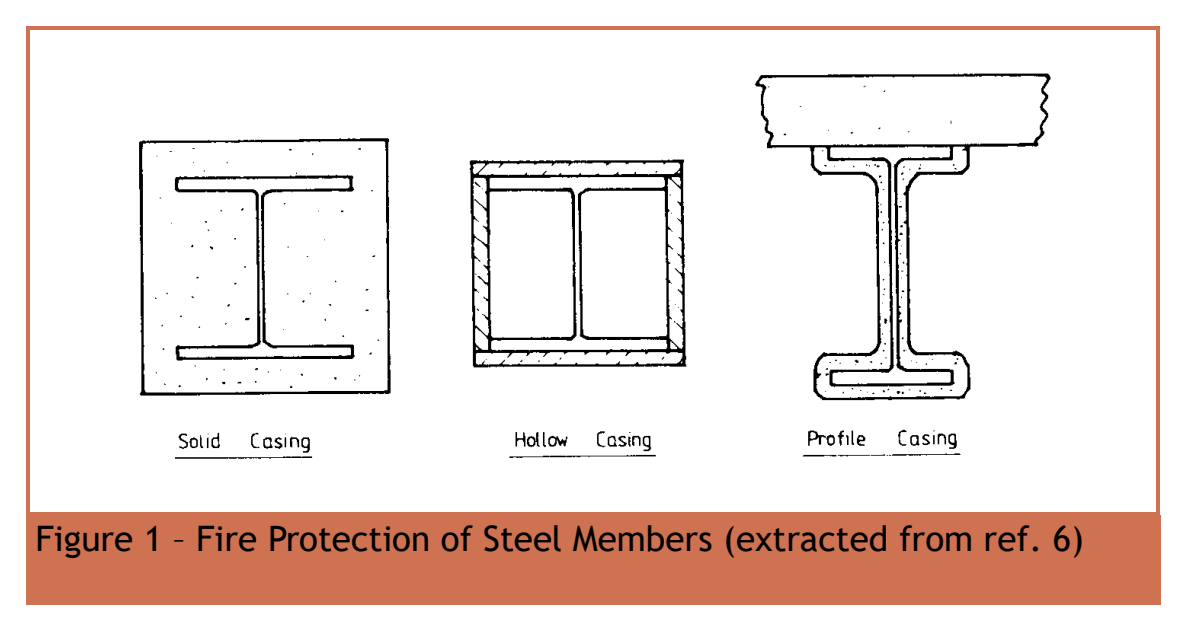
Source: Chapter 1 p.3. Structural steel loses strength as temperature rises. Fire protection delays heating of the load-bearing section. In the original sketch, solid casing fills the rectangle around the I section; hollow casing forms a box with an air space; profile casing follows the steel outline. For a “sketch two methods” answer, draw the I section clearly inside each protection outline and label the protection. The supplied figure does not specify a material thickness or resistance period, so do not invent one.
Try it yourself. Does a hollow fire-protection casing mean the structural steel member itself must be a hollow section?
Reveal answer and reasoning
No. The source figure shows an I section inside a hollow protective enclosure. Distinguish the steel shape from the protection shape.
Animation labSee the fire-protection enclosure
Supplement to the original lesson. Enable JavaScript to play, step through calculations and rotate 3D models. The following explanation remains readable offline.
- Steel loses strength as it heats. Protection aims to delay heat reaching the section.
- Solid casing fills the enclosure around the I-section.
- A hollow enclosure surrounds the section while leaving an air space.
- Profile casing follows the section outline. The supplied sketch does not determine protection thickness or fire duration.
9. Section shapes, axes and the section designation
Simple explanation: Why I, Z and S are different
The same section has different numbers for different jobs.
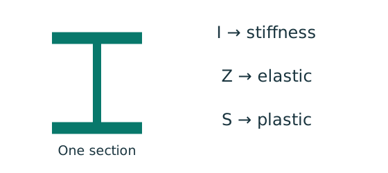
- I describes how area is spread: it affects elastic stiffness.
- Z is the elastic section modulus; S is the plastic section modulus.
- Choose the property, axis and units required by the formula.
Remember: Do not substitute S for Z merely because it is larger.
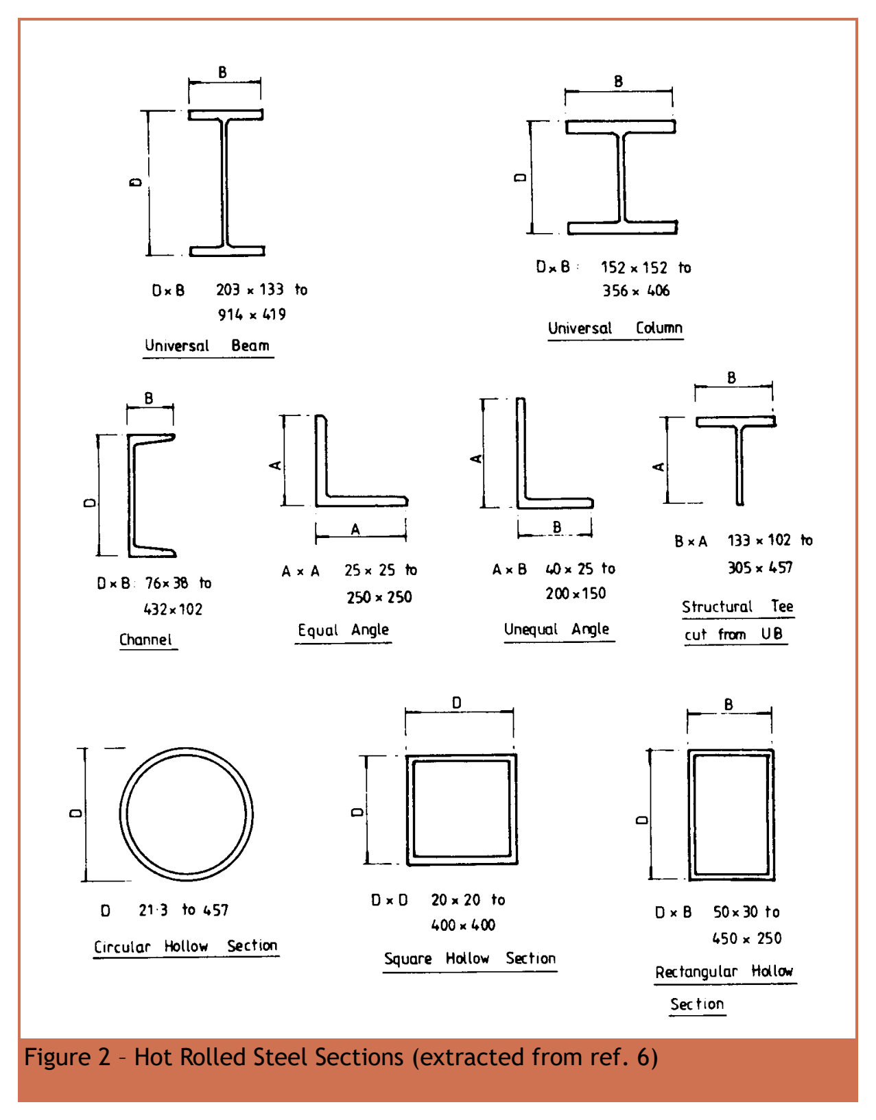
UB means Universal Beam; its deeper shape efficiently resists bending about its major axis. UC means Universal Column; its broad flanges suit compression and biaxial resistance. Channels and angles are common in bracing, trusses and compound members. A structural tee can be cut from a UB or UC. CHS, SHS and RHS mean circular, square and rectangular hollow sections. In these course calculations is the major cross-section axis and is the minor axis.
A designation such as UB gives nominal size and mass per unit length. It does not say its actual depth is exactly , flange width exactly , or thickness . Look up the actual dimensions and properties in the row with the complete designation. With , produces self-weight.
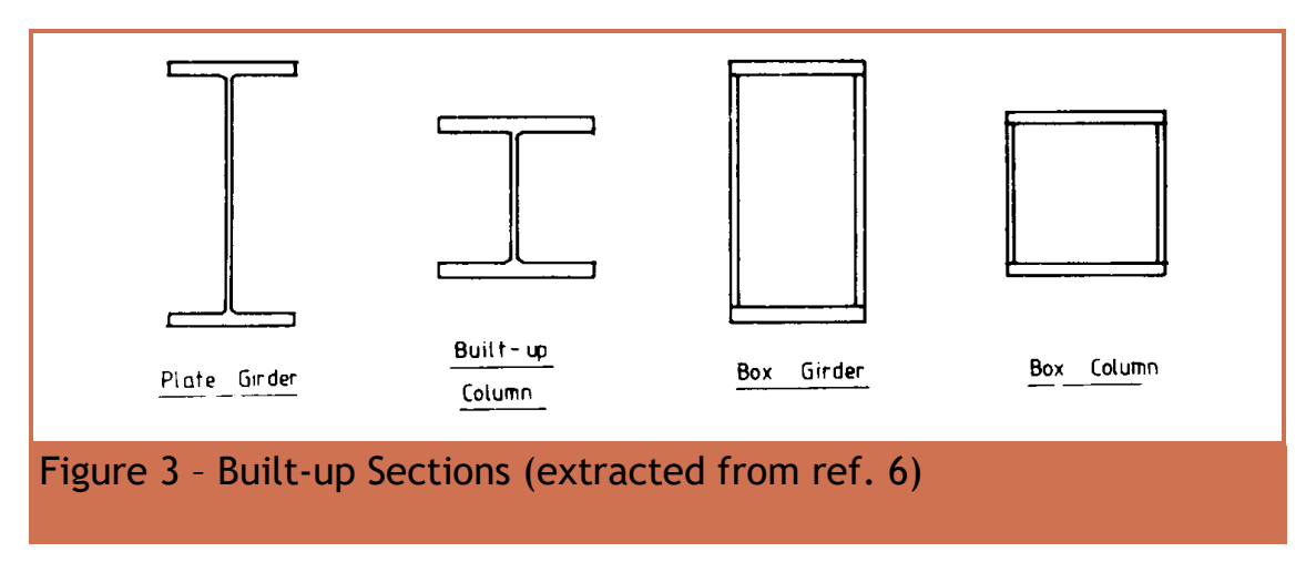
Built-up sections are fabricated from plates welded into an I, H or box. In a sketch show the separate web/flange plates or box walls and indicate their welded joints. A compound section combines rolled members or adds cover plates; the original examples include strengthened beams, crane girders, battened and laced columns.
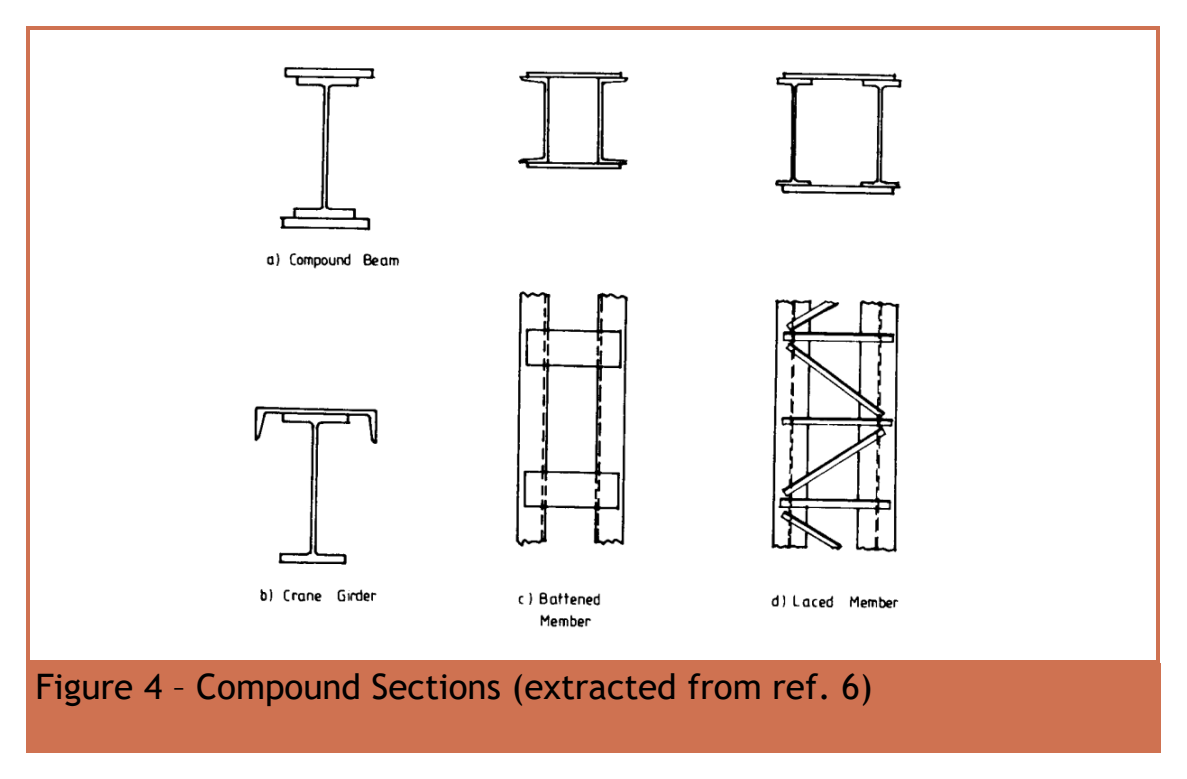
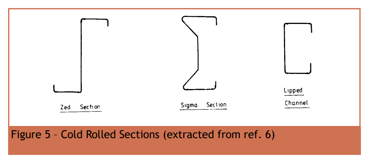
Cold-formed sections are bent from thin sheet, often used as purlins and sheeting rails. Do not apply the UB section formulas automatically to these thin-walled shapes. For an exam asking four hot-rolled shapes, use UB, UC, channel and angle, with recognisable labelled cross sections.
Animation labExplore section geometry and axes
Supplement to the original lesson. Enable JavaScript to play, step through calculations and rotate 3D models. The following explanation remains readable offline.
- The flanges are the wide plates; the web connects them. Rotate the I-section to see both.
- The same section has different stiffness and resistance about its two principal axes.
- I controls elastic curvature; is elastic section modulus. Plastic modulus S comes from plastic stress blocks.
- Nominal section labels are not every actual dimension. Keep the row, axis and units together.
10. ULS and SLS
Simple explanation: Strong enough and stiff enough are two questions
A shelf can avoid breaking yet still sag too much.
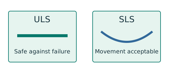
- ULS checks safety against the relevant failure modes.
- SLS checks the specified everyday-use limit.
- Use the load case required for each check.
Remember: Passing bending resistance does not prove deflection passes.
Source: Chapter 1 p.7, Table 2.1 extract. A limit state is a condition beyond which a structure no longer meets a requirement. Ultimate limit state (ULS) concerns collapse or irreparable damage: yielding, rupture, buckling, mechanism formation, overturning, sliding, uplift, fire, brittle fracture and fatigue. Serviceability limit state (SLS) concerns use: excessive deflection, vibration, wind-induced oscillation and durability.
The design process applies load factors to characteristic loads, calculates their effects, and compares those effects with design resistance. A higher factor for imposed load reflects greater uncertainty/variation in that action. Material safety treatment is already embodied in the supplied design-strength values; do not add an unrelated Eurocode material factor to these course capacities.
Try it yourself. A beam has adequate strength but cracks its plaster finish through excessive movement. Which check has failed?
Reveal answer and reasoning
Serviceability, specifically deflection. Passing ULS does not establish SLS adequacy.
Animation labTwo different design questions
Supplement to the original lesson. Enable JavaScript to play, step through calculations and rotate 3D models. The following explanation remains readable offline.
- ULS compares factored actions with the applicable resistance to yielding, rupture or instability.
- SLS checks movement, vibration or another specified use requirement.
- A beam can be strong enough but deflect too much. The two checks need their own loads and denominators.
- A resistance pass cannot stand in for a serviceability pass. Complete all requested checks.
11. Which loads and factors belong in a calculation?
Simple explanation: Why dead and imposed loads stay separate
Keep two shopping baskets until their different multipliers are applied.
- Put self-weight and permanent finishes in the dead-load basket.
- Put the specified use load in the imposed-load basket.
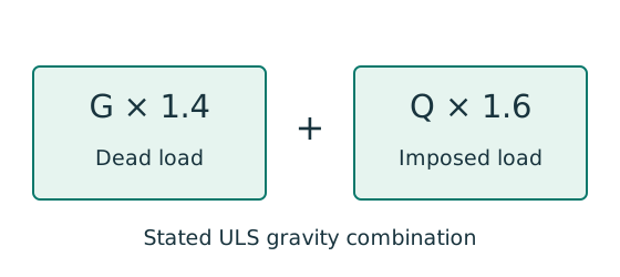
- For this course’s stated gravity combination: .
Remember: That ULS combination is not the imposed-load deflection load.
Source: Chapter 1 pp.8–9 and 13–14; Data File p.1 onward. is characteristic dead load (permanent self-weight/finishes); is characteristic imposed load (use/occupancy); is wind load. The principal adverse combinations taught are:
These compact forms assume adverse actions in the stated combination. The original Table 4.2 distinguishes beneficial actions: dead load resisting uplift or overturning uses , and favourable imposed load may be omitted. Table 4.4 also contains crane, earth/water, temperature, accidental and construction cases. Read that exact row if one is specified; do not extrapolate / to every action.
An ultimate/factored/design load has already been factored. Do not multiply it by or again. If a question gives characteristic dead and imposed loads separately, factor them once. If self-weight is explicitly included, do not add it again. Otherwise mass per metre × gives a dead line load.
Try it yourself. Invented slab: concrete at , finishes and imposed load . Find factored floor intensity.
Reveal answer and reasoning
Concrete: . Dead total . .
Animation labFrom characteristic to design load
Supplement to the original lesson. Enable JavaScript to play, step through calculations and rotate 3D models. The following explanation remains readable offline.
- G is permanent load; Q is imposed load. A surface load and a line load also have different units.
- This illustration uses the course gravity case . Other combinations in the original text retain their own factors.
- For illustrative , change Q and watch each separate contribution.
- Do not carry this ULS total automatically into deflection. Follow the stated SLS load case.
Animation labFrom characteristic to design load
Supplement to the original lesson. Enable JavaScript to play, step through calculations and rotate 3D models. The following explanation remains readable offline.
- G is permanent load; Q is imposed load. A surface load and a line load also have different units.
- This illustration uses the course gravity case . Other combinations in the original text retain their own factors.
- For illustrative , change Q and watch each separate contribution.
- Do not carry this ULS total automatically into deflection. Follow the stated SLS load case.
12. Simple, continuous and semi-continuous construction
Source: Chapter 1 p.10. Simple design idealises beam joints as pins, so a beam end does not develop a continuity moment. A bracing system or rigid core carries lateral actions. Nominal eccentricity of a vertical beam reaction can still bend the supporting column; “pinned beam connection” does not mean “column has zero moment”.
Continuous design uses connections with sufficient stiffness/strength for the frame analysis and transfers moments through joints. Semi-continuous design explicitly models intermediate joint stiffness and strength, based on test evidence or calibrated analysis. It is a stated theory topic here, not a licence to assume an arbitrary amount of fixity.
Animation labRestraints, sway and imperfections
Supplement to the original lesson. Enable JavaScript to play, step through calculations and rotate 3D models. The following explanation remains readable offline.
- A frame needs a defined path for horizontal force as well as gravity.
- Pinned joints alone do not provide frame moment resistance; sway restraint needs a real structural system.
- Diagonal bracing carries horizontal action through axial forces. This sketch does not assign a numerical frame classification.
- Use the specified imperfection/notional-force model and critical-load criteria. Avoid counting alternative imperfection models twice.
13. and : why geometry changes force effects
Simple explanation: Moving sideways gives the load a new lever arm
Once a compressed member moves sideways, the same compression creates extra moment.
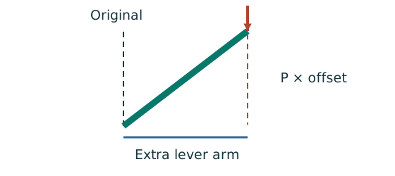
- P–Δ concerns overall frame or storey movement.
- P–δ concerns bowing relative to the member’s end line.
- Amplify only the first-order moments specified by the method.
Remember: Do not amplify a moment that the question already gives as amplified.
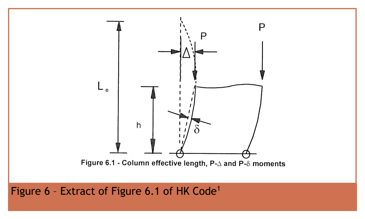
First-order analysis calculates equilibrium on the original undeformed geometry. If axial compression acts through a displaced point, it creates an extra moment: . is associated with frame sway/global displacement; with local member curvature. Identify which deformation appears in a sketch before naming the effect.
Second-order -only analysis considers the displaced frame but leaves local member bowing to be allowed for separately. Second-order analysis includes frame deformation, member bowing/stiffness change and imperfections. Advanced analysis also includes material yielding. The notes allow first-order results to be used with the specified effective-length and moment-amplification design checks; do not apply amplification twice to moments already stated to include it.
Exam script: “The analysis establishes equilibrium in the deformed position, including additional moments from axial forces acting through frame sway and member bow . Frame/member imperfections and stiffness changes are included in the second-order model.”
Animation labSeparate P–Δ from P–δ
Supplement to the original lesson. Enable JavaScript to play, step through calculations and rotate 3D models. The following explanation remains readable offline.
- The dashed line marks the original frame position; axial compression acts downwards.
- Global displacement Δ creates the additional moment PΔ.
- Local displacement δ is measured from the line joining the displaced ends, and adds Pδ.
- Follow the original analysis route. Do not amplify an already amplified moment or confuse critical-load factor with member slenderness.
14. Imperfections and notional horizontal force
Source: Chapter 1 pp.12–13 and L1 slide 8. Real frames are not perfectly plumb and members are not perfectly straight. The course equivalent global geometric imperfection is . An alternative uses a notional horizontal force equal to of the relevant factored vertical loading. These represent an imperfection model, not a new gravity load.
The initial member bow depends on its buckling curve: the Table 6.1 extract lists , , , and for curves , , , and respectively. Use the applicable method. The effective-length/moment-amplification design approach already represents relevant imperfection effects; do not independently add fictitious bow moment without checking the analysis model.
Animation labRestraints, sway and imperfections
Supplement to the original lesson. Enable JavaScript to play, step through calculations and rotate 3D models. The following explanation remains readable offline.
- A frame needs a defined path for horizontal force as well as gravity.
- Pinned joints alone do not provide frame moment resistance; sway restraint needs a real structural system.
- Diagonal bracing carries horizontal action through axial forces. This sketch does not assign a numerical frame classification.
- Use the specified imperfection/notional-force model and critical-load criteria. Avoid counting alternative imperfection models twice.
15. Strength, overall stability and robustness
Source: Chapter 1 pp.14–15. Strength checks compare member/connection demand with resistance. Overall stability prevents overturning, sliding, uplift or uncontrolled sway. Bracing, moment-resisting joints, shear walls and cores can supply lateral resistance. Robustness limits the spread of accidental local damage into disproportionate collapse.
The source’s robustness measures include vertical and horizontal tension ties, resistance to minimum horizontal loads, alternative load paths after removal of a vertical element, and design of key elements. In an exam explanation, connect the measure to the failure it prevents: a tie can maintain continuity when a support is lost; an alternative load path lets surrounding members carry redistributed action. The notes do not give a numerical tie-force design example, so this section does not invent one.
Animation labUnderstand an alternative load path
Supplement to the original lesson. Enable JavaScript to play, step through calculations and rotate 3D models. The following explanation remains readable offline.
- Gravity load passes through beams to their columns.
- Local accidental damage interrupts one path. The highlighted column fades to show the interrupted route.
- Ties and continuity can provide another load path, subject to design and deformation capacity.
- This schematic explains the principle; it does not prove that a particular frame survives column removal.
16. Brittle fracture
Source: Chapter 1 p.15. Brittle fracture is sudden cracking with little plastic deformation, associated with tensile stress. The notes list welding, stress concentration, rapid load application, high stress, thick material and low temperature as factors increasing risk. Select suitable steel quality/thickness and use sound welding practices. For a short answer, describe the mechanism and give distinct influencing factors; do not confuse fatigue’s repeated crack growth with brittle fracture’s limited ductile warning.
Animation labBrittle fracture versus yielding
Supplement to the original lesson. Enable JavaScript to play, step through calculations and rotate 3D models. The following explanation remains readable offline.
- A notch or weld detail can concentrate tensile stress.
- Steel quality, thickness, low temperature and rapid loading affect brittle-fracture susceptibility.
- Brittle fracture can occur with little plastic warning. It is distinct from progressive fatigue crack growth.
- Follow the required steel quality and welding requirements. The animation is qualitative, without an invented fracture threshold.
17. Deflection limits: select the correct row
Source: Chapter 1 pp.16–17, Table 5.1; Data File p.2. The course commonly checks the additional deflection due to unfactored imposed load. For a simply supported beam carrying plaster or brittle finishes, limit = . For other beams (excluding purlins and sheeting rails), . Cantilevers use in the supplied table. Purlins/sheeting rails must suit their cladding.
The full table also includes construction-stage sheeting, composite slabs, frame drift and crane runway limits. The slide summary “” corresponds to a particular frame displacement row; relative inter-storey drift is a different row ( in the original extract). Always write which displacement and which load condition you are checking. The notes describe limits as advisory and subject to finishes/cladding requirements; in these exam problems use the supplied stated finish condition.
Try it yourself. A beam has factored imposed load but the original characteristic imposed load is . Which enters the usual course deflection formula?
Reveal answer and reasoning
. The factor belongs to ULS demand; the serviceability check uses the unfactored imposed load.
Animation labSee stiffness and deflection
Supplement to the original lesson. Enable JavaScript to play, step through calculations and rotate 3D models. The following explanation remains readable offline.
- Use the specified SLS load, span and support arrangement. The demonstrator has a full-span UDL.
- The loaded beam bends; the deformation is exaggerated so its shape can be seen.
- For a simply supported full-span UDL, . Double L with w, E and I unchanged: δ becomes 16 times as large.
- The readout uses , and . Select the finish/support-specific limit from the original table.
18. Design strength depends on thickness
Simple explanation: S355 does not always mean 355
The grade name is a label; the table supplies the design strength.
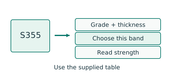
- Identify the thickness that governs this check.
- Read the matching thickness band within the correct grade.
- Use that strength consistently in the calculation.
Remember: For the supplied S355 table, thickness above 16 mm can reduce .
Source: Chapter 1 Tables 3.2/3.3 on pp.18–19; Data File p.1. For S355 in the supplied table:
| Thickness interval | () |
|---|---|
For beam bending, use the flange thickness to select as the lecture examples do. For a plate, use that plate’s thickness. For web bearing, is the web design strength. Distinguish the material design strength from the bolt shear strength , weld strength , column compressive strength , and LTB bending strength . All have stress units but answer different failure questions.
Try it yourself. Which strength applies to S355 cover plates thick and a main plate thick?
Reveal answer and reasoning
Cover: because . Main: because . Do not use one value just because both say S355.
Animation labRead a table without losing the keys
Supplement to the original lesson. Enable JavaScript to play, step through calculations and rotate 3D models. The following explanation remains readable offline.
- Name the required property: material strength, section property, buckling strength or a moment factor.
- Keep section size, steel grade, thickness band, curve and axis as separate lookup keys.
- , and require different conversion powers. Do not use adjacent columns interchangeably.
- Use bracketing rows within the same valid column. The original page remains the source of all table values.
Animation labRead a table without losing the keys
Supplement to the original lesson. Enable JavaScript to play, step through calculations and rotate 3D models. The following explanation remains readable offline.
- Name the required property: material strength, section property, buckling strength or a moment factor.
- Keep section size, steel grade, thickness band, curve and axis as separate lookup keys.
- , and require different conversion powers. Do not use adjacent columns interchangeably.
- Use bracketing rows within the same valid column. The original page remains the source of all table values.
19. Local buckling and the four classes
Simple explanation: A thin part can wrinkle first
A thin plate may wrinkle before the whole steel member reaches its intended resistance.
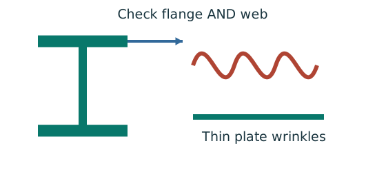
- Check flange and web slenderness using their own definitions.
- Compare each ratio with the correct class limits.
- The less favourable element determines the section class.
Remember: Bending limits and uniform-compression limits are different.
Source: Chapter 1 pp.19–22; Data File p.1. A thin plate can buckle locally before the whole member buckles sideways. Classification checks element width/depth divided by thickness. The least favourable element controls the whole cross section: Class 2 flange plus Class 3 web gives Class 3. “Lowest class” in lecture prose means worst behaviour, hence highest class number.
| Class | What can be developed? | Exam implication |
|---|---|---|
| 1: plastic | Full plastic moment and enough rotation for a plastic hinge | Plastic analysis permitted where otherwise applicable. |
| 2: compact | Full plastic moment but limited rotation | May use plastic section resistance, not assume redistribution capability. |
| 3: semi-compact | Extreme fibre can reach ; local buckling limits plastic spreading | Use elastic resistance or explicitly permitted effective properties. |
| 4: slender | Local buckling can occur before extreme fibre reaches | Effective/reduced section treatment required; gross Class 1 formulas do not apply. |
For a rolled I/H beam in major-axis bending, use Table 7.1 “outstand flange, compression due to bending, rolled section” and “web, neutral axis at mid-depth”. Flange limits are , and for Classes 1, 2 and 3. Web limits are , and . The supplied section tables already tabulate and ; do not replace clear web depth with overall depth .
For a web under combined compression and bending, use the general-web row and its parameter. The course is limited to the interval to . For positive , the Class limit is , with the table’s lower bound . For example, an initially calculated of 2.06 is limited to : . Pure-compression non-slender checks use flange and web as in the column examples; they do not prove Class rotation capacity.
A separate web slenderness check in the beam examples screens the need for shear-buckling treatment. It is not the Class 1 bending-web limit , and it does not replace concentrated-load web bearing/buckling checks.
Try it yourself. For S355 with , a rolled beam has and . Find its bending class.
Reveal answer and reasoning
and : flange is Class 2. : web is Class 1. Overall Class 2. The flange controls.
Animation labWhy thin elements buckle locally
Supplement to the original lesson. Enable JavaScript to play, step through calculations and rotate 3D models. The following explanation remains readable offline.
- The flange outstand and web have different widths, thicknesses and edge support conditions.
- A thinner plate can wrinkle locally before the complete member loses stability.
- Class 1 allows plastic rotation; Class 2 reaches plastic resistance; Class 3 reaches elastic resistance; Class 4 requires effective properties.
- Check every relevant compression element with the supplied limits and stress distribution. The deformation shown is qualitative.
Animation labWhy thin elements buckle locally
Supplement to the original lesson. Enable JavaScript to play, step through calculations and rotate 3D models. The following explanation remains readable offline.
- The flange outstand and web have different widths, thicknesses and edge support conditions.
- A thinner plate can wrinkle locally before the complete member loses stability.
- Class 1 allows plastic rotation; Class 2 reaches plastic resistance; Class 3 reaches elastic resistance; Class 4 requires effective properties.
- Check every relevant compression element with the supplied limits and stress distribution. The deformation shown is qualitative.
20. Course scope and standards: avoid mixed methods
The lecture explicitly uses the Hong Kong Code of Practice for the Structural Use of Steel 2011 for calculations (Chapter 1 p.7). The July 2026 module syllabus lists “2011 (2023 Edition)” as a reference. The supplied Data File says its tables reproduce the 2011 Code and its section properties come from an older SCI/BS 5950 design guide. Course exercises on this site follow those supplied formulas, tables and symbols. A bibliography entry does not authorise replacing their coefficients with those of another standard.
Chapter 1 pp.23–26 introduces BS 5950, GB 50017, Eurocode 3, AS 4100 and AISC, and contrasts notation. The Eurocode family is EN 1990 basis, 1991 actions, 1992 concrete, 1993 steel, 1994 composite, 1995 timber, 1996 masonry, 1997 geotechnical, 1998 earthquake and 1999 aluminium. A national implementation includes the unaltered Eurocode and can include a National Annex specifying Nationally Determined Parameters where choices are allowed.
| Meaning | Course HK notation | Eurocode notation in the lecture |
|---|---|---|
| Major cross-section axis | ||
| Minor cross-section axis | ||
| Along member | Not labelled in this course table | |
| Elastic section modulus | ||
| Plastic section modulus | ||
| Axial action | ||
| Design yield stress | ||
| Column compressive strength | ||
| LTB bending strength |
Dead load is called permanent action; imposed and wind loads are variable actions in the lecture comparison. Its Eurocode loading example uses and with combination factors. Those values are an overview topic only. Do not put them into the HK worked solutions. The p.26 label “Wrapping Index” is a source typo for warping; retain the table’s intended warping/torsion distinction when reading properties.
Animation labRead a table without losing the keys
Supplement to the original lesson. Enable JavaScript to play, step through calculations and rotate 3D models. The following explanation remains readable offline.
- Name the required property: material strength, section property, buckling strength or a moment factor.
- Keep section size, steel grade, thickness band, curve and axis as separate lookup keys.
- , and require different conversion powers. Do not use adjacent columns interchangeably.
- Use bracketing rows within the same valid column. The original page remains the source of all table values.
Unnumbered lecture arithmetic: combination coefficients
Source: Chapter 1 p.25, Table 11. This comparison explicitly assumes for wind and for imposed load. is a dimensionless accompanying-action factor, multiplied by the dimensionless action factor.
Accompanying wind coefficient
Animation labRearrange a capacity equation
Supplement to the original lesson. Enable JavaScript to play, step through calculations and rotate 3D models. The following explanation remains readable offline.
- For , P is force, p is stress and A is area. Here we want A.
- Divide both sides by the same non-zero stress p.
- The p on the right cancels, leaving .
- gives . This is required area, not a selected section or a complete design check.
Accompanying imposed coefficient
Animation labRearrange a capacity equation
Supplement to the original lesson. Enable JavaScript to play, step through calculations and rotate 3D models. The following explanation remains readable offline.
- For , P is force, p is stress and A is area. Here we want A.
- Divide both sides by the same non-zero stress p.
- The p on the right cancels, leaving .
- gives . This is required area, not a selected section or a complete design check.
Thus the two displayed illustrative combinations contain and respectively. These are not unfactored loads, not steel strengths and not alternative HK gravity coefficients. For the HK floor exercises return to .
Try it yourself. Under those illustrative assumptions only, what accompanies a wind action?
Reveal answer and reasoning
. This answer belongs to the lecture’s Eurocode comparison, not the HK worked-example loading method.
Animation labRearrange a capacity equation
Supplement to the original lesson. Enable JavaScript to play, step through calculations and rotate 3D models. The following explanation remains readable offline.
- For , P is force, p is stress and A is area. Here we want A.
- Divide both sides by the same non-zero stress p.
- The p on the right cancels, leaving .
- gives . This is required area, not a selected section or a complete design check.
Animation labRearrange a capacity equation
Supplement to the original lesson. Enable JavaScript to play, step through calculations and rotate 3D models. The following explanation remains readable offline.
- For , P is force, p is stress and A is area. Here we want A.
- Divide both sides by the same non-zero stress p.
- The p on the right cancels, leaving .
- gives . This is required area, not a selected section or a complete design check.
Practise this chapter: tutorials, assignments and past-paper answers →