Connection example 10: welded splice and a minimum-size discrepancy
Open “Animation lab” beside a teaching step for a visual explanation or a walkthrough of its original expressions. Models are illustrative; source answers remain unchanged.
← Read this lecture example beside its chapter concepts
Need a simpler picture? Open “Simple explanation” beside a difficult step. These optional notes do not replace the full solution.
Design a welded double-cover splice transferring ultimate tension between S355 main plates. Cover thickness is . Use Class 42 electrode. Explain the lecturer’s -weld solution, then reconcile it with the chapter’s minimum weld-size table.
Original source: LectureNotes/Ch 2_Connection.pdf — p. 43, p. 44. Values tagged given are in the question or diagram; lookup values come from a named table; calculated values follow from the working; assumptions are stated explicitly.
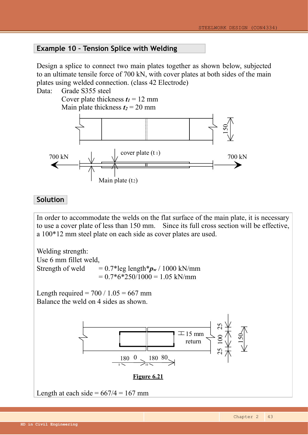
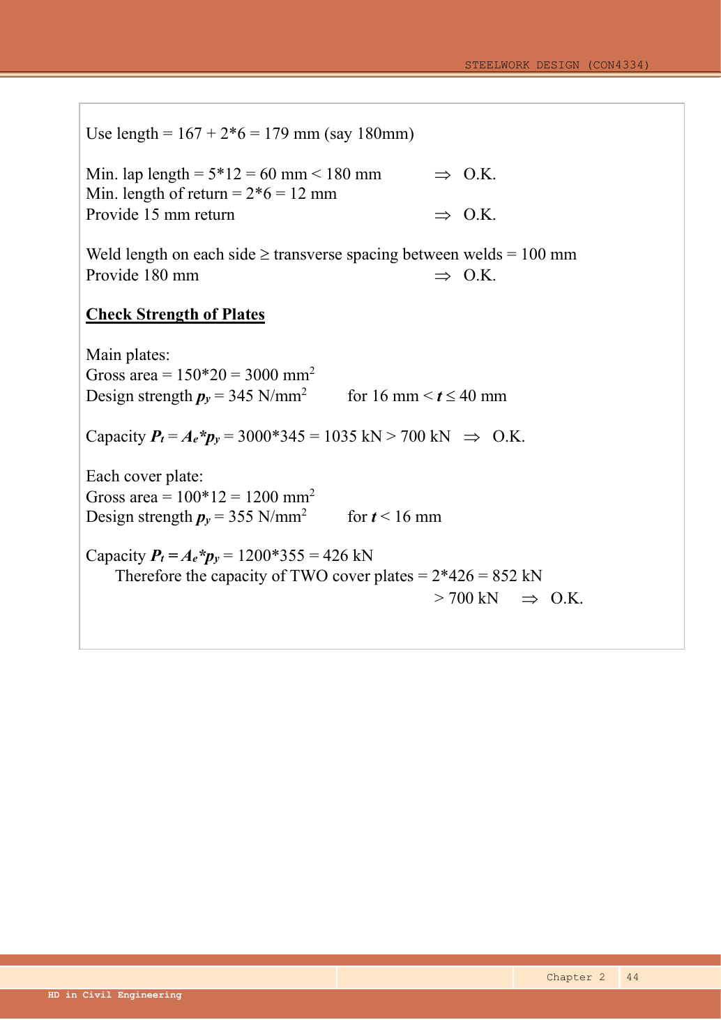
Read the diagram and collect the data
| Input | Origin |
|---|---|
| Given demand | ultimate; do not factor again. |
| Given plates | Main width and thickness ; two covers thick. |
| Selected cover width | Lecturer chooses to leave flat room for edge welds; not a given dimension. |
| Lookup | S355 for main,355 for covers. for Class 42. |
| Detailing lookup | Chapter 2 p.33 Table 9.1: thicker part over requires minimum leg . Here the thicker connected main plate is . |
Before calculating: recognition and strategy
The force enters one half-splice from the main plate and divides equally between two covers. Each cover has two longitudinal weld runs, so four runs share the on each side of the butt. Size runs using effective length, check laps/returns and check unperforated plate tension. The lecturer’s strength arithmetic is reproducible, but a final choice must also satisfy the supplied minimum-size rule.
1. Select and interpret the covers
This is an explicit design choice providing space to place the weld on the main plate. Two covers have combined thickness but are checked individually at half force . The source uses the full welded plate area: no bolt-hole deductions.
Animation labTension through an unperforated plate
Supplement to the original lesson. Enable JavaScript to play, step through calculations and rotate 3D models. The following explanation remains readable offline.
- For this concentric, unperforated plate, the full width and thickness form the resisting section. There are no bolt holes to deduct.
- The illustrative width is 100 mm. Adjust thickness t: , in .
- Using illustrative , in kN. Use the actual material and thickness band for the original question.
- The covers are moved apart for visibility. A symmetric pair each carries half the force. Check the main plate, each cover and the welds separately.
2. Reproduce the lecturer’s strength calculation
Simple explanation: Drawn length and useful length differ
The start and end of a weld are not credited as fully effective in this course model.
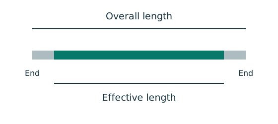
- Find the effective length required by strength.
- Add the specified end allowance to each separate run.
- Round up, then check minimum size, spacing and returns.
Remember: Strength alone does not prove a weld detail is acceptable.
The four runs on the other side of the butt transfer the same in series. Do not add both halves to claim splice resistance.
Animation labFrom fillet leg to effective throat
Supplement to the original lesson. Enable JavaScript to play, step through calculations and rotate 3D models. The following explanation remains readable offline.
- An equal-leg fillet between perpendicular plates has an approximately right-triangular section.
- For this geometry, throat . It is shorter than the leg.
- Effective resisting area = . With here, capacity per length is .
- Use the course end allowances, minimum size and length rules; increasing the geometric length alone does not resolve every detailing check.
3. Reconcile the minimum-size table and give a corrected detail
The lecturer checks lap, physical run transverse spacing, and returns . However the main plate triggers the minimum in Table 9.1 on p.33; the selection is inconsistent with that supplied table.
The corrected detail uses fillets, physical longitudinal runs on each half of each cover edge, and returns. This is an authored correction, clearly distinguished from the lecturer’s dimensions.
Animation labFrom fillet leg to effective throat
Supplement to the original lesson. Enable JavaScript to play, step through calculations and rotate 3D models. The following explanation remains readable offline.
- An equal-leg fillet between perpendicular plates has an approximately right-triangular section.
- For this geometry, throat . It is shorter than the leg.
- Effective resisting area = . With here, capacity per length is .
- Use the course end allowances, minimum size and length rules; increasing the geometric length alone does not resolve every detailing check.
4. Verify main and cover plate tension
Simple explanation: Why holes reduce tension resistance
The pull must squeeze through the steel left beside the holes.
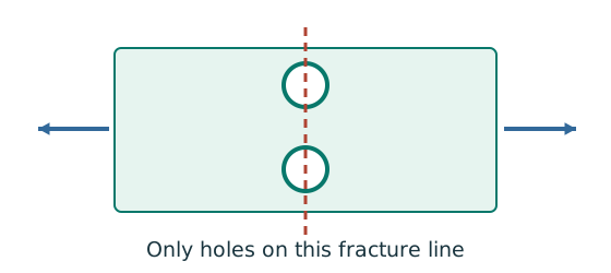
- Choose a possible fracture line across the member.
- Subtract the holes crossed by that line using hole diameter.
- Apply the course effective-area rule and its gross-area limit.
Remember: Do not subtract every hole anywhere in the connection.
The corrected welded load path is governed by weld resistance, above . Main and cover tension pass. Every area is unperforated, so it equals the effective area for this concentric plate connection.
Animation labTension through an unperforated plate
Supplement to the original lesson. Enable JavaScript to play, step through calculations and rotate 3D models. The following explanation remains readable offline.
- For this concentric, unperforated plate, the full width and thickness form the resisting section. There are no bolt holes to deduct.
- The illustrative width is 100 mm. Adjust thickness t: , in .
- Using illustrative , in kN. Use the actual material and thickness band for the original question.
- The covers are moved apart for visibility. A symmetric pair each carries half the force. Check the main plate, each cover and the welds separately.
Compact exam answer
Source arithmetic: fillets, physical runs give per half; plates give main and cover pair. But Table 9.1 requires for the thicker part. Corrected detail: fillets, physical runs on each of four runs per half, returns. Effective length /run gives ; lap, length and edge-leg limits pass.
Mistakes to avoid
- Four parallel runs occur on each half-splice; opposite halves are in series.
- The cover width is selected, not the main width.
- Strength adequacy does not override the supplied minimum weld-size table.
- Increasing leg size changes the length deduction.
Procedure for an unfamiliar variant
- Select cover width with room for welds and check plate strength.
- Count parallel weld runs on one transfer side only.
- Find required effective length, add and round up.
- Check minimum/maximum leg, lap, returns and transverse-spacing rules.
- Resolve source discrepancies explicitly and verify the corrected detail.
Independent self-check
Try it yourself. For the corrected welds, would physical longitudinal runs be sufficient?
Hint
Recompute effective length after selecting the physical length.
Reveal answer and reasoning
Effective length . Resistance, so no. Rounding the minimum down to loses required capacity.
Animation labFrom fillet leg to effective throat
Supplement to the original lesson. Enable JavaScript to play, step through calculations and rotate 3D models. The following explanation remains readable offline.
- An equal-leg fillet between perpendicular plates has an approximately right-triangular section.
- For this geometry, throat . It is shorter than the leg.
- Effective resisting area = . With here, capacity per length is .
- Use the course end allowances, minimum size and length rules; increasing the geometric length alone does not resolve every detailing check.