Steelwork · Exam learning

2022–2024 · Exam-focused route

2023 FT/PTD BQ4 — overhang and LTB Section B · choose 2 of 3

This is the main recent-paper variant to practise after a simply supported beam: support identification changes the entire analysis.

Original source: 22ENGTY006.pdf · physical page 6

Note: marks are as printed in the paper; the working is a teaching guide, not an official marking scheme.

An overhang, not a support at A

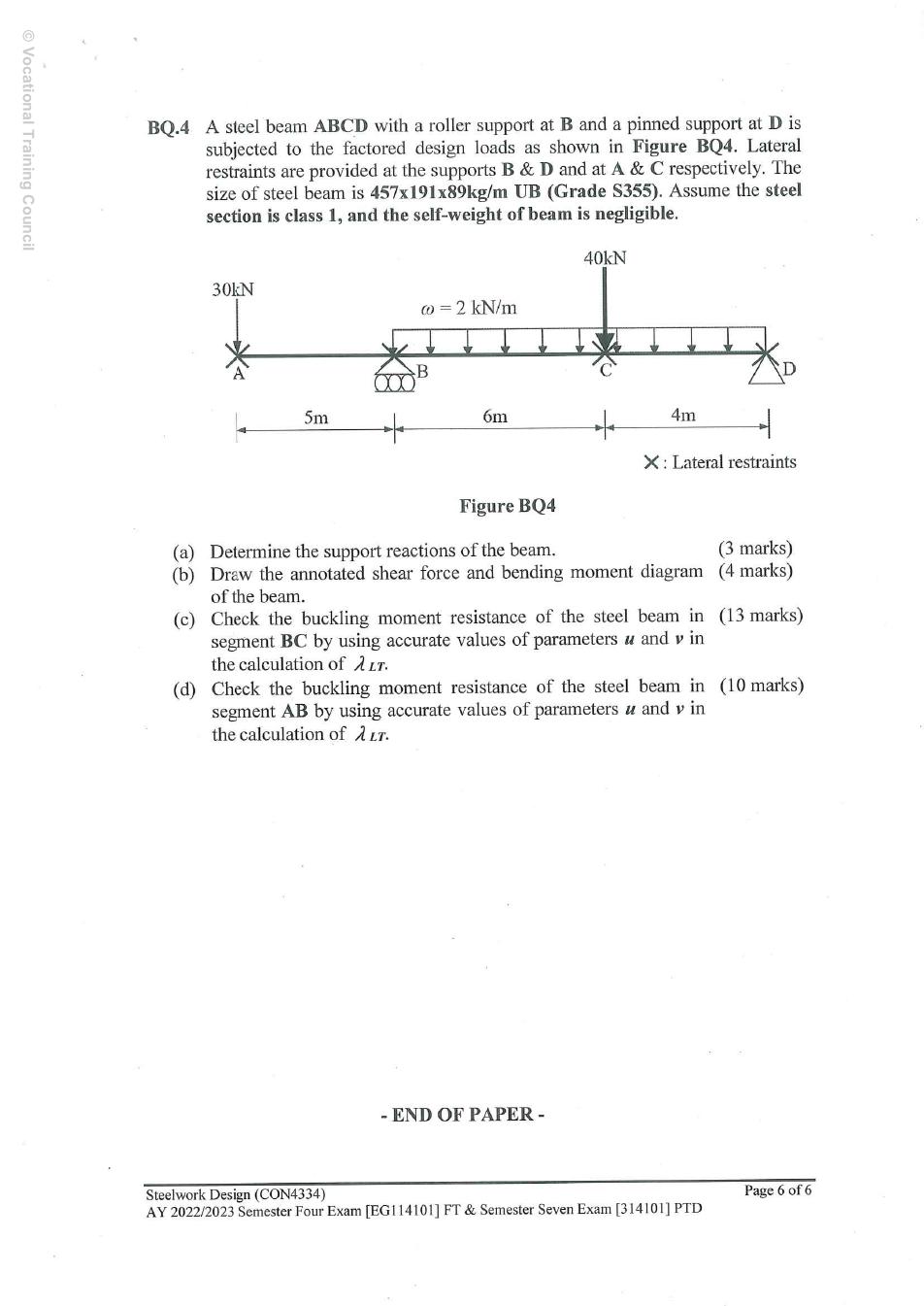
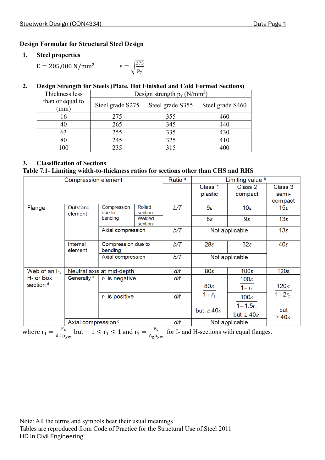
The roller is at B and the pin at D. A is a free vertical tip with a lateral-restraint cross; C is another lateral restraint. Coordinates from A are 0, 5, 11 and 15 m. Factored downward loads: 30 kN at A, 40 kN at C, and 2 kN/m only from B to D. Self-weight is negligible. The S355 457 × 191 × 89 UB is given as Class 1.

Simple explanation — open only if needed

The left overhang behaves like a diving board sticking beyond its support. A downward force at its free tip creates hogging at B. The cross at A stops sideways movement; it does not lift the beam up, so there is no vertical reaction at A.

BQ4(a) — support reactions [3 marks]

Take counter-clockwise moments as positive about B. The left-tip force rotates in the opposite sense to loads on the right. The 20 kN UDL resultant is at the midpoint of BD, 5 m to the right of B.

W=2(6+4)=20 kNW=2(6+4)=20\,\mathrm{kN}
∑MB=0:10RD+30(5)−40(6)−20(5)=0\sum M_B=0:\quad10R_D+30(5)-40(6)-20(5)=0
RD=240+100−15010=19 kN,RB=30+40+20−19=71 kNR_D=\frac{240+100-150}{10}=19\,\mathrm{kN},\quad R_B=30+40+20-19=71\,\mathrm{kN}

Check total upward reaction 90 kN against the total downward load 90 kN.

BQ4(b) — annotated SFD and BMD [4 marks]

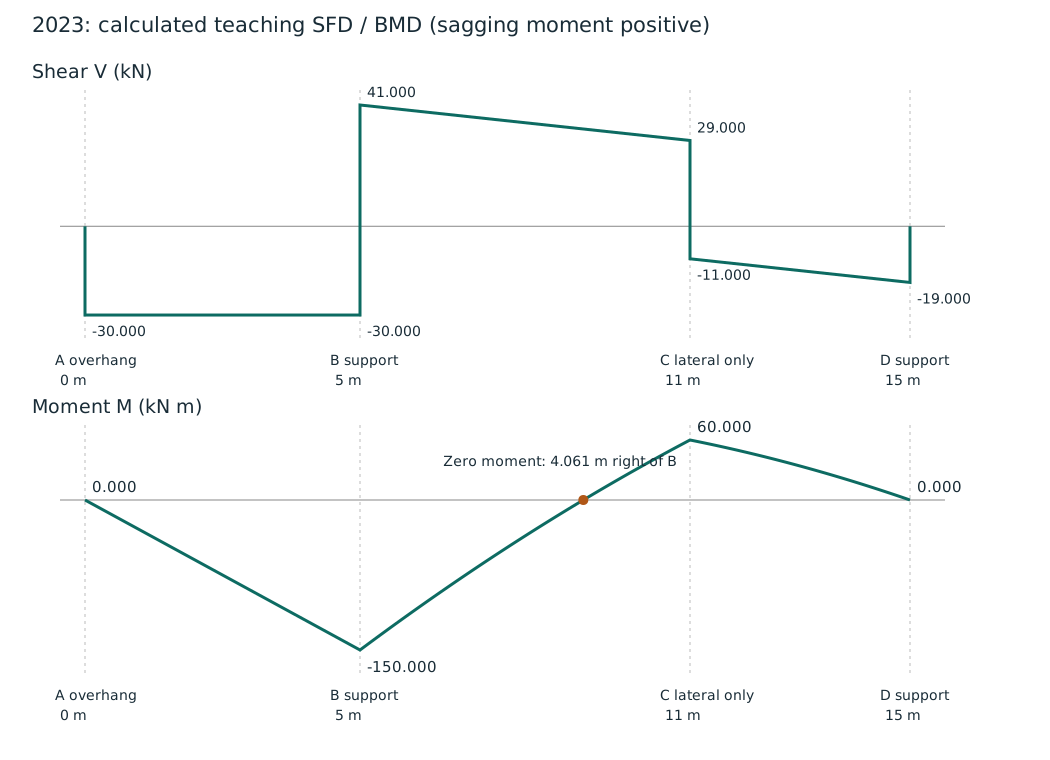
Choose positive sagging moment. On AB, x is measured from A; on BC, s is measured from B; on CD, t is measured from C. Keep these origins explicit. At B and C the bending moment is continuous, even though shear jumps.

AB:V=−30 kN,M=−30x kN m(0≤x≤5)AB:\quad V=-30\,\mathrm{kN},\quad M=-30x\,\mathrm{kN\,m}\quad(0\le x\le5)
MB=−30(5)=−150 kN m,VB+=−30+71=41 kNM_B=-30(5)=-150\,\mathrm{kN\,m},\quad V_{B+}=-30+71=41\,\mathrm{kN}
BC:V=41−2s,M=−150+41s−s2(0≤s≤6)BC:\quad V=41-2s,\quad M=-150+41s-s^2\quad(0\le s\le6)
VC−=41−2(6)=29 kN,MC=−150+41(6)−62=60 kN mV_{C-}=41-2(6)=29\,\mathrm{kN},\quad M_C=-150+41(6)-6^2=60\,\mathrm{kN\,m}
VC+=29−40=−11 kNV_{C+}=29-40=-11\,\mathrm{kN}
CD:V=−11−2t,M=60−11t−t2(0≤t≤4)CD:\quad V=-11-2t,\quad M=60-11t-t^2\quad(0\le t\le4)
VD−=−11−2(4)=−19 kN,MD=60−11(4)−42=0V_{D-}=-11-2(4)=-19\,\mathrm{kN},\quad M_D=60-11(4)-4^2=0

The BD moment diagram changes sign within BC. Solve the quadratic and choose the root that lies inside the 6 m segment; the other root is outside and has no physical relevance here.

−150+41s−s2=0⇒s=41±412−4(150)2-150+41s-s^2=0\Rightarrow s=\frac{41\pm\sqrt{41^2-4(150)}}2
s=41−10812=4.060718 mfrom Bs=\frac{41-\sqrt{1081}}2=4.060718\,\mathrm{m}\quad\text{from B}

Shear is positive throughout BC, so moment increases from −150 to +60; the largest absolute moment is 150 kN·m at B. CD decreases from +60 to zero. AB is a straight negative triangle because it has no UDL.

Calculated SFD/BMD: B is the vertical support at 5 m, the zero-moment point is 4.060718 m right of B.
Calculated SFD/BMD: B is the vertical support at 5 m, the zero-moment point is 4.060718 m right of B. Full-size image

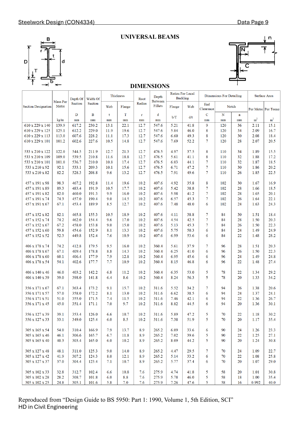
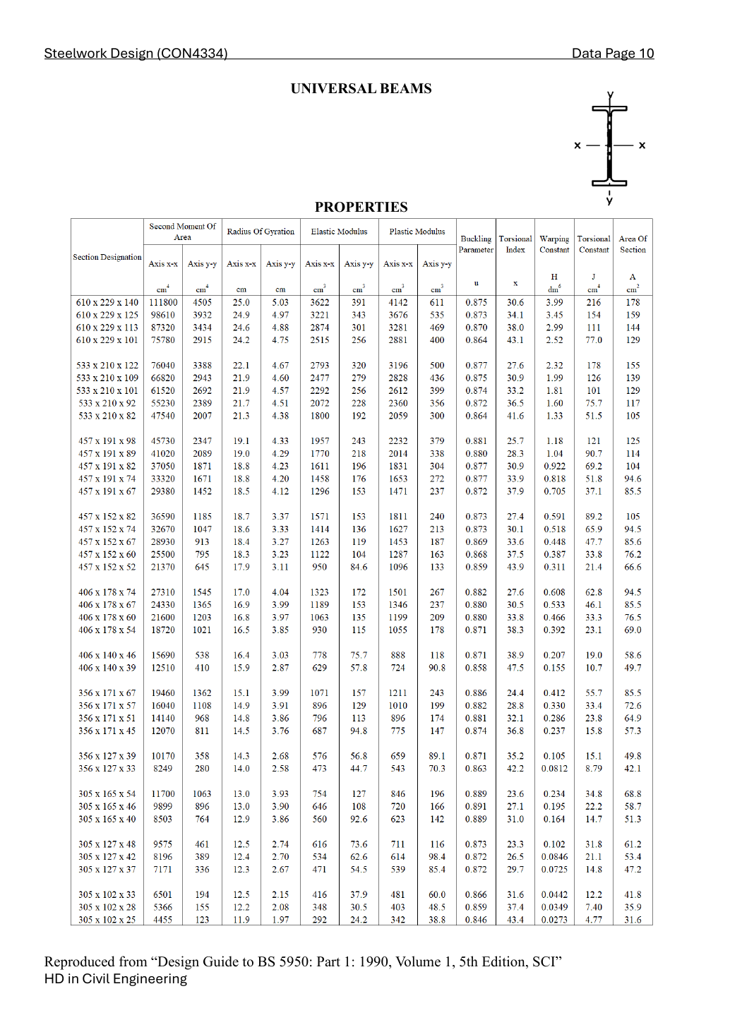
Look up the exact UB row

Source: LectureNotes/CON4334-Data File-20260730.pdf · p.1, p.9, p.10
T=17.7 mm⇒py=345 N/mm2,ry=4.29 cm=42.9 mmT=17.7\,\mathrm{mm}\Rightarrow p_y=345\,\mathrm{N/mm^2},\quad r_y=4.29\,\mathrm{cm}=42.9\,\mathrm{mm}
u=0.880,x=28.3,Sx=2014 cm3,βW=1u=0.880,\quad x=28.3,\quad S_x=2014\,\mathrm{cm^3},\quad\beta_W=1

BQ4(c) — segment BC [13 marks]

Evaluate the BC formula at s = 1.5, 3 and 4.5 m from B. These correspond to global x = 6.5, 8 and 9.5 m from A.

M(s=1.5)=−150+41(1.5)−1.52=−90.75 kN mM(s=1.5)=-150+41(1.5)-1.5^2=-90.75\,\mathrm{kN\,m}
M(s=3)=−150+41(3)−32=−36 kN mM(s=3)=-150+41(3)-3^2=-36\,\mathrm{kN\,m}
M(s=4.5)=−150+41(4.5)−4.52=14.25 kN mM(s=4.5)=-150+41(4.5)-4.5^2=14.25\,\mathrm{kN\,m}
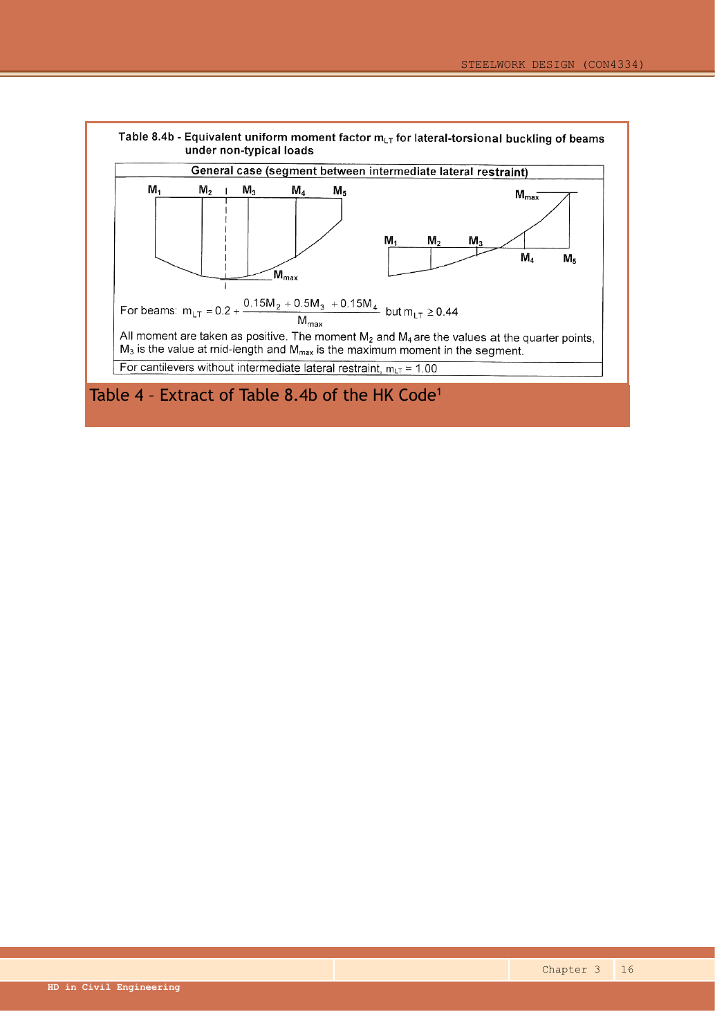
Source: LectureNotes/Ch3_Beam.pdf · p.16

Use the moments at one-quarter, one-half and three-quarters of THIS restrained segment. They are not necessarily at load points. Evaluate the actual quadratic bending diagram including the UDL; use absolute magnitudes in the quarter-point expression and compare with the maximum absolute moment in the segment.

Quarter point coordinateMoment (kN·m)
x=6.5 mx=6.5\,\mathrm{m}M=−90.75 kN mM=-90.75\,\mathrm{kN\,m}
x=8 mx=8\,\mathrm{m}M=−36 kN mM=-36\,\mathrm{kN\,m}
x=9.5 mx=9.5\,\mathrm{m}M=14.25 kN mM=14.25\,\mathrm{kN\,m}
mLT=max⁡(0.44, 0.2+0.15∣M2∣+0.5∣M3∣+0.15∣M4∣∣Mmax∣)m_{LT}=\max\left(0.44,\ 0.2+\frac{0.15|M_2|+0.5|M_3|+0.15|M_4|}{|M_{max}|}\right)
mLT=max⁡(0.44, 0.2+0.15∣−90.75∣+0.5∣−36∣+0.15∣14.25∣150)m_{LT}=\max\left(0.44,\ 0.2+\frac{0.15|-90.75|+0.5|-36|+0.15|14.25|}{150}\right)
mLT=max⁡(0.44,0.425)=0.44m_{LT}=\max(0.44,0.425)=0.44

Use millimetres in slenderness. The section table supplies the minor-axis radius of gyration, buckling parameter and torsional index; the given Class 1 section has a plastic-section factor of one. These quantities change when the section changes.

LE=6000  mm,ry=42.9  mm,u=0.88,x=28.3,βW=1L_E=6000\;\mathrm{mm},\quad r_y=42.9\;\mathrm{mm},\quad u=0.88,\quad x=28.3,\quad\beta_W=1
λ=LEry=600042.9=139.86014\lambda=\frac{L_E}{r_y}=\frac{6000}{42.9}=139.86014
v=[1+0.05(λx)2]−1/4=[1+0.05(139.8601428.3)2]−1/4=0.819131v=\left[1+0.05\left(\frac{\lambda}{x}\right)^2\right]^{-1/4}=\left[1+0.05\left(\frac{139.86014}{28.3}\right)^2\right]^{-1/4}=0.819131
λLT=uvλβW=0.88×0.819131×139.86014=100.816114\lambda_{LT}=uv\lambda\sqrt{\beta_W}=0.88\times0.819131\times139.86014=100.816114
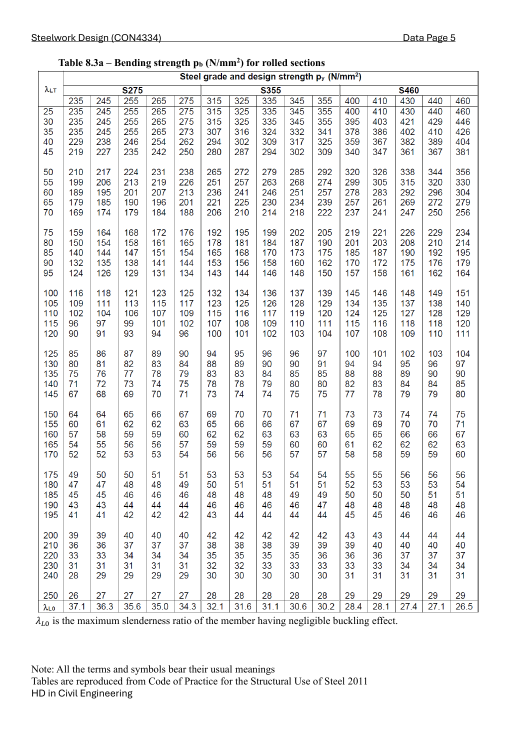
Source: LectureNotes/CON4334-Data File-20260730.pdf · p.5

Choose Data File p.5, Table 8.3, 345 N/mm² column. Interpolate between the two surrounding slenderness rows in the same design-strength column; do not mix columns.

pb=137+100.816114−100105−100(128−137)=135.530994  N/mm2p_b=137+\frac{100.816114-100}{105-100}(128-137)=135.530994\;\mathrm{N/mm^2}

Buckling strength times plastic modulus gives moment resistance. Convert the tabulated cubic centimetres to cubic millimetres, then newton-millimetres to kilonewton-metres.

Mb=pbSx×103106=135.530994×20141000=272.959423  kN mM_b=\frac{p_b S_x\times10^3}{10^6}=\frac{135.530994\times2014}{1000}=272.959423\;\mathrm{kN\,m}
mLTMmax=0.44×150=66  kN mm_{LT}M_{max}=0.44\times150=66\;\mathrm{kN\,m}
mLTMmaxMb=66272.959423=0.241794≤1\frac{m_{LT}M_{max}}{M_b}=\frac{66}{272.959423}=0.241794\le1

The stated effective-length model passes this LTB check.

BQ4(d) — cantilever AB, conditional branches [10 marks]

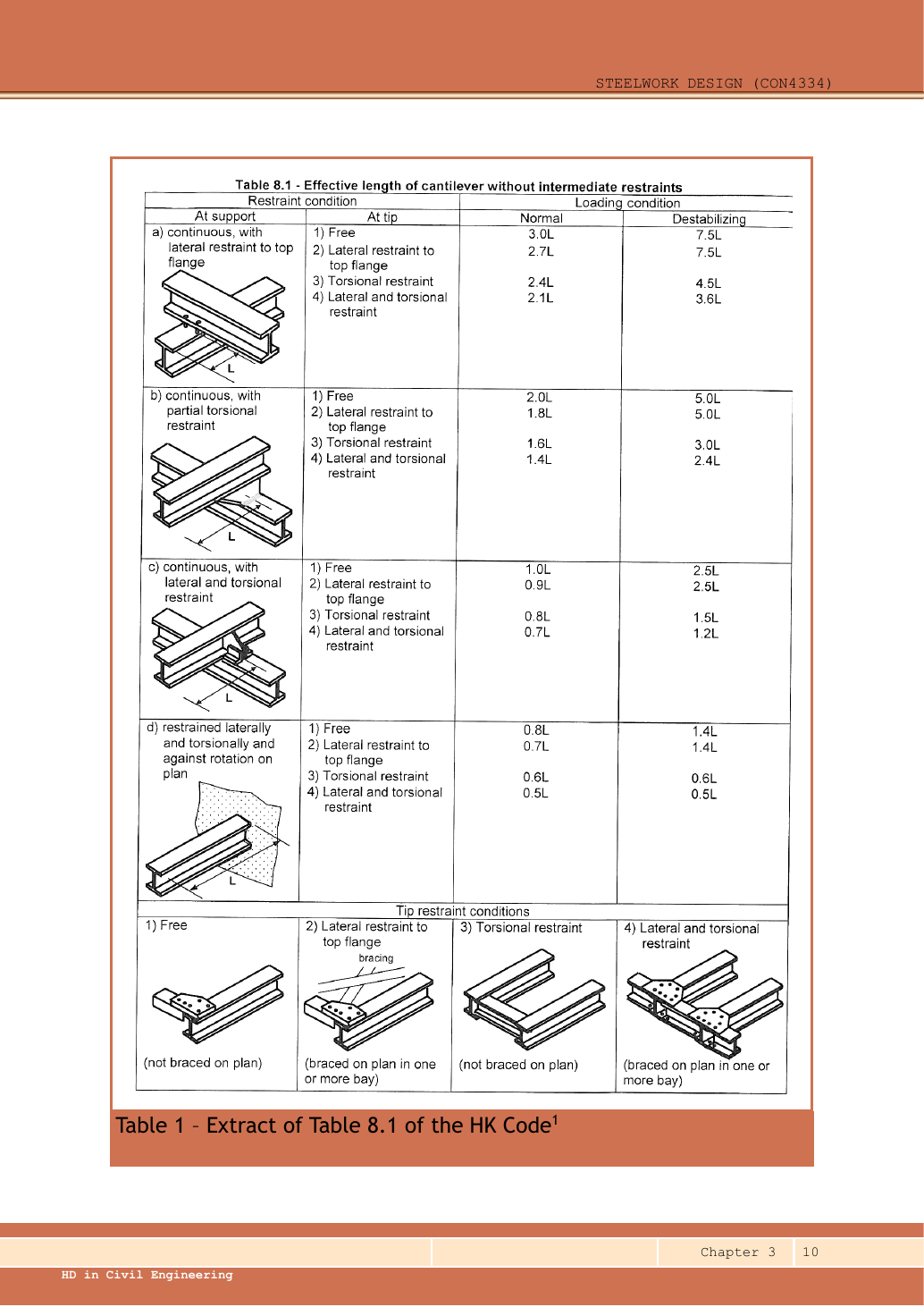
Source: LectureNotes/Ch3_Beam.pdf · p.10, p.16

AB is a cantilever segment without an intermediate lateral restraint. The course cantilever moment-factor rule is mLT = 1, even though its bending diagram is triangular. The simply supported end-moment factor is not applicable.

mLT=1,∣Mmax∣=150 kN m,mLT∣Mmax∣=150 kN mm_{LT}=1,\quad |M_{max}|=150\,\mathrm{kN\,m},\quad m_{LT}|M_{max}|=150\,\mathrm{kN\,m}
Course Table 8.1: cantilever effective length. Read support row, tip condition and loading column together.
Course Table 8.1: cantilever effective length. Read support row, tip condition and loading column together. Full-size image

Branch 1: continuous support with lateral AND torsional restraint (row c), tip lateral restraint to top flange (tip 2), NORMAL loading. Table value 0.9L gives 4,500 mm.

LE=0.9(5000)=4500 mmL_E=0.9(5000)=4500\,\mathrm{mm}

Use millimetres in slenderness. The section table supplies the minor-axis radius of gyration, buckling parameter and torsional index; the given Class 1 section has a plastic-section factor of one. These quantities change when the section changes.

LE=4500  mm,ry=42.9  mm,u=0.88,x=28.3,βW=1L_E=4500\;\mathrm{mm},\quad r_y=42.9\;\mathrm{mm},\quad u=0.88,\quad x=28.3,\quad\beta_W=1
λ=LEry=450042.9=104.895105\lambda=\frac{L_E}{r_y}=\frac{4500}{42.9}=104.895105
v=[1+0.05(λx)2]−1/4=[1+0.05(104.89510528.3)2]−1/4=0.877458v=\left[1+0.05\left(\frac{\lambda}{x}\right)^2\right]^{-1/4}=\left[1+0.05\left(\frac{104.895105}{28.3}\right)^2\right]^{-1/4}=0.877458
λLT=uvλβW=0.88×0.877458×104.895105=80.996104\lambda_{LT}=uv\lambda\sqrt{\beta_W}=0.88\times0.877458\times104.895105=80.996104
Source: LectureNotes/CON4334-Data File-20260730.pdf · p.5

Choose Data File p.5, Table 8.3, 345 N/mm² column. Interpolate between the two surrounding slenderness rows in the same design-strength column; do not mix columns.

pb=187+80.996104−8085−80(173−187)=184.21091  N/mm2p_b=187+\frac{80.996104-80}{85-80}(173-187)=184.21091\;\mathrm{N/mm^2}

Buckling strength times plastic modulus gives moment resistance. Convert the tabulated cubic centimetres to cubic millimetres, then newton-millimetres to kilonewton-metres.

Mb=pbSx×103106=184.21091×20141000=371.000772  kN mM_b=\frac{p_b S_x\times10^3}{10^6}=\frac{184.21091\times2014}{1000}=371.000772\;\mathrm{kN\,m}
mLTMmax=1×150=150  kN mm_{LT}M_{max}=1\times150=150\;\mathrm{kN\,m}
mLTMmaxMb=150371.000772=0.404312≤1\frac{m_{LT}M_{max}}{M_b}=\frac{150}{371.000772}=0.404312\le1

The stated effective-length model passes this LTB check.

Branch 2: continuous support with lateral restraint to top flange only (row a), the same tip condition 2 and NORMAL loading. Table value 2.7L gives 13,500 mm.

LE=2.7(5000)=13500 mmL_E=2.7(5000)=13500\,\mathrm{mm}

Use millimetres in slenderness. The section table supplies the minor-axis radius of gyration, buckling parameter and torsional index; the given Class 1 section has a plastic-section factor of one. These quantities change when the section changes.

LE=13500  mm,ry=42.9  mm,u=0.88,x=28.3,βW=1L_E=13500\;\mathrm{mm},\quad r_y=42.9\;\mathrm{mm},\quad u=0.88,\quad x=28.3,\quad\beta_W=1
λ=LEry=1350042.9=314.685315\lambda=\frac{L_E}{r_y}=\frac{13500}{42.9}=314.685315
v=[1+0.05(λx)2]−1/4=[1+0.05(314.68531528.3)2]−1/4=0.610849v=\left[1+0.05\left(\frac{\lambda}{x}\right)^2\right]^{-1/4}=\left[1+0.05\left(\frac{314.685315}{28.3}\right)^2\right]^{-1/4}=0.610849
λLT=uvλβW=0.88×0.610849×314.685315=169.15828\lambda_{LT}=uv\lambda\sqrt{\beta_W}=0.88\times0.610849\times314.685315=169.15828
Source: LectureNotes/CON4334-Data File-20260730.pdf · p.5

Choose Data File p.5, Table 8.3, 345 N/mm² column. Interpolate between the two surrounding slenderness rows in the same design-strength column; do not mix columns.

pb=60+169.15828−165170−165(57−60)=57.505032  N/mm2p_b=60+\frac{169.15828-165}{170-165}(57-60)=57.505032\;\mathrm{N/mm^2}

Buckling strength times plastic modulus gives moment resistance. Convert the tabulated cubic centimetres to cubic millimetres, then newton-millimetres to kilonewton-metres.

Mb=pbSx×103106=57.505032×20141000=115.815134  kN mM_b=\frac{p_b S_x\times10^3}{10^6}=\frac{57.505032\times2014}{1000}=115.815134\;\mathrm{kN\,m}
mLTMmax=1×150=150  kN mm_{LT}M_{max}=1\times150=150\;\mathrm{kN\,m}
mLTMmaxMb=150115.815134=1.295168>1\frac{m_{LT}M_{max}}{M_b}=\frac{150}{115.815134}=1.295168>1

The stated effective-length model fails this LTB check.

One case passes and the other fails. So in the exam, write which row and column of Table 8.1 you chose and why — do not just write “passes”. If the load is destabilizing, use that column of the table and recalculate.

Compact exam script

Reveal the exam script
RB=71, RD=19[kN];MB=−150, MC=60[kN m]R_B=71,\ R_D=19\quad[\mathrm{kN}];\quad M_B=-150,\ M_C=60\quad[\mathrm{kN\,m}]
BC: mLT=0.44,66<272.959423[kN m]BC:\ m_{LT}=0.44,\quad66<272.959423\quad[\mathrm{kN\,m}]
AB: mLT=1;LE=4500⇒Mb=371.000772;LE=13500⇒Mb=115.815134[kN m]AB:\ m_{LT}=1;\quad L_E=4500\Rightarrow M_b=371.000772;\quad L_E=13500\Rightarrow M_b=115.815134\quad[\mathrm{kN\,m}]

BC passes its stated branch. AB needs the cantilever restraint/loading conditions before a unique pass/fail decision; show the chosen conditional branch.

Common mistakes

  • Do not put a vertical reaction at A.
  • Do not extend the UDL onto AB.
  • A triangular cantilever diagram does not justify the simple-span mLT formula.

Procedure for a new variant

  1. Mark actual vertical supports and the loaded length.
  2. Solve reactions, signed diagrams and any contraflexure point.
  3. For each segment choose the correct beam/cantilever model and restraints.
  4. Calculate table-based LTB and state unresolved conditions.

Independent self-check — invented variant

Invented variant: the 30 kN load at A is removed. Find the new reactions and moment at B.

Hint

Repeat moment equilibrium about B.

Answer and reasoning
RD=[40(6)+20(5)]/10=34 kN,RB=60−34=26 kN,MB=0R_D=[40(6)+20(5)]/10=34\,\mathrm{kN},\quad R_B=60-34=26\,\mathrm{kN},\quad M_B=0

An unloaded free overhang carries no bending moment in this idealized model. The reactions change even though the support locations do not.