Note: marks are as printed in the paper; the working is a teaching guide, not an official marking scheme.
Read the splice and choose one complete load path
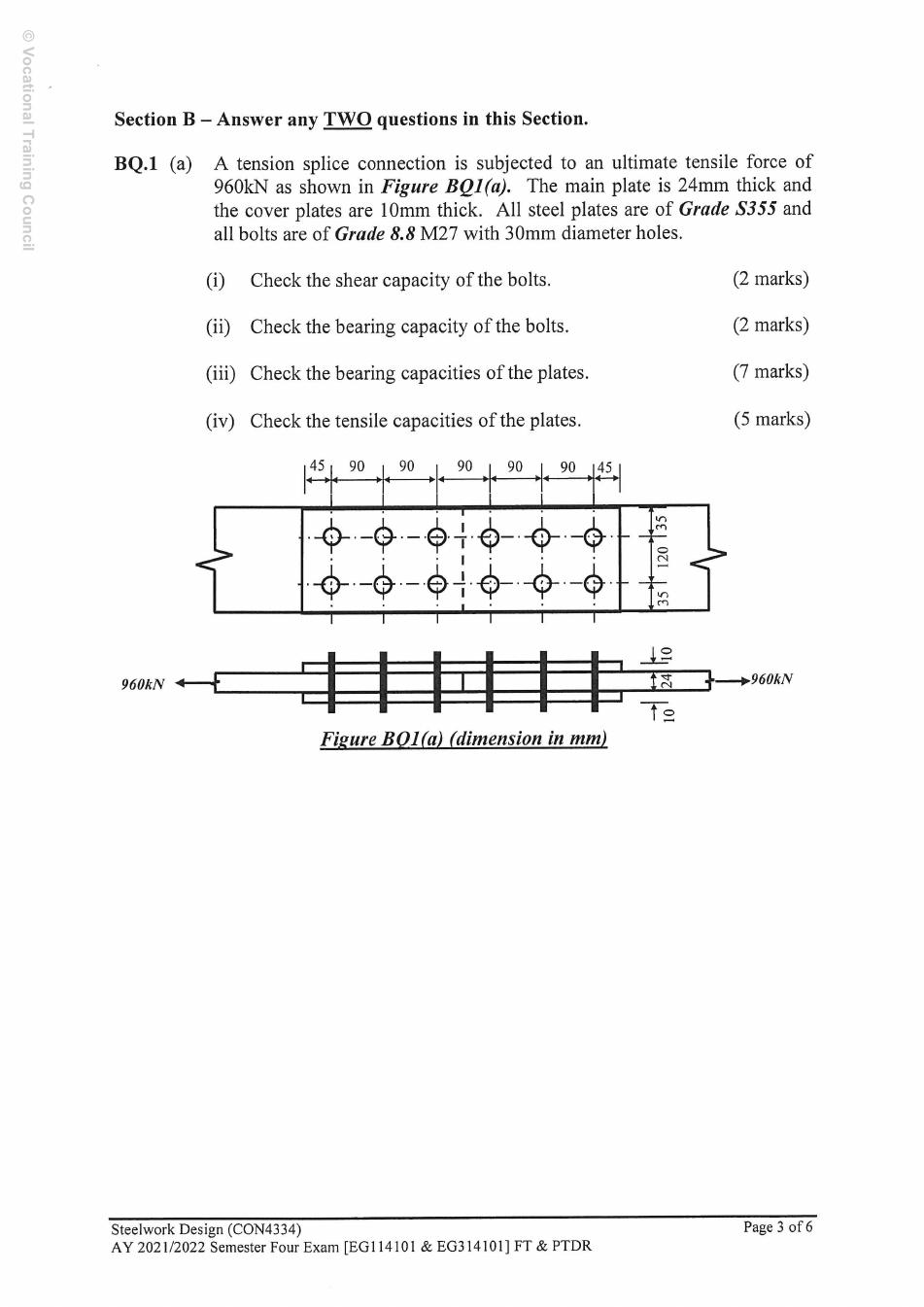
Given ultimate tension 960 kN: do not factor it again. The side elevation shows a 24 mm main plate between two 10 mm covers. The plan has two bolt rows, gauge 120 mm and side edges 35 mm each, so the width is 190 mm. Three bolt columns lie on each side of the butt joint: six bolts per half, twelve physically. Each half transfers the full force; each cover carries 480 kN.
Simple explanation — open only if needed
Two groups in series act like two links in a chain: the same force passes through each. The two identical covers act in parallel and share the force. These are different reasons for a factor of two.
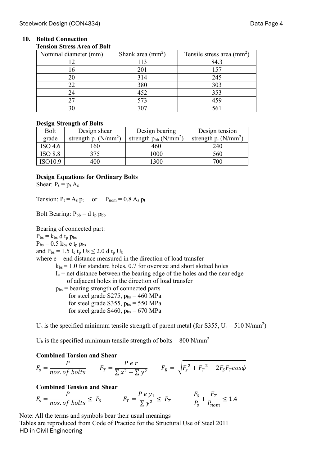
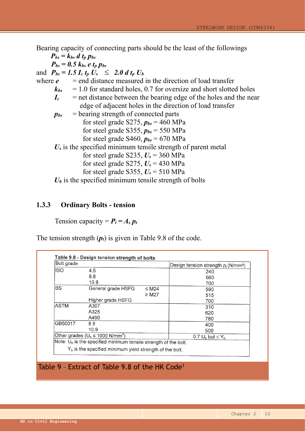
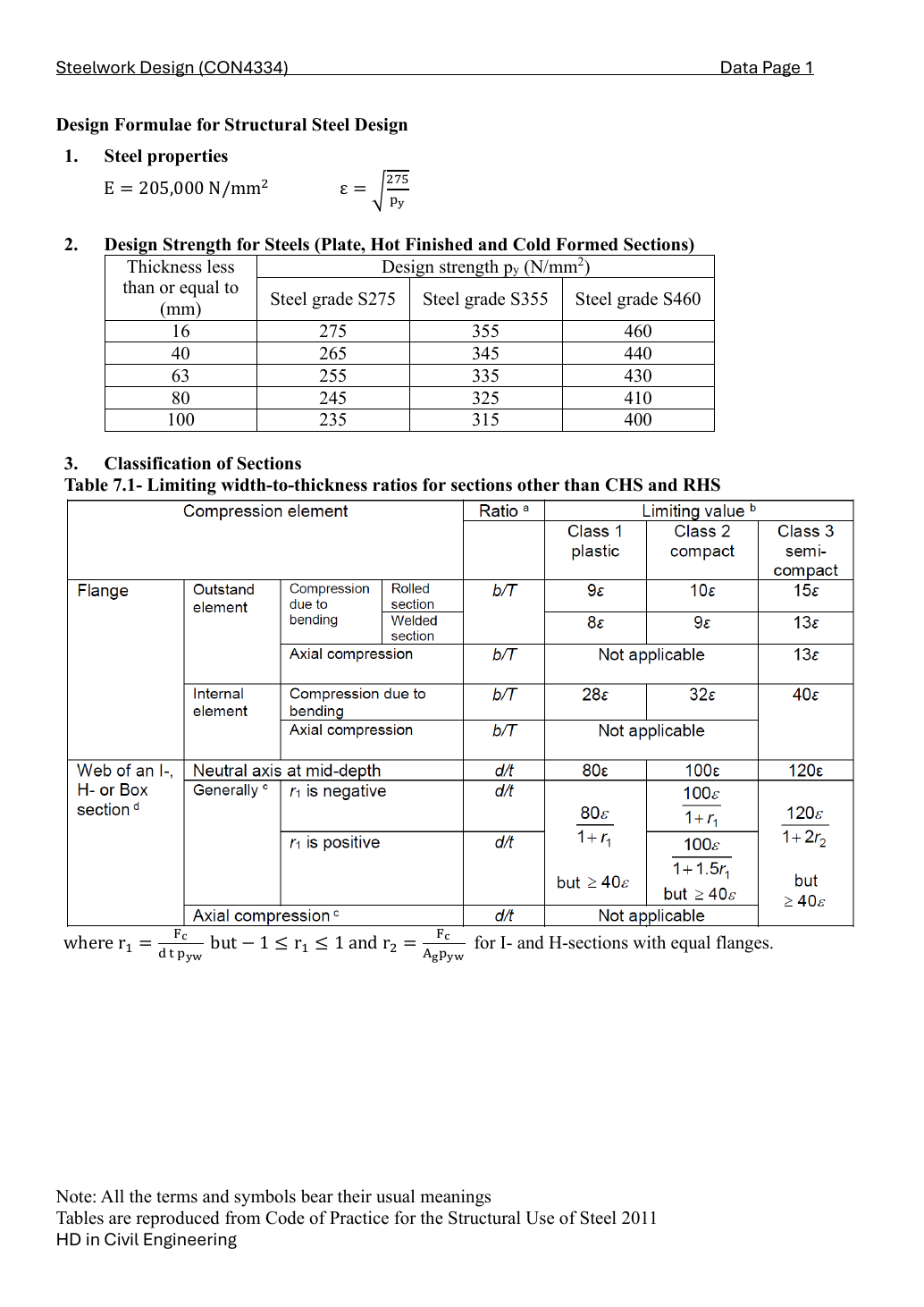
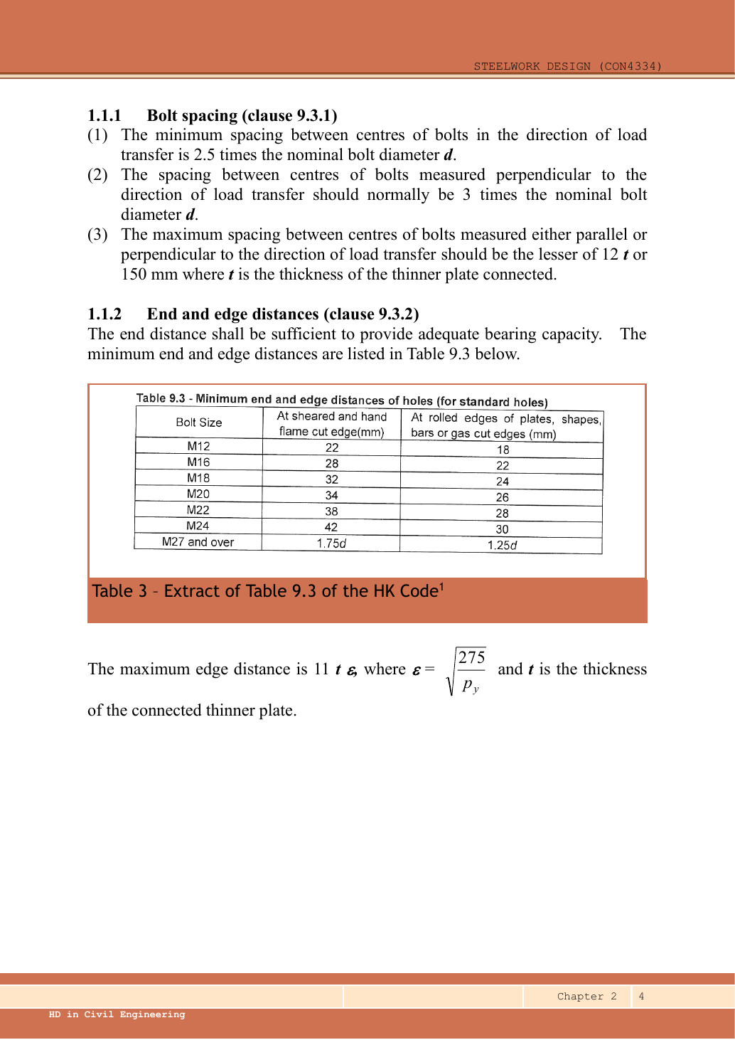
Lookups: Data File p.4, M27 tensile-stress-area row and ISO 8.8 strength row. Use thread area conservatively because a thread-free shear plane is not specified. For S355 plate bearing use 550 N/mm² and ultimate parent-metal strength 510 N/mm²; bolt ultimate strength is 800 N/mm². Ordinary 30 mm holes for M27 give the standard-hole factor one.
d=27mm,d0=30mm,As=459mm2,kbs=1,Ke=1.1
ps=375,pbb=1000,pbs=550,Us=510,Ub=800[N/mm2]
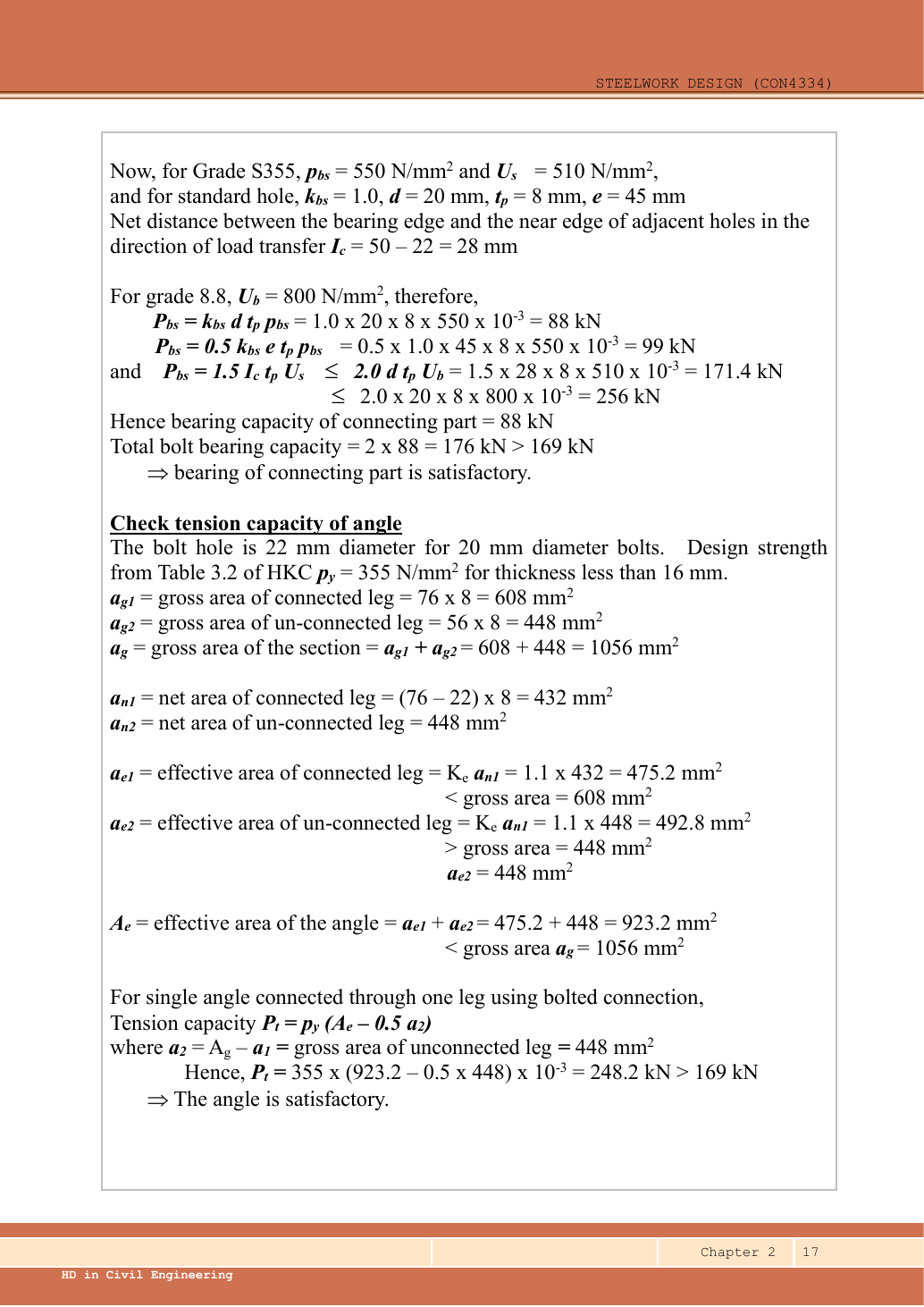
Symbols: d is bolt diameter; d₀ hole diameter; Aₛ bolt stress area; pₛ shear strength; pbb bolt bearing strength; pbs connected-part bearing strength; Ke net-area coefficient. Subtract d₀ from metal width, but use d in bearing resistance. Stress × mm² gives N; divide by 1,000 for kN.
BQ1(a)(i) — bolt shear [2 marks]
The main-to-cover interfaces create two shear planes per bolt. Count six bolts on one half-splice.
Ps,one=2Asps/1000=2(459)(375)/1000=344.25kN
Ps,half=6(344.25)=2065.5kN>960kN
BQ1(a)(ii) — bolt bearing [2 marks]
Compare the middle-ply bearing thickness with the sum of the two symmetric outer plies. This is not an extra shear-plane multiplier.
The drawing gives a pitch of 90 mm and a cover-plate end distance of 45 mm. The joint between the two main plates is drawn between the middle bolt columns, but its exact position is not dimensioned. We assume the joint is centred, so the main-plate end distance is also 45 mm on each side — say so in your answer. Then check the 24 mm main plate and each 10 mm cover separately.
The end distance is measured parallel to the force, from the free end to the nearest bolt centre. The clear inter-hole ligament is pitch minus one hole diameter. Use the smallest applicable bound; using the end-bolt bound for every bolt is conservative for the interior bolts.
If you do not assume a centred joint, keep the shorter main-plate end distance e as an unknown. Each bolt must carry 160 kN and every other limit is above that, so the condition below gives the smallest e that works for strength.
Pbs,one=min(356.4,6.6e,1101.6,1036.8)kN,e[mm]
6.6e≥960/6=160⟹e≥24.242424mm
The end distance is measured parallel to the force, from the free end to the nearest bolt centre. The clear inter-hole ligament is pitch minus one hole diameter. Use the smallest applicable bound; using the end-bolt bound for every bolt is conservative for the interior bolts.
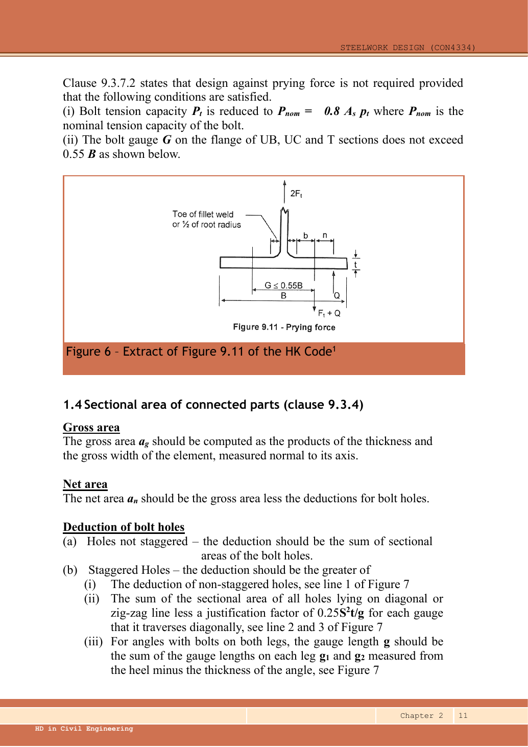
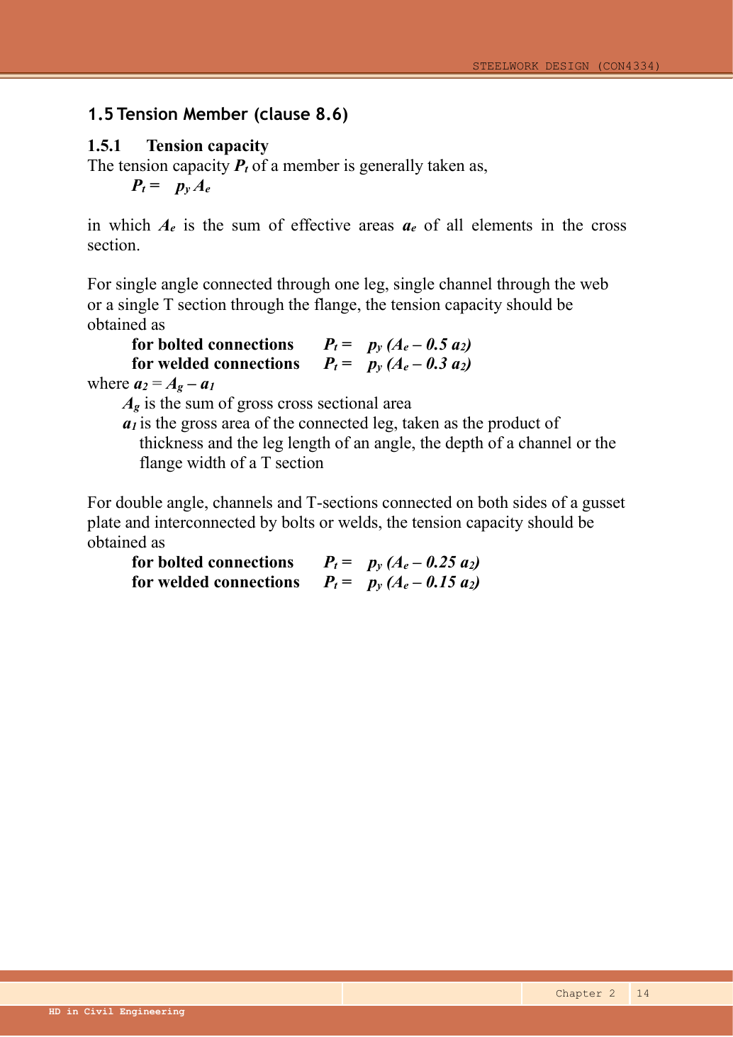
A transverse fracture line crosses TWO holes, one in each row. It does not cross all six holes on a half-splice. Effective area is the smaller of Ke times net area and gross area. The 24 mm main plate uses design strength 345 N/mm²; each 10 mm cover uses 355 N/mm².
With the centred joint, all the requested strength checks pass, and cover-plate tension governs. One extra point worth a line: the 35 mm side edge and 45 mm end distance meet the M27 minimum of 33.75 mm for rolled or gas-cut edges, but not the 47.25 mm needed for sheared or hand-flame-cut edges; the paper does not say how the plates are cut.