Assignment 1 Q1: storage-floor beams and an annotated connection sketch
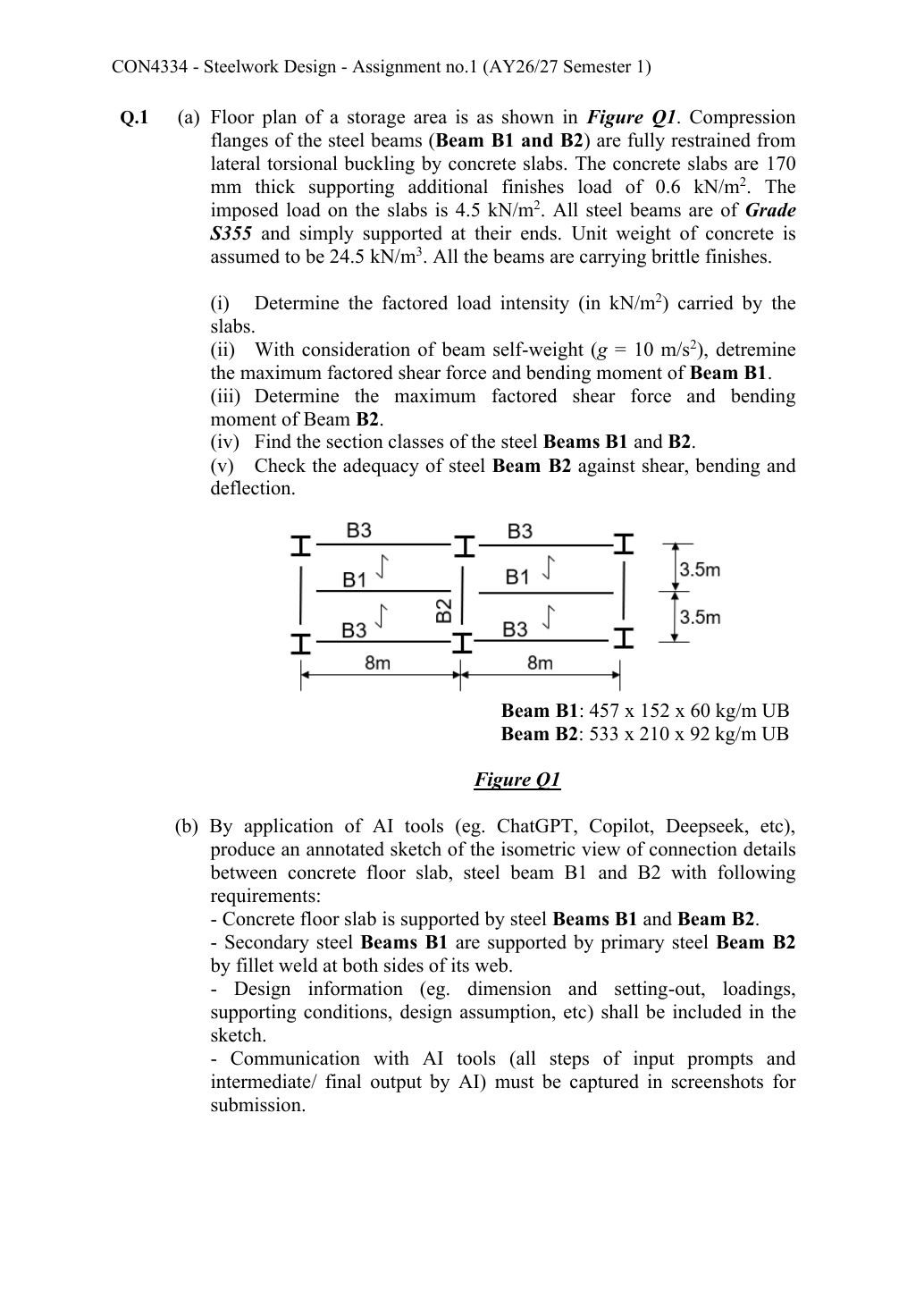
For the source storage-floor plan, find ultimate slab intensity, B1 and B2 maximum shear/moment, both section classes, and B2 shear/bending/deflection adequacy. Then produce the requested annotated isometric slab–B1–B2 web-weld connection sketch. S355 beams are simply supported and fully laterally restrained by concrete slabs, with brittle finishes.
Original source: Assignment/AY2627s 1-CON4334-Assignment 1.pdf — p. 1.
A given value comes from the question or diagram.
A lookup value comes from the named table.
A calculated value follows from the working.
Each assumption is stated where the calculation needs it.
Known information, diagram labels and unknowns
A safe beam can still sag too far
Check whether the beam displacement exceeds the permitted service limit.
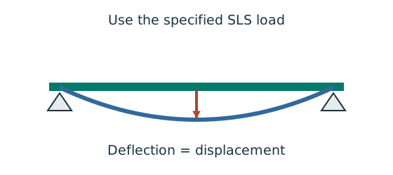
Prediction, then explanation. For the same UDL and stiffness, doubling span multiplies deflection by sixteen. Doubling I halves deflection.
Load bends each beam segment. The curvature accumulates along the span. Material stiffness E and geometric stiffness I resist that deformation.
Use w in N/mm, L in mm, E in N/mm² and I in mm⁴. The resulting midspan deflection is in mm.
Scope. The formula assumes a prismatic, simply supported, linear-elastic beam with full-span UDL. Use the stated service load and deflection limit.
Check and takeaway. A higher yield grade does not automatically increase E. Passing a strength check therefore does not prove acceptable deflection.
Vertical bending can trigger sideways motion
A beam has enough local bending resistance. Check whether its compression flange can move sideways and twist.
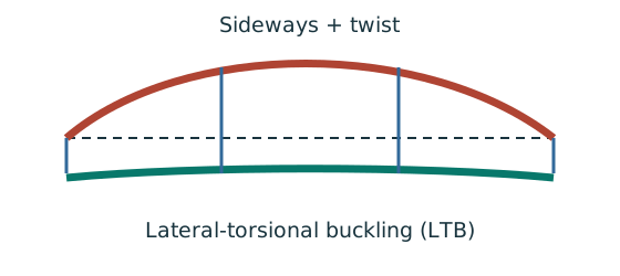
Prediction, then explanation. Adding a valid lateral restraint shortens a stability segment. It need not change the beam’s vertical reaction or moment diagram.
Identify the compressed flange and effective restraints. Calculate the specified slenderness, read buckling strength and compare resistance with the segment demand.
LE and ry use the same length unit. pb uses N/mm²; Sx uses mm³; Mb uses N·mm. mLT is dimensionless.
Scope. Use the specified section class, effective-length branch and loading condition. Load height alone does not prove a destabilizing case.
Check and takeaway. Removing a lateral restraint requires a new segment stability check. The old shorter-segment result cannot establish the longer segment’s adequacy.
Change the ruler, keep the quantity
A section table uses centimetres, but the strength calculation uses millimetres. The numbers must describe the same section.
Prediction, then explanation. Would every property increase by ten? No. The exponent determines how many factors of ten are needed.
First identify the physical quantity. Next convert each length factor. Keep force and length conversions separate when converting a moment.
Here n is the length exponent: 2 for area, 3 for section modulus and 4 for second moment of area.
Scope. Changing units changes neither the load nor the section. A conversion factor cannot repair a formula for the wrong physical quantity.
Check and takeaway. Illustration: . The fourth power belongs to the unit, not the number 2.
Apply the reasoning to this section’s data and conditions
| Input | Exact origin |
|---|---|
| Slab | Given thickness ; unit weight ; additional finish ; imposed . |
| Gravity | The question explicitly specifies the beam self-weight calculation using . Use this value rather than another default. |
| Given UB; Data File p.9 mass (nominal designation ). | |
| Given UB; Data File p.9 mass (nominal designation ). | |
| Restraints/finish | Given simple supports, full slab compression-flange lateral restraint and brittle finish. LTB is suppressed in this particular check. |
| Connection sketch | Part(b) explicitly calls for secondary B1 supported by primary B2 with fillet welds at both sides of B1’s web. No weld leg, length, cope size or connection plate detail is specified. |
Why this method applies
Use the same mechanism: A safe beam can still sag too far. For the same UDL and stiffness, doubling span multiplies deflection by sixteen. Doubling I halves deflection.
Follow one strip of floor
An area load must become a beam load before beam reactions can be calculated.
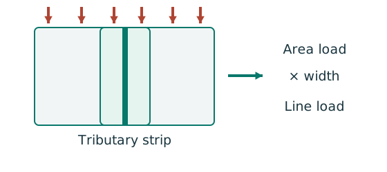
Prediction, then explanation. At fixed area load, twice the tributary width gives twice the line load. An end reaction remains a concentrated force.
Consider one metre along the beam. The associated floor area is b square metres. Multiply area load by that width.
q is area load in kN/m²; b is tributary width in m; w is line load in kN/m.
Scope. Determine b from slab spanning and supports. Add beam self-weight separately. A secondary-beam reaction is not automatically a UDL.
Check and takeaway. Illustration: . The width cancels one length unit.
Keep load categories separate
A floor carries permanent material and changing occupancy loads. Find the design load for the stated check.
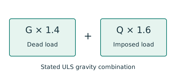
Prediction, then explanation. Increasing imposed load changes its own term. It does not change the dead-load factor or the steel stiffness.
First convert mass to weight where required. Next collect G and Q in compatible units. Apply the combination specified by the course problem.
G is characteristic dead load; Q is characteristic imposed load. Wu is the design load for this course gravity combination.
Scope. This combination is not universal. Use the specified service load for deflection and the stated factors for other standards or cases.
Check and takeaway. Illustration: G = 10 kN and Q = 5 kN give 22 kN. Factoring their sum by one guessed factor loses the distinction.
Apply the reasoning to this section’s data and conditions
Start at the slab, convert surface intensity to B1 line load using tributary width, and pass both B1 reactions into the middle of B2.
End-joint reactions from B3 occur at B2’s vertical supports and do not create additional B2 span bending in the simple model.
Strength and deflection use different load combinations.
(a)(i) Ultimate slab load intensity
Use the same mechanism: Keep load categories separate. Increasing imposed load changes its own term. It does not change the dead-load factor or the steel stiffness.
Apply the reasoning to this section’s data and conditions
Physical interpretation: Why dead and imposed loads stay separate
Keep permanent load and imposed load separate until their respective factors have been applied.
Sketch, not to scale; use the original dimensions.
- Include self-weight and permanent finishes in permanent load.
- Include the specified occupancy load in imposed load.
- For this course’s stated gravity combination: .
Remember: That ULS combination is not the imposed-load deflection load.
The extra finish is dead load; “brittle” controls the later deflection limit and does not change its load category.
Mechanism detailsFrom characteristic to design load
The complete mechanism is explained below.
Read each stage together with its stated conditions; playback and interaction are not required.
G is permanent load; Q is imposed load.
A surface load and a line load also have different units.
This illustration uses the course gravity case .
Other combinations in the original text retain their own factors.
- For illustrative , the separate load contributions show what changes when Q increases.
Do not carry this ULS total automatically into deflection.
Follow the stated SLS load case.
(a)(ii) B1 maximum factored shear and moment
Use the same mechanism: Follow one strip of floor. At fixed area load, twice the tributary width gives twice the line load. An end reaction remains a concentrated force.
Use the same mechanism: Keep load categories separate. Increasing imposed load changes its own term. It does not change the dead-load factor or the steel stiffness.
Balance the isolated beam
Find the two vertical reactions before calculating internal shear or moment.
Prediction, then explanation. Move the same load toward B. Reaction B increases because the load has a larger moment arm about A.
Take moments about A. Reaction A has zero lever arm there. Then use vertical force balance to find reaction A.
P, RA and RB are forces in kN. L is support spacing and a is load position, both in m.
Scope. These expressions describe one point load on a simply supported beam. Add other loads through equilibrium; keep their actual positions.
Check and takeaway. Illustration: P = 60 kN, L = 6 m and a = 2 m give RB = 20 kN and RA = 40 kN.
Apply the reasoning to this section’s data and conditions
One B1’s full factored load is .
However, its reaction on B2 is half of that,.
The numerical equality between this full load in and its maximum moment in is coincidental for .
The quantities and units remain different.
Mechanism detailsFollow the floor load in 3D
The complete mechanism is explained below.
Read each stage together with its stated conditions; playback and interaction are not required.
The floor carries pressure in .
The highlighted strip belongs to one secondary beam.
Multiply pressure by tributary width: .
The illustration uses .
- A primary beam receives the secondary beam reaction at their connection, not a new full-span UDL.
Trace reactions down to columns and foundations.
Count each loaded area once.
(a)(iii) B2 maximum factored shear and moment
Use the same mechanism: Follow one strip of floor. At fixed area load, twice the tributary width gives twice the line load. An end reaction remains a concentrated force.
Use the same mechanism: Keep load categories separate. Increasing imposed load changes its own term. It does not change the dead-load factor or the steel stiffness.
Use the same mechanism: Balance the isolated beam. Move the same load toward B. Reaction B increases because the load has a larger moment arm about A.
Apply the reasoning to this section’s data and conditions
Physical interpretation: How a floor load reaches a beam
Each beam collects the load from its own strip of floor.
Sketch, not to scale; use the original dimensions.
- Find the tributary width from the actual plan.
- Area load × tributary width gives load per beam length.
- A supporting beam receives the other beam’s end reaction.
Remember: A reaction becomes a point load, not automatically a UDL.
Do not apply / to again: it is already assembled from ultimate B1 reactions.
Only B2’s newly introduced self-weight is factored at this step.
Mechanism detailsFollow the floor load in 3D
The complete mechanism is explained below.
Read each stage together with its stated conditions; playback and interaction are not required.
The floor carries pressure in .
The highlighted strip belongs to one secondary beam.
Multiply pressure by tributary width: .
The illustration uses .
- A primary beam receives the secondary beam reaction at their connection, not a new full-span UDL.
Trace reactions down to columns and foundations.
Count each loaded area once.
(a)(iv) Both section classes
Find which plate buckles first
Before using plastic bending resistance, check whether the flange and web can sustain the required stress distribution.
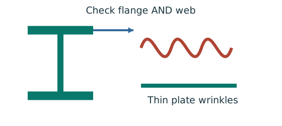
Prediction, then explanation. At fixed width, a thinner plate has a larger width-to-thickness ratio. Local buckling then becomes more restrictive.
Calculate the flange and web ratios separately. Compare each with the limits for its stress condition. The worse class governs.
py is the design yield strength in N/mm². ε is a dimensionless scale used in the supplied classification limits.
Scope. Pure bending and uniform compression use different web limits. Class 2 allows plastic resistance but not the Class 1 rotation capability.
Check and takeaway. A Class 1 web and Class 2 flange give a Class 2 section. Do not average the class numbers.
Apply the reasoning to this section’s data and conditions
Physical interpretation: A thin part can wrinkle first
A thin plate may wrinkle before the whole steel member reaches its intended resistance.
Sketch, not to scale; use the original dimensions.
- Check flange and web slenderness using their own definitions.
- Compare each ratio with the correct class limits.
- The element with the more restrictive class determines the section class.
Remember: Bending limits and uniform-compression limits are different.
Read each exact UB row.
The weakest compression element governs.
Pure bending has a web compression/tension stress gradient.
Therefore, use the bending web limit for Class 1, not the uniform-compression column limit.
Lookup: Data File pp.9–10, exact UB row.
Dimensions on p.9; properties on p.10.
is overall depth.
is the clear web depth between root fillets, not the nominal designation.
| Property | Lookup value / conversion |
|---|---|
| Dimensions | D454.6, web t 8.1, flange T13.3, root r 10.2, clear d 407.6, all |
| Local ratios | ;。 |
| Major-axis properties | ; ; . |
| LTB properties | ; ; torsional index . |
Lookup: Data File pp.9–10, exact UB row.
Dimensions on p.9; properties on p.10.
is overall depth.
is the clear web depth between root fillets, not the nominal designation.
| Property | Lookup value / conversion |
|---|---|
| Dimensions | D533.1, web t 10.1, flange T15.6, root r 12.7, clear d 476.5, all |
| Local ratios | ;。 |
| Major-axis properties | ; ; . |
| LTB properties | ; ; torsional index . |
Both sections are Class 1, and both flange thicknesses lie in the range.
Therefore, use .
Both web ratios are also below .
Therefore, the course trigger does not require a separate shear-buckling check.
Mechanism detailsWhy thin elements buckle locally
The complete mechanism is explained below.
Read each stage together with its stated conditions; playback and interaction are not required.
- The flange outstand and web have different widths, thicknesses and edge support conditions.
- A thinner plate can wrinkle locally before the complete member loses stability.
Class 1 allows plastic rotation.
Class 2 reaches plastic resistance.
Class 3 reaches elastic resistance.
Class 4 requires effective properties.
Check every relevant compression element with the supplied limits and stress distribution.
The deformation shown is qualitative.
(a)(v) B2 strength and brittle-finish deflection
The web carries the shear check
Compare the applied shear with the resistance of the prescribed shear area.
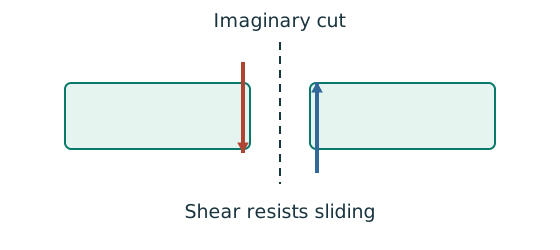
Prediction, then explanation. At fixed design strength and depth, increasing web thickness increases this shear resistance.
Calculate the prescribed shear area. Multiply by the design shear stress from the course rule. Then compare matching force units.
D is overall depth; t is web thickness, in mm. Av uses mm². py uses N/mm², giving Vc in N.
Scope. Apply this area definition to the stated rolled section. Check web slenderness separately. The factor 0.6 is the low-shear threshold, not this resistance coefficient.
Check and takeaway. A shear pass alone does not prove bending, deflection or local support-web adequacy.
Internal tension and compression resist moment
Find which section resistance applies before comparing it with the moment demand.
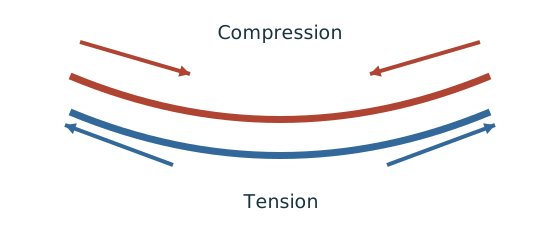
Prediction, then explanation. A larger appropriate section modulus raises resistance at fixed strength. Local plate buckling can restrict the usable modulus.
Classify the section first. At low shear, use the elastic expression for Class 3 or the prescribed capped plastic expression for Classes 1 and 2.
py uses N/mm². S is plastic modulus and Z is elastic modulus, both in mm³. Mc then uses N·mm.
Scope. This is section resistance, not whole-member LTB resistance. High shear and Class 4 require their appropriate treatment.
Check and takeaway. Selecting the larger of the two capped terms defeats the cap. Use their minimum.
Shear and bending share the web
Decide whether the unreduced bending resistance remains applicable at the section being checked.
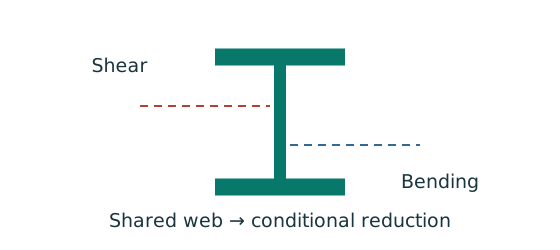
Prediction, then explanation. Raising shear beyond the specified threshold can reduce available bending resistance. A distant maximum shear is not the coexistent shear.
Find the moment-check position. Evaluate the shear there. Compare it with the low-shear threshold before selecting the resistance expression.
V is shear at the checked section; Vc is its shear resistance. Both use the same force unit.
Scope. Above the threshold, use the supplied reduction expression. The threshold itself is not a substitute resistance formula.
Check and takeaway. If the maximum shear anywhere is below the threshold, all sections satisfy that low-shear condition. Otherwise check the actual positions.
Apply the reasoning to this section’s data and conditions
Physical interpretation: How much does the beam sag?
Strength asks whether it fails; deflection asks how far it moves.
Sketch, not to scale; use the original dimensions.
- Use the serviceability load case specified by the course question.
- Choose the expression matching the support and load positions.
- Use consistent units for load, length, E and I.
Remember: The largest deflection is not always at midspan.
The slab fully restrains the compression flange by the question’s explicit assumption.
Therefore, use the cross-section bending resistance.
Do not claim that this assumption proves the weld detail in(b) supplies a rigid moment connection.
B2 is adequate for the requested shear, bending and imposed-load deflection checks.
This part does not supply the contact dimensions needed for separate support web-bearing detail checks.
Mechanism detailsSee shear in the web
The complete mechanism is explained below.
Read each stage together with its stated conditions; playback and interaction are not required.
- Internal shear keeps the two sides of the cut in vertical equilibrium.
For the course’s common I-section case, the web provides the principal shear area.
Use the specified definition.
- A slender web may require a different shear-buckling route before a simple shear-resistance formula is used.
Use where applicable in the course.
Convert N to kN before comparing with design shear.
(b) Completed annotated isometric teaching sketch
Use the same mechanism: Follow one strip of floor. At fixed area load, twice the tributary width gives twice the line load. An end reaction remains a concentrated force.
Use the same mechanism: Balance the isolated beam. Move the same load toward B. Reaction B increases because the load has a larger moment arm about A.
The weld resists through its throat
Convert a visible fillet leg into resistance per effective length.
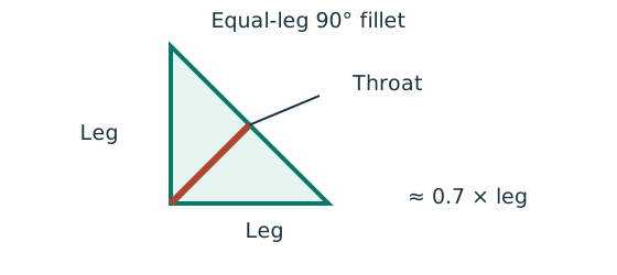
Prediction, then explanation. At fixed weld strength, doubling the leg doubles throat and line resistance in this model. Detailing limits can prevent that choice.
For the course right-angle equal-leg fillet, take throat as 0.7 times leg. Multiply throat area per unit length by weld strength.
s and a are leg and throat in mm. pw is weld strength in N/mm². qcap is resistance in kN/mm.
Scope. Use effective length, the correct steel/electrode strength and permitted leg limits. Full-penetration butt welds use a different model.
Check and takeaway. Illustration: a 6 mm leg at 250 N/mm² gives .
Apply the reasoning to this section’s data and conditions
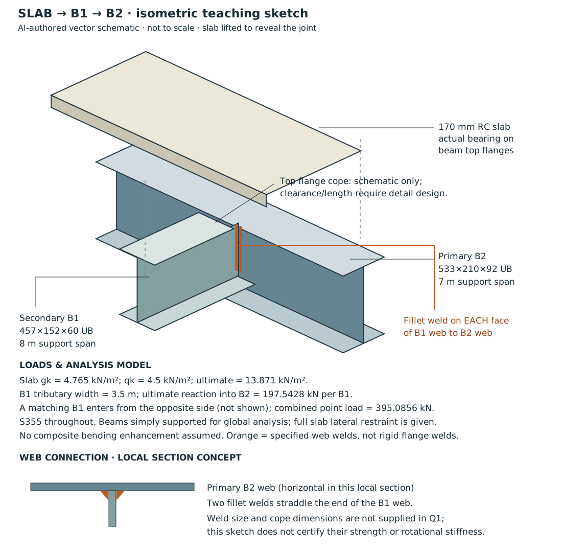
Selectable equivalents of the diagram labels and formulas: slab thickness ; primary beam B2 is UB, with a support-to-support span of ; secondary beam B1 is UB, with a support-to-support span of .
For the slab, , , with ultimate load .
The tributary width of B1 is .
Each B1 delivers an ultimate reaction to B2 of .
Together with the B1 on the opposite side, which is not drawn, the total point load is .
All steel is S355.
The simply supported overall model and the fully restrained condition given in the question are unchanged.
No increase in bending resistance from composite action is assumed.
These are selectable equivalents of values already labelled in the drawing, not additional question data.
The drawing shows the requested slab, primary B2 and a perpendicular secondary B1.
A matching B1 meets the far side in the floor plan.
It is identified in the annotations to keep the joint visible.
Orange marks the two fillets on the faces of B1’s web.
The slab is lifted only for visibility; in the actual assembly it bears on the beam top flanges.
A conceptual top-flange cope is identified to avoid drawing solid steel members unrealistically through each other.
The simple-support global model requires appropriate rotational behaviour in the actual connection.
Welding both web faces does not, by itself, establish a rigid beam-end moment connection.
The sketch deliberately makes no unsupported weld-size or cope-dimension claim.
Those are connection-design inputs not provided in Q1.
The supplied beam sizes, spans, slab depth, loads and assumptions are fully annotated.
AI-process evidence required by the assignment: the SVG above is an actual AI-authored output for this learning website.
It is not a historical screenshot record of a student’s conversation.
For an assessed submission, capture your own complete prompt/output sequence, including revisions.
Do not fabricate screenshots or present suggested prompts as past interactions.
| An illustrative prompt sequence for learning | What to verify in the resulting output |
|---|---|
| “Create an isometric schematic from this exact floor plan: slab; B1 spanning into B2 spanning ; two fillet welds on the B1 web; include only the provided dimensions.” | Correct beam orientation, both web welds, real slab support and no invented weld leg. |
| “Add the independently checked loads: , ; reaction from each B1 , combining at B2 midspan to give . Identify the exploded slab display and any conceptual cope.” | Units, centroid/load positions and given-versus-assumed labels match the calculation. |
| “Audit the sketch for crossed solid flanges, absent welds, unsupported connection dimensions and an unjustified rigid-joint claim; revise and list changes.” | Keep both the flawed intermediate image and the corrected output in your genuine evidence trail. |
These prompts are clearly labelled illustrations, not a fabricated transcript.
The completed vector can be opened locally and printed without online services.
The assignment’s student-specific screenshot trail remains separate evidence that this source package cannot supply.
Mechanism detailsFollow the floor load in 3D
The complete mechanism is explained below.
Read each stage together with its stated conditions; playback and interaction are not required.
The floor carries pressure in .
The highlighted strip belongs to one secondary beam.
Multiply pressure by tributary width: .
The illustration uses .
- A primary beam receives the secondary beam reaction at their connection, not a new full-span UDL.
Trace reactions down to columns and foundations.
Count each loaded area once.
Result and concise exam wording
Use the same mechanism: A safe beam can still sag too far. For the same UDL and stiffness, doubling span multiplies deflection by sixteen. Doubling I halves deflection.
A cut reveals the internal actions
Find where the beam moment is largest. A large load arrow alone does not locate that point.
Prediction, then explanation. Under a uniform downward load, shear falls steadily. Moment reaches a stationary value where shear becomes zero.
Balance the forces on the cut piece to get V. Balance their moments about the cut to get M. Evaluate each load region separately.
x and L use m; w uses kN/m; V uses kN; M uses kN·m. These lines apply before any point load.
Scope. A point load adds a shear jump. A concentrated couple adds a moment jump. Check load points, supports and overhang roots too.
Check and takeaway. A UDL gives a sloping shear line and a curved moment line. A flat moment diagram therefore cannot represent a loaded UDL region.
Use the same mechanism: Internal tension and compression resist moment. A larger appropriate section modulus raises resistance at fixed strength. Local plate buckling can restrict the usable modulus.
Apply the reasoning to this section’s data and conditions
(a) Ultimate area load .
B1: , , .
B2: plus uniformly distributed load ,, .
Both are Class 1, .
B2 passes shear and low-shear bending; imposed-load deflection . (b) An annotated local isometric SVG is provided.
Connection dimensions absent from the source and a student-specific screenshot history have not been invented.
Misconceptions and checks
Use the same mechanism: A safe beam can still sag too far. For the same UDL and stiffness, doubling span multiplies deflection by sixteen. Doubling I halves deflection.
Apply the reasoning to this section’s data and conditions
- Do not use as B2’s span.
- Do not send one B1’s full load as its end reaction.
- Do not double-factor B1 reactions on B2.
- Do not use in the imposed-only deflection.
- Do not fabricate AI-process screenshot evidence.
How the method transfers to a new variant
Use the same mechanism: Find which plate buckles first. At fixed width, a thinner plate has a larger width-to-thickness ratio. Local buckling then becomes more restrictive.
Use the same mechanism: A safe beam can still sag too far. For the same UDL and stiffness, doubling span multiplies deflection by sixteen. Doubling I halves deflection.
Use the same mechanism: Follow one strip of floor. At fixed area load, twice the tributary width gives twice the line load. An end reaction remains a concentrated force.
Apply the reasoning to this section’s data and conditions
- Read slab span direction and tributary width.
- Calculate characteristic surface loads, then factored intensity.
- Include each beam’s self-weight once.
- Transfer reactions through the floor hierarchy.
- Classify and run the requested strength/serviceability checks.
- Annotate the sketch with verified values and clearly identify conceptual details.
Prediction with explained answer
Use the same mechanism: A safe beam can still sag too far. For the same UDL and stiffness, doubling span multiplies deflection by sixteen. Doubling I halves deflection.
Apply the reasoning to this section’s data and conditions
Prediction and explained answer.
Invented variant: only one of the two B1 beams meets B2 at midspan, with all other values unchanged.
Find B2 maximum moment and imposed deflection.
Answer and reasoning
Central becomes .
B2 moment: Central imposed load halves to , giving B2 self-weight is unchanged.
Therefore, the total moment used for the strength check does not halve exactly.
Mechanism detailsBalance reactions and moments
The complete mechanism is explained below.
Read each stage together with its stated conditions; playback and interaction are not required.
This demonstrator is a simply supported 6 m beam with a 60 kN point load.
It is not the page’s original loading diagram.
.
Moving the load towards B increases .
.
The two upward reactions must sum to P.
With the load at midspan, .
End couples, UDLs and overhangs require their own equilibrium terms.