Tutorial 2 Q4: combined bolt shear and tension
Use the approximate method to check twelve Grade 8.8 M20 bolts in the bracket carrying characteristic dead and imposed at eccentricity .
Original source: LectureNotes/Ch 2_Connection.pdf — p. 45, p. 47.
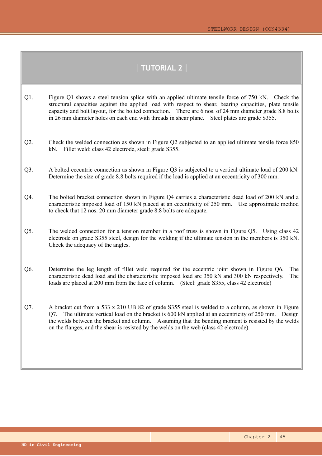
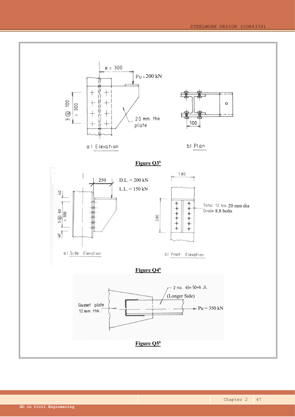
A given value comes from the question or diagram.
A lookup value comes from the named table.
A calculated value follows from the working.
Each assumption is stated where the calculation needs it.
Known information, diagram labels and unknowns
An eccentric bracket pulls bolts differently
An out-of-plane moment rotates the bracket about the stated pivot. Determine the bolt tension pattern.
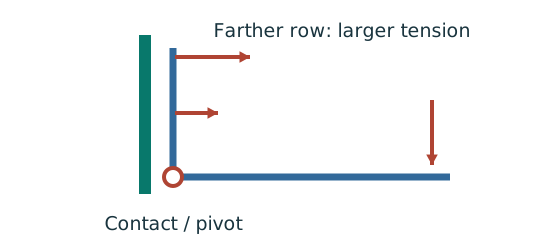
Prediction, then explanation. For unchanged geometry, doubling the applied moment doubles the modelled bolt tensions. Changing the pivot changes the distribution.
Use compatibility to relate tension to distance. Moment equilibrium then determines the proportionality factor.
M is moment in kN·mm. yi is distance from the stated pivot in mm. Ft,i is tension in kN.
Scope. Apply only to the stated active bolt set and pivot model. Flexible plates can create prying; use the supplied assumptions and resistance definitions.
Check and takeaway. A bolt’s lever arm is measured from the pivot used in the equation. It is not automatically its distance from the group centroid.
Keep load categories separate
A floor carries permanent material and changing occupancy loads. Find the design load for the stated check.
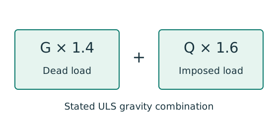
Prediction, then explanation. Increasing imposed load changes its own term. It does not change the dead-load factor or the steel stiffness.
First convert mass to weight where required. Next collect G and Q in compatible units. Apply the combination specified by the course problem.
G is characteristic dead load; Q is characteristic imposed load. Wu is the design load for this course gravity combination.
Scope. This combination is not universal. Use the specified service load for deflection and the stated factors for other standards or cases.
Check and takeaway. Illustration: G = 10 kN and Q = 5 kN give 22 kN. Factoring their sum by one guessed factor loses the distinction.
Apply the reasoning to this section’s data and conditions
| Input | Origin/model |
|---|---|
| Loads | Given characteristic /; must be factored. |
| Approximate pivot | Follow the lecturer's lowest-bolt-row rotation model from connection example 4. Row distances are , with two bolts per row. |
| Fastener properties | M20 ,Grade 8.8 , ; nominal tension resistance . |
| Shear distribution | Equal direct shear over bolts; tension proportional to distance from the assumed pivot. |
Why this method applies
Add force components at each bolt
An in-plane load acts away from the bolt-group centre. Find the largest resultant bolt force.
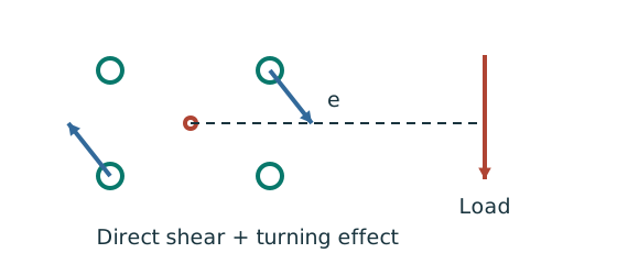
Prediction, then explanation. At fixed force, increasing eccentricity increases the moment component. Its direction differs between bolts.
Locate the bolt-group centre and coordinates. Add horizontal components together and vertical components together before finding each resultant.
e, xi and yi use mm; J uses mm². With M in kN·mm, each moment-force component is in kN.
Scope. These expressions use the stated elastic, equal-bolt in-plane model. Out-of-plane tension and prying require another model.
Check and takeaway. Do not add force magnitudes before resolving directions. Two perpendicular forces of 3 and 4 kN give 5 kN, not 7 kN.
Test every possible fracture cut
Find the remaining steel area across a candidate tension-failure path.
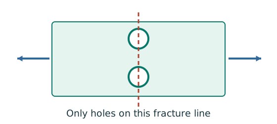
Prediction, then explanation. At fixed plate size, larger holes reduce the straight-path net area. A diagonal path needs its own stagger correction.
Subtract the hole widths crossed by the path, then multiply by thickness. Compare all plausible paths using the applicable course rule.
An is net area in mm²; b is plate width; d₀ is hole diameter; t is thickness, all in mm. n counts holes on this straight path.
Scope. This expression is for a straight cut. Effective area can require further shear-lag rules. Gross, net and effective areas must remain distinct.
Check and takeaway. Use the hole diameter, not the bolt diameter, when removing missing steel. The plate contains a hole, not solid steel around the bolt shank.
Two simultaneous actions use one component
Check a component that carries shear and tension, or compression and bending, at the same time.
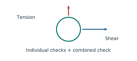
Prediction, then explanation. At fixed resistances, increasing one demand increases its utilisation. The permitted sum is not always one.
First apply the individual checks. Next use the exact combined equation and its definitions. Keep demands from the same load case.
This is the course bolt interaction rule. Fs and Ft are bolt demands; Ps and Pnom are their specified resistance denominators.
Scope. The 1.4 limit and nominal tension denominator do not apply to column equations. Their limits and moment definitions are separate.
Check and takeaway. A sum above one can pass this bolt rule while still needing individual checks. A pass must name the actual equation used.
Apply the reasoning to this section’s data and conditions
The load acts out of the bolt-group plane and tends to peel the top of the plate away.
The approximate method makes upper bolts carry more tension while every bolt carries direct shear.
Even if each individual action is less than its own resistance, the combined interaction may fail.
The lecturer's method is in the “Lecturer's answer” section.
Therefore, the wording “check that ... adequate” must not override the arithmetic.
1. Ultimate force, moment and maximum bolt tension
Use the same mechanism: An eccentric bracket pulls bolts differently. For unchanged geometry, doubling the applied moment doubles the modelled bolt tensions. Changing the pivot changes the distribution.
Apply the reasoning to this section’s data and conditions
Physical interpretation: Why the top bolt row is pulled hardest
The bracket tries to peel away from the support about the assumed contact line.
Sketch, not to scale; use the original dimensions.
- Use the rotation/contact line assumed by the course model.
- Measure each bolt row’s distance from that line.
- Check maximum tension, direct shear and their interaction.
Remember: A row at the pivot can still carry direct shear.
The factor counts the two bolts at each row.
The bottom row contributes zero to the assumed moment-resisting tension sum but still carries direct shear.
Mechanism detailsOut-of-plane bolt tension and prying
The complete mechanism is explained below.
Read each stage together with its stated conditions; playback and interaction are not required.
- A bracket moment can create compression at the plate contact and tension in the bolt rows.
- The original assumed pivot/compression line determines each row distance.
Under the elastic row model, a farther tension row attracts more tension.
Direct shear may act simultaneously.
Flexible plates can add prying force.
Use nominal tension and interaction rules exactly as specified by the course.
2. Direct shear per bolt
Count cuts through each loaded bolt
Find how many shear planes transfer the force through one side of the connection.
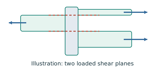
Prediction, then explanation. For equal sharing and unchanged bolt area, two active planes provide twice one plane’s shear resistance.
Select the area at the actual shear plane. Multiply by bolt shear strength. Count only the bolts and planes in the same transfer stage.
ps is bolt shear strength in N/mm²; As is the appropriate area in mm². nb counts bolts; ns counts equally loaded shear planes.
Scope. Use the thread area when threads cross the plane as required. Check bearing, plate failure and detailing separately.
Check and takeaway. Both halves of a butt splice carry the full transmitted force in sequence. Counting both halves together would double the apparent resistance.
Apply the reasoning to this section’s data and conditions
Mechanism detailsCount the bolt shear planes
The complete mechanism is explained below.
Read each stage together with its stated conditions; playback and interaction are not required.
- Load must cross an interface between the connected plates.
- A lap joint gives one shear plane through a bolt.
A symmetric double-cover joint may provide two shear planes.
Count load-transfer interfaces, not just visible plates.
Use the source’s area and shear strength.
Then check bearing, plate resistance and detailing separately.
3. Check the simultaneous actions on a top bolt
Use the same mechanism: Two simultaneous actions use one component. At fixed resistances, increasing one demand increases its utilisation. The permitted sum is not always one.
Apply the reasoning to this section’s data and conditions
Physical interpretation: Two passing checks may still interact
One bolt is doing two jobs at the same time.
Sketch, not to scale; use the original dimensions.
- Check shear on its own and tension on its own.
- Calculate the course’s combined-action expression.
- Apply its own limit, not a limit borrowed from columns.
Remember: The supplied bolt interaction limit of 1.4 does not replace the individual checks.
The course interaction limit is , as shown in Ch 2 p.10 and Example 4 p.28.
Do not automatically use a limit of for every interaction equation.
Both individual ratios are also below .
Therefore, the requested approximate bolt strength check passes.
The normalised combined utilisation is , a narrow margin.
Gauge and supporting-flange dimensions are not supplied sufficiently to prove the no-prying condition or all bearing checks.
The result is conditional on the course nominal-tension model being applicable.
The assumed rotation point is a modelling choice.
If placed instead at the bottom contact edge below the lowest row, row distances become ,.
Maximum tension becomes , with interaction approximately .
This solution consistently uses the lecturer's lowest-bolt-row model.
Mechanism detailsCombined actions share resistance
The complete mechanism is explained below.
Read each stage together with its stated conditions; playback and interaction are not required.
- Shear and tension, or compression and bending, must refer to the same bolt or checked section.
- Divide every action by the resistance prescribed for that term.
The bars illustrate a linear sum only.
Bolt interaction can have a different limit and individual checks; retain the original expression.
A pass in one interaction does not prove all failure modes pass.
The complete calculation below checks the specified interaction and the separate failure modes.
Lecturer's answer
| Item | Lecturer's value |
|---|---|
| Design load | |
| Single shear / tension capacity | , |
| Top bolt tension | |
| Shear per bolt | |
| Combined check |
Conclusion: The bolts are adequate (approximate method, combined value 1.368 ≤ 1.4).
Source: Lecturer's tutorial solution, Ch 2, p. 5.
Result and concise exam wording
Use the same mechanism: An eccentric bracket pulls bolts differently. For unchanged geometry, doubling the applied moment doubles the modelled bolt tensions. Changing the pivot changes the distribution.
Use the same mechanism: Two simultaneous actions use one component. At fixed resistances, increasing one demand increases its utilisation. The permitted sum is not always one.
Apply the reasoning to this section’s data and conditions
, .
Lowest-row rotation point: ,.
.
M20 , .
Individual checks pass; interaction .
The given bolts satisfy the requested approximate shear/tension model.
No-prying and bearing applicability still depends on unprovided support-detail information.
Misconceptions and checks
Use the same mechanism: Count cuts through each loaded bolt. For equal sharing and unchanged bolt area, two active planes provide twice one plane’s shear resistance.
Apply the reasoning to this section’s data and conditions
- Do not read “adequate” in the prompt as a required conclusion.
- Use twelve bolts for direct shear but the row-distance sum for tension.
- Do not compare only separate shear and tension results.
- A larger bolt requires new hole, spacing, edge and bearing checks.
How the method transfers to a new variant
Use the same mechanism: Add force components at each bolt. At fixed force, increasing eccentricity increases the moment component. Its direction differs between bolts.
Use the same mechanism: An eccentric bracket pulls bolts differently. For unchanged geometry, doubling the applied moment doubles the modelled bolt tensions. Changing the pivot changes the distribution.
The weld resists through its throat
Convert a visible fillet leg into resistance per effective length.
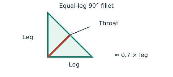
Prediction, then explanation. At fixed weld strength, doubling the leg doubles throat and line resistance in this model. Detailing limits can prevent that choice.
For the course right-angle equal-leg fillet, take throat as 0.7 times leg. Multiply throat area per unit length by weld strength.
s and a are leg and throat in mm. pw is weld strength in N/mm². qcap is resistance in kN/mm.
Scope. Use effective length, the correct steel/electrode strength and permitted leg limits. Full-penetration butt welds use a different model.
Check and takeaway. Illustration: a 6 mm leg at 250 N/mm² gives .
Apply the reasoning to this section’s data and conditions
- Identify the force path and whether the joint is concentric, in-plane eccentric or out-of-plane eccentric.
Read all dimensions from the relevant view.
Do not measure drawing scale.
- Distinguish characteristic from ultimate loads and factor only when needed.
- Calculate demand per fastener/weld with the appropriate equilibrium model.
- Check all requested resistances and detailing conditions separately.
- State whether the given detail passes, fails, or remains conditional on missing data.
Prediction with explained answer
Use the same mechanism: An eccentric bracket pulls bolts differently. For unchanged geometry, doubling the applied moment doubles the modelled bolt tensions. Changing the pivot changes the distribution.
Follow contact pressure into the plate
The bolt may survive shear while the connected plate deforms or tears near the hole.
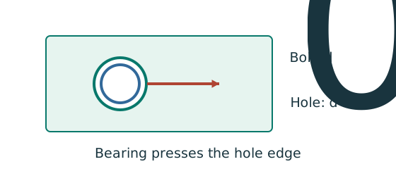
Prediction, then explanation. At fixed geometry and strength, a thicker plate raises plate resistance. Moving a hole too near the end can still govern.
Calculate every bound required by the supplied rule. The smallest applicable bound limits the connection at that layer.
pbs is the applicable bearing strength in N/mm²; d is nominal bolt diameter in mm; t is plate thickness in mm.
Scope. This diameter term alone is not the complete check. End-distance and clear-ligament limits, bolt bearing and each connected layer also matter.
Check and takeaway. Two covers and one main plate do not necessarily have the same thickness or strength. Compare the actual force share in each layer.
Use the same mechanism: Test every possible fracture cut. At fixed plate size, larger holes reduce the straight-path net area. A diagonal path needs its own stagger correction.
Apply the reasoning to this section’s data and conditions
Prediction and explained answer.
Invented variant: with all geometry and the characteristic load ratio unchanged, what is the largest overall load multiplier that passes this interaction?
Answer and reasoning
The interaction scales linearly with load.
Its maximum multiplier=
Corresponding ultimate load=.
Separate tension allows and shear allows , so combined action controls.
This concerns the approximate bolt checks only and does not establish missing plate/bearing/no-prying conditions.
Mechanism detailsOut-of-plane bolt tension and prying
The complete mechanism is explained below.
Read each stage together with its stated conditions; playback and interaction are not required.
- A bracket moment can create compression at the plate contact and tension in the bolt rows.
- The original assumed pivot/compression line determines each row distance.
Under the elastic row model, a farther tension row attracts more tension.
Direct shear may act simultaneously.
Flexible plates can add prying force.
Use nominal tension and interaction rules exactly as specified by the course.