Tutorial 2 Q2: welded splice strength and minimum-leg correction
Check the ultimate tension splice in FigureQ2. Steel is S355, electrode Class 42, and the drawing specifies fillet welds, cover plates and main plates.
Original source: LectureNotes/Ch 2_Connection.pdf — p. 45, p. 46.
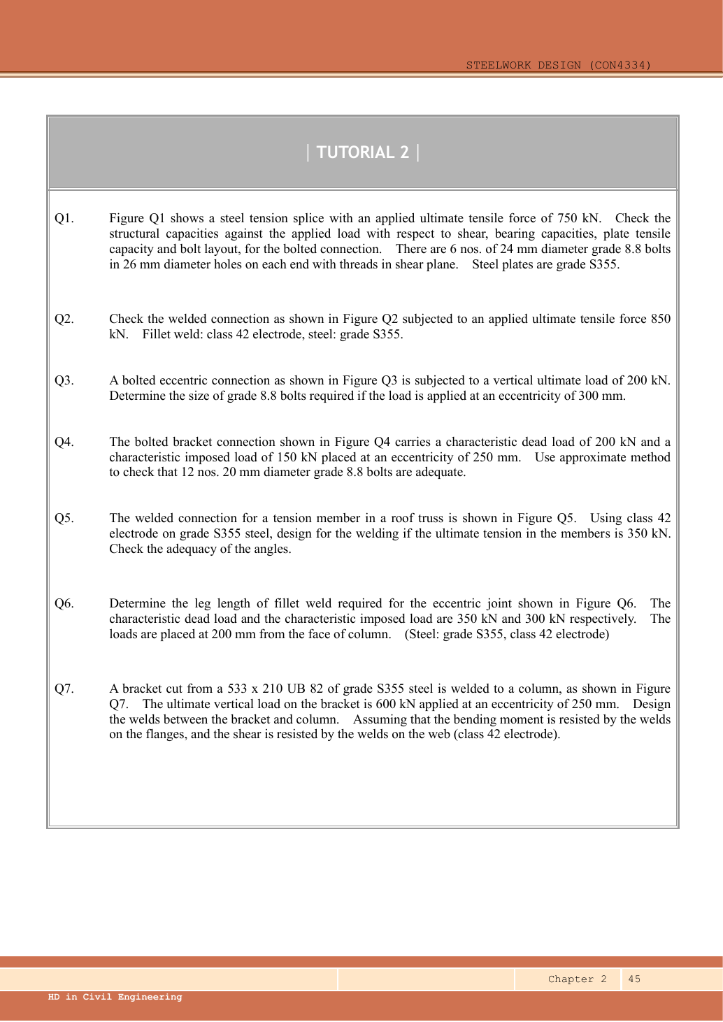
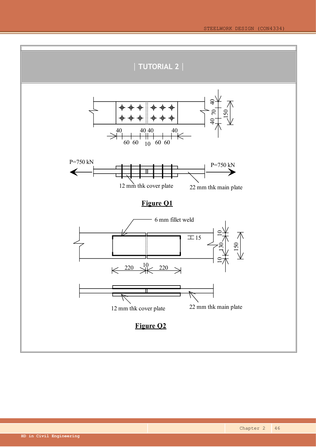
A given value comes from the question or diagram.
A lookup value comes from the named table.
A calculated value follows from the working.
Each assumption is stated where the calculation needs it.
Known information, diagram labels and unknowns
The weld resists through its throat
Convert a visible fillet leg into resistance per effective length.
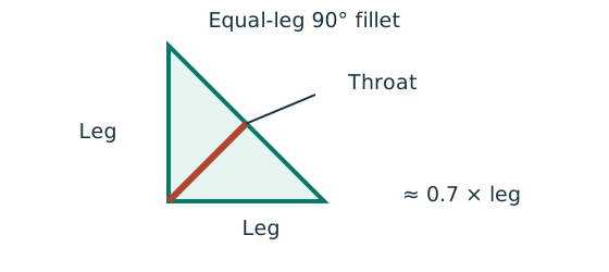
Prediction, then explanation. At fixed weld strength, doubling the leg doubles throat and line resistance in this model. Detailing limits can prevent that choice.
For the course right-angle equal-leg fillet, take throat as 0.7 times leg. Multiply throat area per unit length by weld strength.
s and a are leg and throat in mm. pw is weld strength in N/mm². qcap is resistance in kN/mm.
Scope. Use effective length, the correct steel/electrode strength and permitted leg limits. Full-penetration butt welds use a different model.
Check and takeaway. Illustration: a 6 mm leg at 250 N/mm² gives .
A table value has conditions
Find a design property without mixing a row, column or standard from a different case.
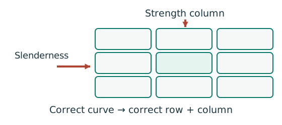
Prediction, then explanation. A different flange thickness can select a lower design strength even when the steel grade name remains unchanged.
Match the complete section designation. Read the relevant axis and unit. For strength tables, select material, thickness and curve before interpolating.
Given values come from the question. Lookup values come from a named table. Assumed values require an explicit condition.
Scope. A missing row or omitted restraint cannot be recovered from a schematic’s scale. Keep the result conditional when required data are absent.
Check and takeaway. Record the table, row, column and unit beside the substitution. That makes a later check possible.
Apply the reasoning to this section’s data and conditions
| Input | How it is used |
|---|---|
| Parallel runs | Each cover has two longitudinal side welds on each half; with two covers there are four load-transfer runs per half. |
| Length | Each run has physical length . Do not use as one effective run. |
| Material | The original website summary writes weld strength as , while the calculation below uses . This explanation follows the calculation notation. S355/Class 42 weld strength . Main-plate thickness , giving ; cover-plate thickness , giving . |
| Detailing | Thicker joined part selects minimum from Ch 2 Table 9.1. Cover edge permits at most by . |
Why this method applies
Test every possible fracture cut
Find the remaining steel area across a candidate tension-failure path.
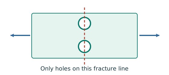
Prediction, then explanation. At fixed plate size, larger holes reduce the straight-path net area. A diagonal path needs its own stagger correction.
Subtract the hole widths crossed by the path, then multiply by thickness. Compare all plausible paths using the applicable course rule.
An is net area in mm²; b is plate width; d₀ is hole diameter; t is thickness, all in mm. n counts holes on this straight path.
Scope. This expression is for a straight cut. Effective area can require further shear-lag rules. Gross, net and effective areas must remain distinct.
Check and takeaway. Use the hole diameter, not the bolt diameter, when removing missing steel. The plate contains a hole, not solid steel around the bolt shank.
Use the same mechanism: The weld resists through its throat. At fixed weld strength, doubling the leg doubles throat and line resistance in this model. Detailing limits can prevent that choice.
Apply the reasoning to this section’s data and conditions
The two splice halves each transfer .
Sum the four parallel longitudinal runs within one half.
Start/end deductions apply to each run.
Check the main and cover plate tensile capacities, then examine weld-size and return detailing independently.
Short corner returns are not needed as extra strength in this conservative longitudinal-run model.
1. Calculate the drawn weld resistance
Use the same mechanism: The weld resists through its throat. At fixed weld strength, doubling the leg doubles throat and line resistance in this model. Detailing limits can prevent that choice.
Apply the reasoning to this section’s data and conditions
Physical interpretation: Why the weld throat is smaller than its leg
The shortest cut through the weld is thinner than the outside leg.
Sketch, not to scale; use the original dimensions.
- For the stated equal-leg 90° fillet, throat is approximately 0.7 × leg.
- Multiply throat area by the matching weld design strength.
- For force per length, use a one-millimetre weld strip.
Remember: Choose strength from both the steel grade and electrode class.
Adding both left and right halves would double-count resistance in series.
Mechanism detailsFrom fillet leg to effective throat
The complete mechanism is explained below.
Read each stage together with its stated conditions; playback and interaction are not required.
- An equal-leg fillet between perpendicular plates has an approximately right-triangular section.
For this geometry, throat .
It is shorter than the leg.
Effective resisting area = .
With here, capacity per length is .
- Use the course end allowances, minimum size and length rules; increasing the geometric length alone does not resolve every detailing check.
2. Plate tensile capacities
Follow tension through the intact plate
Check a plate region without bolt holes under the stated axial tension model.
Prediction, then explanation. For unchanged strength and uniform stress, doubling width doubles the area and its yield resistance.
Calculate the resisting area. Multiply by the applicable design strength. Compare that resistance with the force carried by this plate.
b and t use mm; A uses mm²; py uses N/mm². The product gives resistance in N.
Scope. This simple expression does not include holes, shear lag, eccentric bending or other required connection checks.
Check and takeaway. If two identical covers share the load symmetrically, each carries half. The main plate still carries the total force before the split.
Apply the reasoning to this section’s data and conditions
Use for each cover, not .
The width is fixed by the dimension chain.
Mechanism detailsTension through an unperforated plate
The complete mechanism is explained below.
Read each stage together with its stated conditions; playback and interaction are not required.
For this concentric, unperforated plate, the full width and thickness form the resisting section.
There are no bolt holes to deduct.
The illustrative width is 100 mm.
Adjust thickness t: , in .
Using illustrative , in kN.
Use the actual material and thickness band for the original question.
The covers are moved apart for visibility.
A symmetric pair each carries half the force.
Check the main plate, each cover and the welds separately.
3. Check the drawn detail and make a labelled correction
Use the same mechanism: The weld resists through its throat. At fixed weld strength, doubling the leg doubles throat and line resistance in this model. Detailing limits can prevent that choice.
Use the same mechanism: A table value has conditions. A different flange thickness can select a lower design strength even when the steel grade name remains unchanged.
Apply the reasoning to this section’s data and conditions
Physical interpretation: Drawn length and useful length differ
The start and end of a weld are not credited as fully effective in this course model.
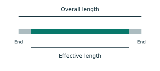
Sketch, not to scale; use the original dimensions.
- Find the effective length required by strength.
- Add the specified end allowance to each separate run.
- Round up, then check minimum size, spacing and returns.
Remember: Strength alone does not prove a weld detail is acceptable.
Thus the given detail has enough calculated strength but fails the course minimum fillet size.
A supported correction is leg with the same longitudinal runs, plus enlarged returns of at least ; choose returns as a design choice.
The corrected joint’s requested strength checks pass; cover tension is now the lowest resistance.
The image remains the original / detail so the change is auditable.
Mechanism detailsFrom fillet leg to effective throat
The complete mechanism is explained below.
Read each stage together with its stated conditions; playback and interaction are not required.
- An equal-leg fillet between perpendicular plates has an approximately right-triangular section.
For this geometry, throat .
It is shorter than the leg.
Effective resisting area = .
With here, capacity per length is .
- Use the course end allowances, minimum size and length rules; increasing the geometric length alone does not resolve every detailing check.
Lecturer's answer
| Item | Lecturer's value |
|---|---|
| 6 mm fillet weld strength | |
| Total weld length needed | |
| Weld per side (four sides) | → 220 mm, 15 mm returns |
| Main plate tension | |
| Two cover plates in tension |
Conclusion: Use 6 mm fillet welds, 220 mm on each side with 15 mm returns; the main and cover plates are adequate.
Source: Lecturer's tutorial solution, Ch 2, p. 3.
Result and concise exam wording
Use the same mechanism: Test every possible fracture cut. At fixed plate size, larger holes reduce the straight-path net area. A diagonal path needs its own stagger correction.
Use the same mechanism: The weld resists through its throat. At fixed weld strength, doubling the leg doubles throat and line resistance in this model. Detailing limits can prevent that choice.
Use the same mechanism: A table value has conditions. A different flange thickness can select a lower design strength even when the steel grade name remains unchanged.
Apply the reasoning to this section’s data and conditions
Given weld: four effective runs per half, capacity 873.6 kN>850.
Main/cover pair tension / pass.
However thicker part requires minimum fillet.
Therefore, the drawn detail fails that condition.
Proposed correction: fillet, runs, returns; weld capacity , acceptable size range and plate capacities unchanged.
Misconceptions and checks
Use the same mechanism: The weld resists through its throat. At fixed weld strength, doubling the leg doubles throat and line resistance in this model. Detailing limits can prevent that choice.
Apply the reasoning to this section’s data and conditions
- Deduct on each run.
- Do not count corner returns as extra needed resistance without a consistent model.
- Check minimum size even when strength passes.
- After increasing weld size, update effective lengths and returns.
How the method transfers to a new variant
Add force components at each bolt
An in-plane load acts away from the bolt-group centre. Find the largest resultant bolt force.
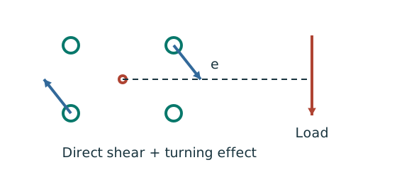
Prediction, then explanation. At fixed force, increasing eccentricity increases the moment component. Its direction differs between bolts.
Locate the bolt-group centre and coordinates. Add horizontal components together and vertical components together before finding each resultant.
e, xi and yi use mm; J uses mm². With M in kN·mm, each moment-force component is in kN.
Scope. These expressions use the stated elastic, equal-bolt in-plane model. Out-of-plane tension and prying require another model.
Check and takeaway. Do not add force magnitudes before resolving directions. Two perpendicular forces of 3 and 4 kN give 5 kN, not 7 kN.
An eccentric bracket pulls bolts differently
An out-of-plane moment rotates the bracket about the stated pivot. Determine the bolt tension pattern.
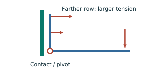
Prediction, then explanation. For unchanged geometry, doubling the applied moment doubles the modelled bolt tensions. Changing the pivot changes the distribution.
Use compatibility to relate tension to distance. Moment equilibrium then determines the proportionality factor.
M is moment in kN·mm. yi is distance from the stated pivot in mm. Ft,i is tension in kN.
Scope. Apply only to the stated active bolt set and pivot model. Flexible plates can create prying; use the supplied assumptions and resistance definitions.
Check and takeaway. A bolt’s lever arm is measured from the pivot used in the equation. It is not automatically its distance from the group centroid.
Use the same mechanism: The weld resists through its throat. At fixed weld strength, doubling the leg doubles throat and line resistance in this model. Detailing limits can prevent that choice.
Apply the reasoning to this section’s data and conditions
- Identify the force path and whether the joint is concentric, in-plane eccentric or out-of-plane eccentric.
Read all dimensions from the relevant view.
Do not measure drawing scale.
- Distinguish characteristic from ultimate loads and factor only when needed.
- Calculate demand per fastener/weld with the appropriate equilibrium model.
- Check all requested resistances and detailing conditions separately.
- State whether the given detail passes, fails, or remains conditional on missing data.
Prediction with explained answer
Use the same mechanism: The weld resists through its throat. At fixed weld strength, doubling the leg doubles throat and line resistance in this model. Detailing limits can prevent that choice.
Apply the reasoning to this section’s data and conditions
Prediction and explained answer.
Invented variant: keep the corrected weld but shorten each physical run to .
Does weld strength pass ?
Answer and reasoning
Effective length: Resistance: Fails.
Required actual length: Adopt or greater, then recheck all detailing requirements.
Mechanism detailsFrom fillet leg to effective throat
The complete mechanism is explained below.
Read each stage together with its stated conditions; playback and interaction are not required.
- An equal-leg fillet between perpendicular plates has an approximately right-triangular section.
For this geometry, throat .
It is shorter than the leg.
Effective resisting area = .
With here, capacity per length is .
- Use the course end allowances, minimum size and length rules; increasing the geometric length alone does not resolve every detailing check.