Mock Q2: full solution and invented marking guide
All marking guidance is invented.
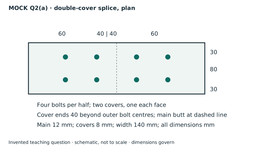
Invented mock-question diagram: double-cover splice in plan.
Four bolts per half, with one cover plate on each main-plate face.
The dashed line is the main-plate butt joint.
Each nearest bolt centre is from the joint.
Longitudinal pitch .
The cover plate projects beyond the outermost bolt centre.
Transverse dimensions , , .
Main-plate thickness ; cover-plate thickness ; width .
All diagram dimensions are in .
Not to scale; dimension labels govern.Open full-size image.
(a) Follow one splice half and every requested failure mode
Count cuts through each loaded bolt
Find how many shear planes transfer the force through one side of the connection.
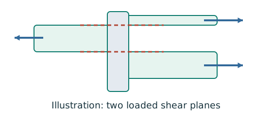
Prediction, then explanation. For equal sharing and unchanged bolt area, two active planes provide twice one plane’s shear resistance.
Select the area at the actual shear plane. Multiply by bolt shear strength. Count only the bolts and planes in the same transfer stage.
ps is bolt shear strength in N/mm²; As is the appropriate area in mm². nb counts bolts; ns counts equally loaded shear planes.
Scope. Use the thread area when threads cross the plane as required. Check bearing, plate failure and detailing separately.
Check and takeaway. Both halves of a butt splice carry the full transmitted force in sequence. Counting both halves together would double the apparent resistance.
Follow contact pressure into the plate
The bolt may survive shear while the connected plate deforms or tears near the hole.
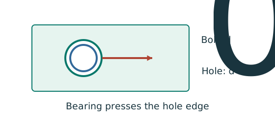
Prediction, then explanation. At fixed geometry and strength, a thicker plate raises plate resistance. Moving a hole too near the end can still govern.
Calculate every bound required by the supplied rule. The smallest applicable bound limits the connection at that layer.
pbs is the applicable bearing strength in N/mm²; d is nominal bolt diameter in mm; t is plate thickness in mm.
Scope. This diameter term alone is not the complete check. End-distance and clear-ligament limits, bolt bearing and each connected layer also matter.
Check and takeaway. Two covers and one main plate do not necessarily have the same thickness or strength. Compare the actual force share in each layer.
Test every possible fracture cut
Find the remaining steel area across a candidate tension-failure path.
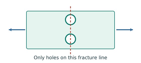
Prediction, then explanation. At fixed plate size, larger holes reduce the straight-path net area. A diagonal path needs its own stagger correction.
Subtract the hole widths crossed by the path, then multiply by thickness. Compare all plausible paths using the applicable course rule.
An is net area in mm²; b is plate width; d₀ is hole diameter; t is thickness, all in mm. n counts holes on this straight path.
Scope. This expression is for a straight cut. Effective area can require further shear-lag rules. Gross, net and effective areas must remain distinct.
Check and takeaway. Use the hole diameter, not the bolt diameter, when removing missing steel. The plate contains a hole, not solid steel around the bolt shank.
Apply the reasoning to this section’s data and conditions
Physical interpretation: Count where the bolt can be sheared
The plate interfaces are the places trying to cut across the bolt.
Sketch, not to scale; use the original dimensions.
- Count actual loaded shear planes, not merely visible plates.
- Choose shank or threaded area for the plane concerned.
- Compare group resistance with the force that group transfers.
Remember: Bolts on opposite sides of a splice do not all act in parallel.
Physical interpretation: Why holes reduce tension resistance
The pull must squeeze through the steel left beside the holes.
Sketch, not to scale; use the original dimensions.
- Choose a possible fracture line across the member.
- Subtract the holes crossed by that line using hole diameter.
- Apply the course effective-area rule and its gross-area limit.
Remember: Do not subtract every hole anywhere in the connection.
Each transfer half carries the full .
Four bolts share it: per bolt.
Each cover/plane takes .
Eight bolts exist overall, but halves transfer load in series.
Do not divide by .
Connected-part bearing uses the least of all applicable terms.
Main and cover end distances are ; clear hole ligament .
Main web/plate load per bolt ; cover load per bolt .
A critical transverse tension section crosses TWO holes, one in each bolt line.
Longitudinally separated holes are not all deducted at the same cut.
Longitudinal pitch ; transverse spacing .
Governing maximum spacing ; / both pass.
Maximum cover-plate edge distance ; passes. The thicker main plate permits a larger maximum edge distance.
Width check: .
All requested checks pass.
Main net tension is the lowest calculated full-half resistance.
This scoped result does not claim an unrequested complete block-shear design.
Mechanism detailsCount the bolt shear planes
The complete mechanism is explained below.
Read each stage together with its stated conditions; playback and interaction are not required.
- Load must cross an interface between the connected plates.
- A lap joint gives one shear plane through a bolt.
A symmetric double-cover joint may provide two shear planes.
Count load-transfer interfaces, not just visible plates.
Use the source’s area and shear strength.
Then check bearing, plate resistance and detailing separately.
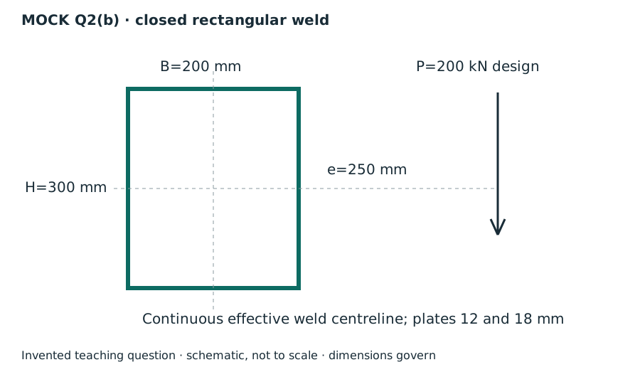
Invented mock-question diagram: closed rectangular weld.
is width.
is height; dashed lines intersect at the centroid.
The downward design force acts at eccentricity from the centroid.
Green lines are the continuous effective weld centrelines.
Plate thickness and .
Not to scale; stated dimensions govern.Open full-size image.
(b) Direct shear plus torsion at the reinforcing corner
Treat a weld group as lines
An eccentric force creates direct line force and torsional line force in the same weld group.
Prediction, then explanation. Increasing eccentricity increases the torsional contribution. The governing corner depends on vector addition, not distance alone.
Find the line centroid. Integrate squared distance along the effective lines. Add direct and torsional components at every candidate critical point.
J is line polar inertia in mm³. x and y use mm. With M in kN·mm, q is line force in kN/mm.
Scope. A solid rectangle has area inertia in mm⁴ and is not this weld-line model. Missing weld sides change the centroid and integrals.
Check and takeaway. Compare the largest resultant line force with the selected throat resistance. Keep kN/mm distinct from total force in kN.
The weld resists through its throat
Convert a visible fillet leg into resistance per effective length.
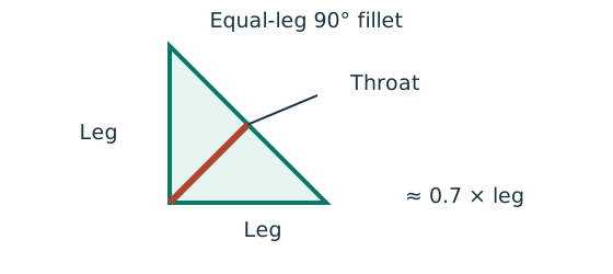
Prediction, then explanation. At fixed weld strength, doubling the leg doubles throat and line resistance in this model. Detailing limits can prevent that choice.
For the course right-angle equal-leg fillet, take throat as 0.7 times leg. Multiply throat area per unit length by weld strength.
s and a are leg and throat in mm. pw is weld strength in N/mm². qcap is resistance in kN/mm.
Scope. Use effective length, the correct steel/electrode strength and permitted leg limits. Full-penetration butt welds use a different model.
Check and takeaway. Illustration: a 6 mm leg at 250 N/mm² gives .
Apply the reasoning to this section’s data and conditions
Physical interpretation: Only the weld lines resist as weld
Imagine a wire rectangle: its empty middle is not more wire.
Sketch, not to scale; use the original dimensions.
- Count only the weld runs actually shown.
- Use their total length and line second moments.
- Combine direct and torsional forces at the critical location.
Remember: Line second moments have units ; plate-area moments use .
Physical interpretation: Add arrows before taking the magnitude
Walking east and walking north do not point in the same direction.
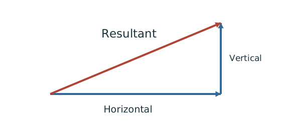
Sketch, not to scale; use the original dimensions.
- Choose signed horizontal and vertical directions.
- Add contributions along each direction separately.
- For perpendicular components, use the right-triangle resultant.
Remember: Check the corner where direct and torsional components reinforce each other.
Use the weld-length centroid at the rectangle centre.
Corner , .
Direct downward shear adds to torsional vertical shear on one side.
That side governs.
Weld-line inertias have units of .
The strength requirement alone would permit a small leg.
However, the thicker plate gives minimum .
At the thinner edge maximum=.
Choose : qcap 1.05 kN/mm, which exceeds the calculated demand.
This closed effective-line mock does not use two-end deductions on each rectangle side.
The geometry was expressly defined as continuous.
Mechanism detailsA weld group is a set of lines
The complete mechanism is explained below.
Read each stage together with its stated conditions; playback and interaction are not required.
- The centre is empty: resistance comes from the weld lines, not a solid plate filling the group.
Use line lengths for centroid weighting.
Line second moments have units .
Add the parallel-axis terms.
Direct force per length is .
The eccentric moment adds tangential flow proportional to distance from the centroid.
- Combine signed components at every candidate corner, then compare the maximum with throat resistance per length.
Compact script and invented marking guide
Use the same mechanism: Count cuts through each loaded bolt. For equal sharing and unchanged bolt area, two active planes provide twice one plane’s shear resistance.
Use the same mechanism: Follow contact pressure into the plate. At fixed geometry and strength, a thicker plate raises plate resistance. Moving a hole too near the end can still govern.
Use the same mechanism: Test every possible fracture cut. At fixed plate size, larger holes reduce the straight-path net area. A diagonal path needs its own stagger correction.
Apply the reasoning to this section’s data and conditions
(a) Four bolts/half, double shear:; bolt bearing ; main plate bearing ; main tension .
Each cover bearing and tension .
All exceed corresponding / actions; layout passes. (b) ; strength leg; detailing governs choose .
Invented credit: (a) force sharing , bolt checks , connected-part bearing , tension , layout/conclusion . (b) centroid/eccentric moment , length/inertias , corner components/resultant , size/detail/conclusion .
Mechanism detailsFollow the calculation sequence
The complete mechanism is explained below.
Read each stage together with its stated conditions; playback and interaction are not required.
- Locate the load, supports, connection geometry and any stated assumptions.
- Keep given values, table lookups and calculated values distinct; reconcile their units.
- The calculation player steps through the existing expressions in their original order.
Compare demand with resistance or the relevant limit.
Keep missing inputs and conditional conclusions explicit.