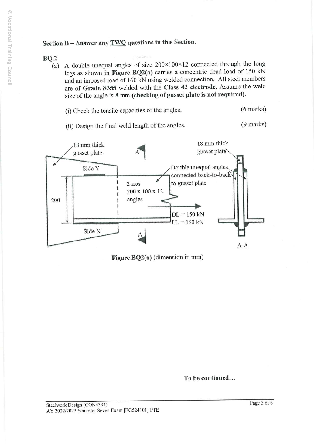
2023 BQ2(a): double welded unequal angles
Check tensile capacity and design final fillet-weld lengths for two S355 unequal angles connected through their long legs to an gusset. Characteristic tension: dead and imposed . S355/Class 42; the question excludes gusset-plate checking.
Original source: Pastpaper/22ENGTY033.pdf — p. 3.
A given value comes from the question or diagram.
A lookup value comes from the named table.
A calculated value follows from the working.
Each assumption is stated where the calculation needs it.
Known information, diagram labels and unknowns
One connected leg does not load both legs equally
An angle carries tension through only one leg. Determine how much section area the design rule permits.
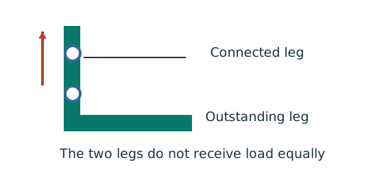
Prediction, then explanation. Keeping the same gross area does not guarantee the same tension resistance when the connection arrangement changes.
Separate connected and outstanding leg areas. Include the actual holes. Then use the supplied single-angle or double-angle effective-area rule.
Ae is the effective area from the applicable angle rule in mm². py is the relevant design strength in N/mm².
Scope. Do not assume the whole gross area is effective. Symmetry, connected leg and connection type determine which rule applies.
Check and takeaway. The outstanding leg contributes through load transfer; the rule need not either count all of it or discard all of it.
The weld resists through its throat
Convert a visible fillet leg into resistance per effective length.
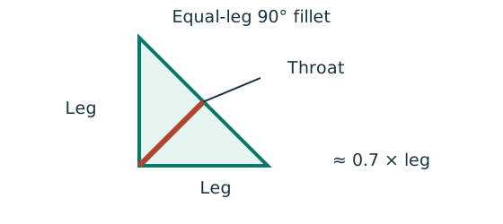
Prediction, then explanation. At fixed weld strength, doubling the leg doubles throat and line resistance in this model. Detailing limits can prevent that choice.
For the course right-angle equal-leg fillet, take throat as 0.7 times leg. Multiply throat area per unit length by weld strength.
s and a are leg and throat in mm. pw is weld strength in N/mm². qcap is resistance in kN/mm.
Scope. Use effective length, the correct steel/electrode strength and permitted leg limits. Full-penetration butt welds use a different model.
Check and takeaway. Illustration: a 6 mm leg at 250 N/mm² gives .
A table value has conditions
Find a design property without mixing a row, column or standard from a different case.
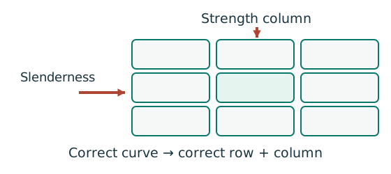
Prediction, then explanation. A different flange thickness can select a lower design strength even when the steel grade name remains unchanged.
Match the complete section designation. Read the relevant axis and unit. For strength tables, select material, thickness and curve before interpolating.
Given values come from the question. Lookup values come from a named table. Assumed values require an explicit condition.
Scope. A missing row or omitted restraint cannot be recovered from a schematic’s scale. Keep the result conditional when required data are absent.
Check and takeaway. Record the table, row, column and unit beside the substitution. That makes a later check possible.
Apply the reasoning to this section’s data and conditions
| Input | Origin |
|---|---|
| Materials/sizes | Given two angles, gusset, fillet, S355/Class 42. |
| Centroid lookup | Data File p.12, row, : , measured from the heel along the long leg. is the other coordinate. |
| Angle area method | Course rectangular leg split: share the corner thickness equally. Do not silently mix this area with table root-fillet area . |
| Weld detail choices | No longitudinal lengths are given. The final dimensions below are design selections, not measurements from the sketch. |
Why this method applies
Unequal lever arms require unequal forces
Two longitudinal welds must transfer a tensile force through the angle centroid without an unintended moment.
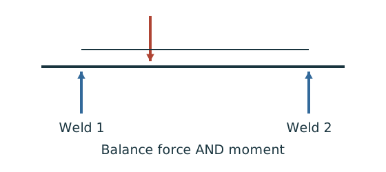
Prediction, then explanation. The weld with the shorter lever arm must carry more force to balance the longer-arm weld’s moment.
Use force balance and moment balance together. Then divide each force by its own line resistance to find required effective length.
P, F₁ and F₂ are forces. z₁ and z₂ are perpendicular distances from the load line. Use consistent length units.
Scope. Equal force shares apply only to the symmetric case. Physical terminated weld length also needs the supplied end deductions.
Check and takeaway. If the two lever arms become equal, the equations return equal forces. That limiting case checks the force distribution.
Use the same mechanism: The weld resists through its throat. At fixed weld strength, doubling the leg doubles throat and line resistance in this model. Detailing limits can prevent that choice.
Apply the reasoning to this section’s data and conditions
Check the angles first, then split the pair force equally and balance each angle’s two weld forces about its centroid.
Force divided by weld strength gives effective length, not final physical length.
Finally apply all supplied length/leg rules.
A strength-only length can be too short for detailing.
(i) Tensile capacity of the double angles —6 printed marks
Use the same mechanism: One connected leg does not load both legs equally. Keeping the same gross area does not guarantee the same tension resistance when the connection arrangement changes.
Keep load categories separate
A floor carries permanent material and changing occupancy loads. Find the design load for the stated check.
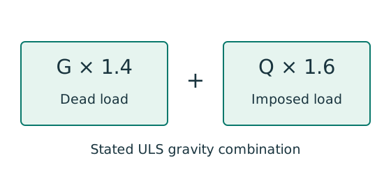
Prediction, then explanation. Increasing imposed load changes its own term. It does not change the dead-load factor or the steel stiffness.
First convert mass to weight where required. Next collect G and Q in compatible units. Apply the combination specified by the course problem.
G is characteristic dead load; Q is characteristic imposed load. Wu is the design load for this course gravity combination.
Scope. This combination is not universal. Use the specified service load for deflection and the stated factors for other standards or cases.
Check and takeaway. Illustration: G = 10 kN and Q = 5 kN give 22 kN. Factoring their sum by one guessed factor loses the distinction.
Apply the reasoning to this section’s data and conditions
Physical interpretation: One connected leg does not load both legs equally
The connected leg receives the pull first.
The other leg receives it through the angle.
Sketch, not to scale; use the original dimensions.
- Identify connected and outstanding legs from the drawing.
- Use the relevant bolted or welded angle rule.
- Keep the lecturer’s area convention consistent.
Remember: Bolted and welded reduction expressions are not the same rule.
A single welded angle would use rather than .
Gusset capacity is deliberately not checked because the question expressly excludes it.
Mechanism detailsWhy a connected angle leg matters
The complete mechanism is explained below.
Read each stage together with its stated conditions; playback and interaction are not required.
- Locate the connected leg, outstanding leg and centroid before using the table.
- Only the connected leg directly receives the fastener force.
The outstanding area may not become equally effective at the same section.
This motivates the effective-area rule.
Bolted, welded, single-angle and double-angle details can have different rules.
Preserve the formula attached to the original case.
(ii) Weld force balance, physical lengths and detailing —9 printed marks
Use the same mechanism: Unequal lever arms require unequal forces. The weld with the shorter lever arm must carry more force to balance the longer-arm weld’s moment.
Use the same mechanism: The weld resists through its throat. At fixed weld strength, doubling the leg doubles throat and line resistance in this model. Detailing limits can prevent that choice.
Apply the reasoning to this section’s data and conditions
Physical interpretation: Why two weld lengths can be unequal
Two side welds must balance the load about its actual line of action.
Sketch, not to scale; use the original dimensions.
- Find the load line and the lever arm to each weld.
- Balance moments as well as the total force.
- Convert each weld’s force into its own required length.
Remember: Equal-looking legs do not justify equal weld forces without equilibrium.
Physical interpretation: Drawn length and useful length differ
The start and end of a weld are not credited as fully effective in this course model.
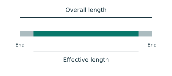
Sketch, not to scale; use the original dimensions.
- Find the effective length required by strength.
- Add the specified end allowance to each separate run.
- Round up, then check minimum size, spacing and returns.
Remember: Strength alone does not prove a weld detail is acceptable.
The connected leg is high.
The angle centroid is from SideX.
Therefore, the opposite lever arm to SideY is .
Use the opposite lever arm in each force share.
Those are the arithmetic strength minima.
However Ch 2 p.33 provision(6) says an end-connection weld length should not be less than the transverse spacing.
Here the separation is .
Therefore do not present / as a finished detail satisfying every supplied lecture rule.
One deliberately conservative final choice is SideX392 mm and SideY220 mm physical, on each angle.
Both exceed , and their effective lengths / nearly preserve the centroid-balancing ratio /.
These are chosen design dimensions.
The gusset outline must accommodate them.
To avoid relying on an approximate balance after rounding, verify the actual two-line group:
The bound adds magnitudes conservatively, so it is at least as severe as the actual vector resultant.
Final / runs with returns satisfy the stated leg, length and lap rules.
There are other valid overstrength choices.
No official expected final length is supplied.
The strength-only / calculation is shown so the exam method remains recognizable, while its detailing limitation is explicit.
Mechanism detailsBalance two weld forces
The complete mechanism is explained below.
Read each stage together with its stated conditions; playback and interaction are not required.
- The angle centroid/load line is generally not halfway between the two weld runs.
.
Both weld runs contribute to the applied force.
.
The run nearer the load line carries more force.
For equal throat resistance per length, the required effective lengths follow the same ratio.
Add detailing allowances afterwards.
Result and concise exam wording
Use the same mechanism: The weld resists through its throat. At fixed weld strength, doubling the leg doubles throat and line resistance in this model. Detailing limits can prevent that choice.
Apply the reasoning to this section’s data and conditions
.
The complete pair of angles .
Each angle , centroid lever arm /; , .
fillet weld , required effective length /, minimum actual length selected for strength /.
The lecture’s end-connection spacing rule requires a longer weld.
Here the fully checked selection exceeds : each angle /, return welds; conservative actual-group result .
The question excludes the gusset-plate check.
Misconceptions and checks
Use the same mechanism: The weld resists through its throat. At fixed weld strength, doubling the leg doubles throat and line resistance in this model. Detailing limits can prevent that choice.
Apply the reasoning to this section’s data and conditions
- Do not put on each angle.
- Do not use the centroid coordinate perpendicular to the connected long leg.
- Do not stop at effective lengths.
- Do not overlook the lecture’s length-versus-transverse-spacing rule.
How the method transfers to a new variant
Use the same mechanism: Unequal lever arms require unequal forces. The weld with the shorter lever arm must carry more force to balance the longer-arm weld’s moment.
Use the same mechanism: The weld resists through its throat. At fixed weld strength, doubling the leg doubles throat and line resistance in this model. Detailing limits can prevent that choice.
Apply the reasoning to this section’s data and conditions
- Check tension with the correct double-welded reduction.
- Balance side forces about the angle centroid.
- Calculate throat strength and effective lengths.
- Add end allowances and apply all stated detailing bounds.
- When rounding changes the group centroid, verify the actual provided geometry.
Prediction with explained answer
Use the same mechanism: Unequal lever arms require unequal forces. The weld with the shorter lever arm must carry more force to balance the longer-arm weld’s moment.
Use the same mechanism: The weld resists through its throat. At fixed weld strength, doubling the leg doubles throat and line resistance in this model. Detailing limits can prevent that choice.
Apply the reasoning to this section’s data and conditions
Prediction and explained answer.
Invented reasoning check: why are the strength-only SideX andSideY lengths unequal?
Answer and reasoning
The angle centroid is closer to SideX than SideY.
To place the resultant through that centroid, the nearer SideX carries while SideY carries .
Equal weld stress/size therefore requires unequal effective lengths.
It is not because the long leg carries the full pair’s load.