Tutorial 3 Q3: remove slab restraint and check B2/B3 LTB
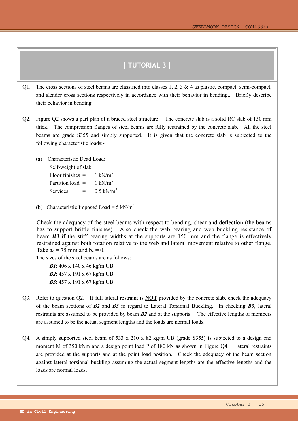
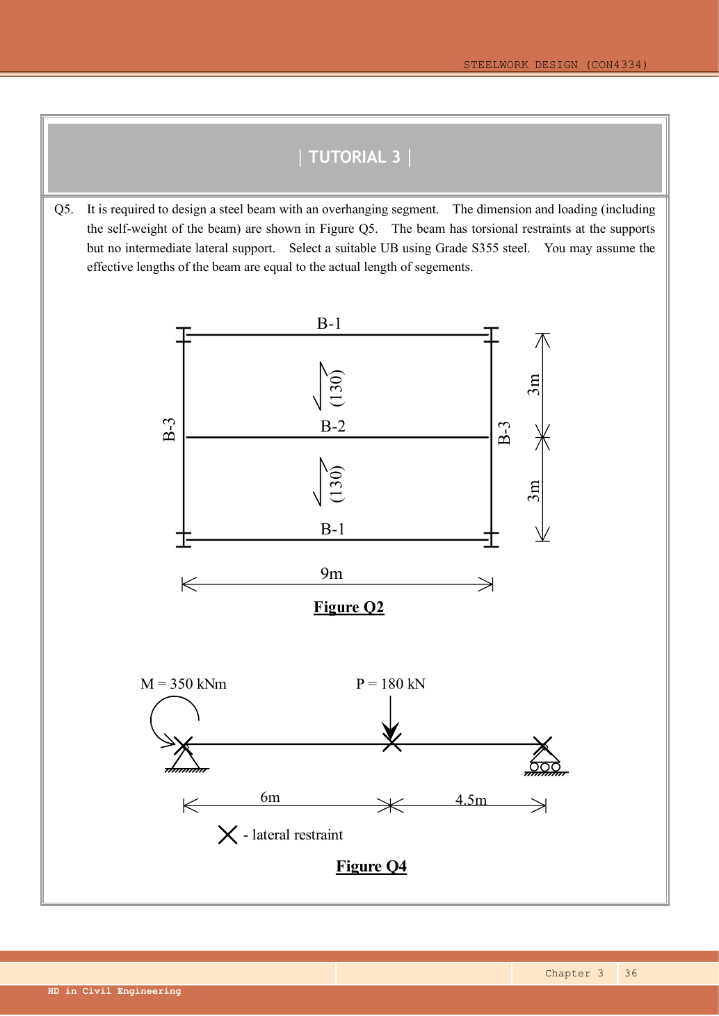
Repeat the Q2 B2 and B3 assessment for lateral-torsional buckling when the slab does not provide full lateral restraint. B3 has lateral restraints at the supports and at B2. Use actual segment lengths as effective lengths and normal loads.
Original source: LectureNotes/Ch 3_Beam.pdf — p. 35, p. 36.
A given value comes from the question or diagram.
A lookup value comes from the named table.
A calculated value follows from the working.
Each assumption is stated where the calculation needs it.
Known information, diagram labels and unknowns
A concentrated force spreads into the web
Check local web resistance at a support or concentrated load, even if overall beam strength passes.
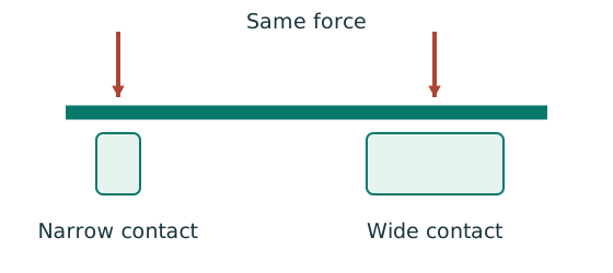
Prediction, then explanation. A longer valid stiff-bearing length can spread the same force over more web. A flexible contact is not automatically stiff bearing.
Match the actual bearing geometry to its source sketch. Use that sketch’s dimensions and permitted spread to calculate the resisting region.
b₁ is stiff-bearing length in mm. Web thickness and applicable design strength enter the prescribed local resistance equation.
Scope. End and interior cases can differ. A lateral-restraint symbol does not provide a bearing length or a load-introduction detail.
Check and takeaway. If bearing geometry is missing, give the applicable symbolic check and state the missing input. Do not borrow another example’s dimensions.
A safe beam can still sag too far
Check whether the beam displacement exceeds the permitted service limit.
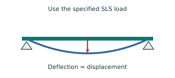
Prediction, then explanation. For the same UDL and stiffness, doubling span multiplies deflection by sixteen. Doubling I halves deflection.
Load bends each beam segment. The curvature accumulates along the span. Material stiffness E and geometric stiffness I resist that deformation.
Use w in N/mm, L in mm, E in N/mm² and I in mm⁴. The resulting midspan deflection is in mm.
Scope. The formula assumes a prismatic, simply supported, linear-elastic beam with full-span UDL. Use the stated service load and deflection limit.
Check and takeaway. A higher yield grade does not automatically increase E. Passing a strength check therefore does not prove acceptable deflection.
Follow one strip of floor
An area load must become a beam load before beam reactions can be calculated.
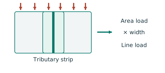
Prediction, then explanation. At fixed area load, twice the tributary width gives twice the line load. An end reaction remains a concentrated force.
Consider one metre along the beam. The associated floor area is b square metres. Multiply area load by that width.
q is area load in kN/m²; b is tributary width in m; w is line load in kN/m.
Scope. Determine b from slab spanning and supports. Add beam self-weight separately. A secondary-beam reaction is not automatically a UDL.
Check and takeaway. Illustration: . The width cancels one length unit.
Apply the reasoning to this section’s data and conditions
| Given or adopted input | Exact origin |
|---|---|
| Floor geometry | FigureQ2: each horizontal B1/B2 spans ; vertical B3 spans . Slab spans vertically between horizontal beams. |
| Tributary widths | Top/bottom B1 takes half of one slab bay=. Middle B2 takes from each side=. |
| Slab thickness | The parenthesised in each slab bay denotes RC slab. It is not a load intensity. |
| Surface loads | Q2 text: finishes , partitions , services , imposed , all . |
| Members | B1 UB; B2 and B3 UB; S355, simple supports and full compression-flange restraint for Q2. |
| Additional B3 support data | Stiff bearing , aₑ75 mm, bₑ0. Both local flange restraints explicitly given. |
| Table mass for self-weight | kg/m and from Data File p.9; multiply by the assumed for this numerical demonstration. |
Keep (concrete unit weight, ) and (acceleration, ) symbolic until supplied.
These equations are the source-supported general solution for the missing inputs:
Reuse the load path fully derived in Q2: B2 , .
B3 central , self-weight , reaction , midspan .
Removing restraints changes stability, not these simply supported vertical-load internal forces.
Why this method applies
Vertical bending can trigger sideways motion
A beam has enough local bending resistance. Check whether its compression flange can move sideways and twist.
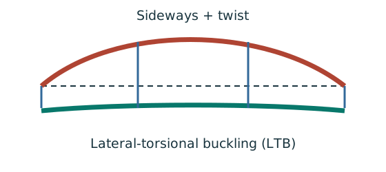
Prediction, then explanation. Adding a valid lateral restraint shortens a stability segment. It need not change the beam’s vertical reaction or moment diagram.
Identify the compressed flange and effective restraints. Calculate the specified slenderness, read buckling strength and compare resistance with the segment demand.
LE and ry use the same length unit. pb uses N/mm²; Sx uses mm³; Mb uses N·mm. mLT is dimensionless.
Scope. Use the specified section class, effective-length branch and loading condition. Load height alone does not prove a destabilizing case.
Check and takeaway. Removing a lateral restraint requires a new segment stability check. The old shorter-segment result cannot establish the longer segment’s adequacy.
Apply the reasoning to this section’s data and conditions
A section can pass its local bending resistance and still buckle sideways.
For each unrestrained length, calculate its own equivalent uniform moment and its own λᴸᵀ.
Do not use B3’s total where the midpoint is an effective restraint.
1. B2: the full is unrestrained
Use the same mechanism: Vertical bending can trigger sideways motion. Adding a valid lateral restraint shortens a stability segment. It need not change the beam’s vertical reaction or moment diagram.
Moment shape matters within one segment
Represent a nonuniform moment distribution in the applicable member-buckling equation.
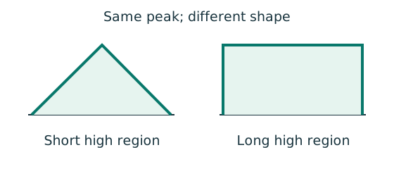
Prediction, then explanation. Two segments can have equal peak moment but different distributions. Their equivalent moment factors can therefore differ.
Evaluate moments from the true whole-beam analysis at the required positions. Apply the exact table’s weights, signs and lower bound.
mLT is an LTB factor. mx and my belong to the specified flexural checks. They are not interchangeable.
Scope. Some rules use magnitudes; others require signed ordinates. A factor does not reduce the actual moment used in a local section check.
Check and takeaway. Measure quarter points from the segment start, not automatically from the beam’s left support.
Move between two known values
The required slenderness lies between two table rows. Estimate the strength on the straight segment between those rows.
Prediction, then explanation. If the second strength is lower, moving toward that row must reduce the interpolated strength.
Subtract the lower input to find distance travelled. Divide by the input interval. Multiply that fraction by the output change.
x is the required input. The two known pairs are (x₀, y₀) and (x₁, y₁). f has no unit.
Scope. Use one table, curve and strength column. This interpolation does not permit extrapolation or inventing an intermediate steel section.
Check and takeaway. Illustration: between strengths 200 and 180, a fraction of 0.4 gives 192 N/mm². The result lies between both endpoints.
Apply the reasoning to this section’s data and conditions
Physical interpretation: How much does the beam sag?
Strength asks whether it fails; deflection asks how far it moves.
Sketch, not to scale; use the original dimensions.
- Use the serviceability load case specified by the course question.
- Choose the expression matching the support and load positions.
- Use consistent units for load, length, E and I.
Remember: The largest deflection is not always at midspan.
Lookup: Data File pp.9–10, exact UB row.
Dimensions on p.9; properties on p.10.
is overall depth.
is the clear web depth between root fillets, not the nominal designation.
| Property | Lookup value / conversion |
|---|---|
| Dimensions | D453.4, web t 8.5, flange T12.7, root r 10.2, clear d 407.6, all |
| Local ratios | ;。 |
| Major-axis properties | ; ; . |
| LTB properties | ; ; torsional index . |
For a simply supported full UDL the quarter-point moments are , and .
Table 8.4b therefore gives:
Normal-load effective length is the given segment length.
All quantities in and λᴸᵀ are dimensionless.
This Class 1 section has .
Table 8.3a, Data File p.5, pᵧ355 column:
B2 fails LTB severely.
Its Q2 fully restrained bending pass does not apply once the restraint is removed.
It needs an effective restraint arrangement or a larger verified section.
Mechanism detailsA beam bends sideways and twists
The complete mechanism is explained below.
Read each stage together with its stated conditions; playback and interaction are not required.
- For the illustrated sagging beam the top flange is compressed.
- The unrestrained compression flange can move sideways while the complete cross-section twists.
Only effective restraints divide the member into unbraced segments.
They do not automatically add vertical supports.
Use the segment effective length, section properties and matching moment factor.
This is an exaggerated mode shape, not a calculated displacement.
2. B3: check one segment and use symmetry
Use the same mechanism: Vertical bending can trigger sideways motion. Adding a valid lateral restraint shortens a stability segment. It need not change the beam’s vertical reaction or moment diagram.
Use the same mechanism: Moment shape matters within one segment. Two segments can have equal peak moment but different distributions. Their equivalent moment factors can therefore differ.
Use the same mechanism: Move between two known values. If the second strength is lower, moving toward that row must reduce the interpolated strength.
Apply the reasoning to this section’s data and conditions
Physical interpretation: How a floor load reaches a beam
Each beam collects the load from its own strip of floor.
Sketch, not to scale; use the original dimensions.
- Find the tributary width from the actual plan.
- Area load × tributary width gives load per beam length.
- A supporting beam receives the other beam’s end reaction.
Remember: A reaction becomes a point load, not automatically a UDL.
The two segments are mirror images.
On the left segment, is measured from the left support, before reaching the point load atx 3 m.
Therefore .
Use local quarter points , not quarters of the total .
Normal-load effective length is the given segment length.
All quantities in and λᴸᵀ are dimensionless.
This Class 1 section has .
Table 8.3a, Data File p.5, pᵧ355 column:
Both B3 segments pass.
The small self-weight makes its BMD slightly curved; using the actual ordinates avoids silently replacing it by a straight line.
The original shear, deflection and local support checks remain those in Q2.
Mechanism detailsA beam bends sideways and twists
The complete mechanism is explained below.
Read each stage together with its stated conditions; playback and interaction are not required.
- For the illustrated sagging beam the top flange is compressed.
- The unrestrained compression flange can move sideways while the complete cross-section twists.
Only effective restraints divide the member into unbraced segments.
They do not automatically add vertical supports.
Use the segment effective length, section properties and matching moment factor.
This is an exaggerated mode shape, not a calculated displacement.
Lecturer's answer
| Item | Lecturer's value |
|---|---|
| B2 (no intermediate restraint, 9 m) | , , , |
| B3 (midspan restraint, 3 m segments) | , , , |
Conclusion: B2 fails in lateral-torsional buckling (NOT O.K.); B3 passes.
Source: Lecturer's tutorial solution, Ch 3, pp. 7–8.
Result and concise exam wording
Balance the isolated beam
Find the two vertical reactions before calculating internal shear or moment.
Prediction, then explanation. Move the same load toward B. Reaction B increases because the load has a larger moment arm about A.
Take moments about A. Reaction A has zero lever arm there. Then use vertical force balance to find reaction A.
P, RA and RB are forces in kN. L is support spacing and a is load position, both in m.
Scope. These expressions describe one point load on a simply supported beam. Add other loads through equilibrium; keep their actual positions.
Check and takeaway. Illustration: P = 60 kN, L = 6 m and a = 2 m give RB = 20 kN and RA = 40 kN.
Apply the reasoning to this section’s data and conditions
B2: LE9,000 mm, mLT0.925, demand , Mb 105.451 kNm → fails.
B3: two LE3,000 mm segments, mLT0.602266, demand , Mb 373.479 kNm → both pass.
Normal loads and the explicitly assumed effective midpoint restraint are essential.
Misconceptions and checks
Use the same mechanism: Vertical bending can trigger sideways motion. Adding a valid lateral restraint shortens a stability segment. It need not change the beam’s vertical reaction or moment diagram.
Apply the reasoning to this section’s data and conditions
- Do not transfer B2’s effective length to B3.
- Do not claim concrete restraint in a question that removes it.
- Do not assume every supported beam inherently gives torsional restraint.
How the method transfers to a new variant
The loaded web can act as a short strut
A concentrated load can buckle the web instead of crushing it. This requires a separate local check.
Prediction, then explanation. Reduced local restraint can increase the relevant effective length and reduce local buckling resistance.
First calculate the source model’s effective strip and base resistance. Then apply the branch required by local restraint and load position.
Local web effective length is not the beam span or the LTB segment length. Use the symbol definition in the selected local formula.
Scope. The short-strut picture explains a mechanism; it is not a derivation of every coefficient in the supplied web rule.
Check and takeaway. A local bearing pass does not establish a local buckling pass. State both conclusions and any unresolved restraint condition.
Find which plate buckles first
Before using plastic bending resistance, check whether the flange and web can sustain the required stress distribution.
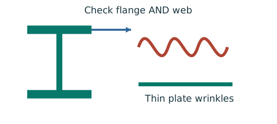
Prediction, then explanation. At fixed width, a thinner plate has a larger width-to-thickness ratio. Local buckling then becomes more restrictive.
Calculate the flange and web ratios separately. Compare each with the limits for its stress condition. The worse class governs.
py is the design yield strength in N/mm². ε is a dimensionless scale used in the supplied classification limits.
Scope. Pure bending and uniform compression use different web limits. Class 2 allows plastic resistance but not the Class 1 rotation capability.
Check and takeaway. A Class 1 web and Class 2 flange give a Class 2 section. Do not average the class numbers.
Use the same mechanism: A safe beam can still sag too far. For the same UDL and stiffness, doubling span multiplies deflection by sixteen. Doubling I halves deflection.
Apply the reasoning to this section’s data and conditions
- Read slab direction, tributary widths, beam spans and restraint positions from the source.
- Separate characteristic dead/imposed loads; factor only strength loads.
- Pass a supporting beam the reaction from the supported beam, not its full load.
- Draw the beam free body, solve reactions and obtain shear/moment ordinates.
- Read the exact section row, classify and check shear before selecting the bending formula.
- Check imposed-load deflection with consistent and .
- Where requested, check bearing/web buckling and each unrestrained segment independently.
Prediction with explained answer
Use the same mechanism: Vertical bending can trigger sideways motion. Adding a valid lateral restraint shortens a stability segment. It need not change the beam’s vertical reaction or moment diagram.
A cut reveals the internal actions
Find where the beam moment is largest. A large load arrow alone does not locate that point.
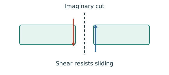
Prediction, then explanation. Under a uniform downward load, shear falls steadily. Moment reaches a stationary value where shear becomes zero.
Balance the forces on the cut piece to get V. Balance their moments about the cut to get M. Evaluate each load region separately.
x and L use m; w uses kN/m; V uses kN; M uses kN·m. These lines apply before any point load.
Scope. A point load adds a shear jump. A concentrated couple adds a moment jump. Check load points, supports and overhang roots too.
Check and takeaway. A UDL gives a sloping shear line and a curved moment line. A flat moment diagram therefore cannot represent a loaded UDL region.
Apply the reasoning to this section’s data and conditions
Prediction and explained answer.
Invented reasoning variant: B3’s midpoint connection ceases to provide lateral restraint.
What must be redone?
Answer and reasoning
Use one LTB segment, recompute its full-span quarter moments and , and recompute , , , and withLE6,000 mm.
The existing result no longer proves adequacy.
Vertical reactions, shear and bending from the same loads do not change.