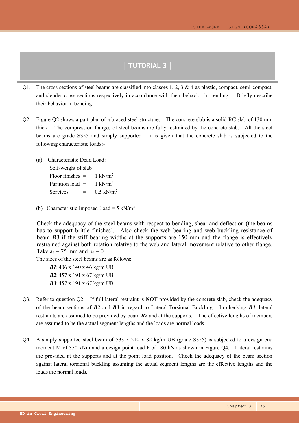
Tutorial 3 Q1: what the four section classes mean in bending
Describe the bending behaviour of Classes 1,2,3 and 4: plastic, compact, semi-compact and slender.
Original source: LectureNotes/Ch 3_Beam.pdf — p. 35.
A given value comes from the question or diagram.
A lookup value comes from the named table.
A calculated value follows from the working.
Each assumption is stated where the calculation needs it.
Known information, diagram labels and unknowns
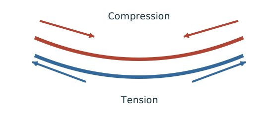
Internal tension and compression resist moment
Find which section resistance applies before comparing it with the moment demand.
Prediction, then explanation. A larger appropriate section modulus raises resistance at fixed strength. Local plate buckling can restrict the usable modulus.
Classify the section first. At low shear, use the elastic expression for Class 3 or the prescribed capped plastic expression for Classes 1 and 2.
py uses N/mm². S is plastic modulus and Z is elastic modulus, both in mm³. Mc then uses N·mm.
Scope. This is section resistance, not whole-member LTB resistance. High shear and Class 4 require their appropriate treatment.
Check and takeaway. Selecting the larger of the two capped terms defeats the cap. Use their minimum.
Apply the reasoning to this section’s data and conditions
Given: a bending section is assigned one of four local-buckling classes.
Required: describe moment resistance and rotation capacity.
No force, length, numerical section or steel grade is given.
Why this method applies
Separate stiffness, strength and ductility
Two steels may resist similar elastic deformation but start permanent deformation at different stresses.
Prediction, then explanation. Raising the yield level alone need not change the initial slope. The same elastic load can therefore give similar deformation.
Stress is force per area. Strain is extension divided by original length. Their elastic ratio defines Young’s modulus.
σ is stress in N/mm²; ε is dimensionless strain; E is Young’s modulus in N/mm².
Scope. Use this linear relationship only in its elastic range. Ductility concerns deformation before fracture, not the value of E.
Check and takeaway. When elastic load is removed, elastic strain recovers. Yielded steel can retain strain after unloading.
Apply the reasoning to this section’s data and conditions
Think about the order of three events: the first fibre yields, plastic stress spreads through the section, and a thin plate locally buckles.
Rotation capacity matters when a plastic hinge must keep turning while still carrying moment.
The four behaviours and their exam consequences
Find which plate buckles first
Before using plastic bending resistance, check whether the flange and web can sustain the required stress distribution.
Prediction, then explanation. At fixed width, a thinner plate has a larger width-to-thickness ratio. Local buckling then becomes more restrictive.
Calculate the flange and web ratios separately. Compare each with the limits for its stress condition. The worse class governs.
py is the design yield strength in N/mm². ε is a dimensionless scale used in the supplied classification limits.
Scope. Pure bending and uniform compression use different web limits. Class 2 allows plastic resistance but not the Class 1 rotation capability.
Check and takeaway. A Class 1 web and Class 2 flange give a Class 2 section. Do not average the class numbers.
Use the same mechanism: Internal tension and compression resist moment. A larger appropriate section modulus raises resistance at fixed strength. Local plate buckling can restrict the usable modulus.
Use the property for the physical question
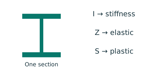
A section table contains several numbers. Choose the property that matches the calculation and bending axis.
Prediction, then explanation. Moving equal area away from an axis increases I about that axis. It does not increase total area.
Each small area contributes its area multiplied by squared distance. Sum those contributions to obtain I.
I is second moment of area in mm⁴. y is distance from the chosen axis in mm. A is area in mm². r is radius of gyration in mm.
Scope. Z is elastic section modulus; S is plastic section modulus in this course. Neither is interchangeable with I.
Check and takeaway. A nominal section designation is a row identifier. Use the actual dimensions and units in that exact row.
Apply the reasoning to this section’s data and conditions
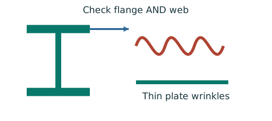
Physical interpretation: A thin part can wrinkle first
A thin plate may wrinkle before the whole steel member reaches its intended resistance.
Sketch, not to scale; use the original dimensions.
- Check flange and web slenderness using their own definitions.
- Compare each ratio with the correct class limits.
- The element with the more restrictive class determines the section class.
Remember: Bending limits and uniform-compression limits are different.
| Class | Behaviour before local buckling | Permitted course bending approach |
|---|---|---|
| 1 — plastic | Develops full plastic resistance and enough plastic rotation for a plastic hinge to redistribute moment. | Plastic resistance, with the course 1.2pᵧZ ceiling; suitable rotation capacity must still be relevant to the analysis. |
| 2 — compact | Develops plastic resistance, but local buckling limits the rotation available afterward. | Same capped plastic section resistance in the elastic-analysis examples. Do not claim adequate plastic-hinge rotation. |
| 3 — semi-compact | Extreme compression fibre can reach yield, but local buckling prevents full plastic stress redistribution. | Use elastic resistance pᵧZ for low-shear bending. |
| 4 — slender | Local plate buckling occurs before gross-section elastic yield resistance is reached. | Use effective section properties/local-buckling treatment. Neither gross pᵧS nor gross pᵧZ is automatically valid. |
The most slender relevant compression element governs the whole section class.
A stocky flange does not rescue a slender web.
Classification concerns local plates.
An otherwise Class 1 beam can still fail global lateral-torsional buckling.
Here pᵧ is design strength in , elastic modulus and plastic modulus in ; multiplication gives .
Divide by for .
The two modulus symbols are deliberately different.
Mechanism detailsWhy thin elements buckle locally
The complete mechanism is explained below.
Read each stage together with its stated conditions; playback and interaction are not required.
- The flange outstand and web have different widths, thicknesses and edge support conditions.
- A thinner plate can wrinkle locally before the complete member loses stability.
Class 1 allows plastic rotation.
Class 2 reaches plastic resistance.
Class 3 reaches elastic resistance.
Class 4 requires effective properties.
Check every relevant compression element with the supplied limits and stress distribution.
The deformation shown is qualitative.
Result and concise exam wording
Use the same mechanism: Separate stiffness, strength and ductility. Raising the yield level alone need not change the initial slope. The same elastic load can therefore give similar deformation.
Apply the reasoning to this section’s data and conditions
Class 1 reaches plastic resistance and permits adequate plastic rotation.
Class 2 reaches plastic resistance but has limited rotation.
Class 3 reaches elastic first-yield resistance, but cannot develop full plastic resistance.
Class 4 buckles locally before gross elastic resistance.
Use effective properties for Class 4.
Misconceptions and checks
Use the same mechanism: Find which plate buckles first. At fixed width, a thinner plate has a larger width-to-thickness ratio. Local buckling then becomes more restrictive.
Vertical bending can trigger sideways motion
A beam has enough local bending resistance. Check whether its compression flange can move sideways and twist.
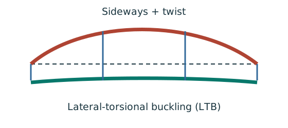
Prediction, then explanation. Adding a valid lateral restraint shortens a stability segment. It need not change the beam’s vertical reaction or moment diagram.
Identify the compressed flange and effective restraints. Calculate the specified slenderness, read buckling strength and compare resistance with the segment demand.
LE and ry use the same length unit. pb uses N/mm²; Sx uses mm³; Mb uses N·mm. mLT is dimensionless.
Scope. Use the specified section class, effective-length branch and loading condition. Load height alone does not prove a destabilizing case.
Check and takeaway. Removing a lateral restraint requires a new segment stability check. The old shorter-segment result cannot establish the longer segment’s adequacy.
Apply the reasoning to this section’s data and conditions
- Do not describe Class 2 as elastic-only.
- Do not equate section class with lateral restraint.
- Do not say Class 4 has zero strength.
How the method transfers to a new variant
A table value has conditions
Find a design property without mixing a row, column or standard from a different case.
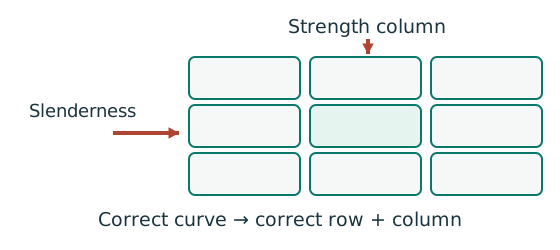
Prediction, then explanation. A different flange thickness can select a lower design strength even when the steel grade name remains unchanged.
Match the complete section designation. Read the relevant axis and unit. For strength tables, select material, thickness and curve before interpolating.
Given values come from the question. Lookup values come from a named table. Assumed values require an explicit condition.
Scope. A missing row or omitted restraint cannot be recovered from a schematic’s scale. Keep the result conditional when required data are absent.
Check and takeaway. Record the table, row, column and unit beside the substitution. That makes a later check possible.
Apply the reasoning to this section’s data and conditions
- Identify the compression plate elements.
- Compare relevant width/thickness ratios with the correct stress-pattern limits.
- Take the governing class.
- State its moment and rotation consequences separately.
Prediction with explained answer
Use the same mechanism: Vertical bending can trigger sideways motion. Adding a valid lateral restraint shortens a stability segment. It need not change the beam’s vertical reaction or moment diagram.
Apply the reasoning to this section’s data and conditions
Prediction and explained answer.
Invented variant: a beam is Class 1 but its compression flange is unrestrained over .
Can you omit LTB?
Answer and reasoning
No. Class 1 prevents premature local plate buckling for the assumed stress pattern.
It does not prevent the whole beam twisting and moving sideways.
LTB is a separate member check.