Graduated practice and unfamiliar variants
All questions on this page are invented practice, not extra past papers or predictions.
Work on paper.
First identify the mechanism, then select the formula.
A correct number with an unexplained wrong method does not count as independent mastery.
Stage 1: essential arithmetic and recognition
Change the ruler, keep the quantity
A section table uses centimetres, but the strength calculation uses millimetres. The numbers must describe the same section.
Prediction, then explanation. Would every property increase by ten? No. The exponent determines how many factors of ten are needed.
First identify the physical quantity. Next convert each length factor. Keep force and length conversions separate when converting a moment.
Here n is the length exponent: 2 for area, 3 for section modulus and 4 for second moment of area.
Scope. Changing units changes neither the load nor the section. A conversion factor cannot repair a formula for the wrong physical quantity.
Check and takeaway. Illustration: . The fourth power belongs to the unit, not the number 2.
Follow one strip of floor
An area load must become a beam load before beam reactions can be calculated.
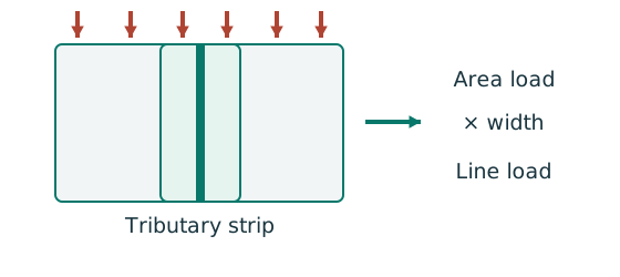
Prediction, then explanation. At fixed area load, twice the tributary width gives twice the line load. An end reaction remains a concentrated force.
Consider one metre along the beam. The associated floor area is b square metres. Multiply area load by that width.
q is area load in kN/m²; b is tributary width in m; w is line load in kN/m.
Scope. Determine b from slab spanning and supports. Add beam self-weight separately. A secondary-beam reaction is not automatically a UDL.
Check and takeaway. Illustration: . The width cancels one length unit.
Keep load categories separate
A floor carries permanent material and changing occupancy loads. Find the design load for the stated check.
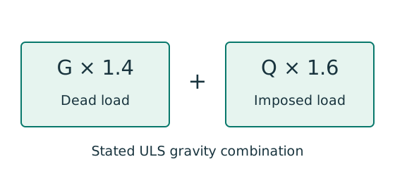
Prediction, then explanation. Increasing imposed load changes its own term. It does not change the dead-load factor or the steel stiffness.
First convert mass to weight where required. Next collect G and Q in compatible units. Apply the combination specified by the course problem.
G is characteristic dead load; Q is characteristic imposed load. Wu is the design load for this course gravity combination.
Scope. This combination is not universal. Use the specified service load for deflection and the stated factors for other standards or cases.
Check and takeaway. Illustration: G = 10 kN and Q = 5 kN give 22 kN. Factoring their sum by one guessed factor loses the distinction.
Apply the reasoning to this section’s data and conditions
P1 · units
Prediction and explained answer.
A section has , and .
Convert each to units.
Hint
Powers of length scale by the corresponding power of .
Answer and reasoning
; ; .
Do not apply the same factor to all three.
Mechanism detailsUnits and powers
The complete mechanism is explained below.
Read each stage together with its stated conditions; playback and interaction are not required.
- Force, length and stress must use compatible units before substitution.
.
An area has two length factors, so .
A section modulus has ; second moment of area has .
Use and for cm to mm.
.
Divide by to express that moment in .
P2 · area to line load
Prediction and explained answer.
A slab has , and beam tributary width .
Beam self-weight is .
Find design line load.
Hint
Keep and separate; self-weight is dead load.
Answer and reasoning
;。
Mechanism detailsFollow the floor load in 3D
The complete mechanism is explained below.
Read each stage together with its stated conditions; playback and interaction are not required.
The floor carries pressure in .
The highlighted strip belongs to one secondary beam.
Multiply pressure by tributary width: .
The illustration uses .
- A primary beam receives the secondary beam reaction at their connection, not a new full-span UDL.
Trace reactions down to columns and foundations.
Count each loaded area once.
P3 · reaction and moment
Prediction and explained answer.
The P2 beam is simply supported over .
Find reactions and peak bending moment.
Hint
Symmetry gives equal reactions.
The shear changes sign at midspan.
Answer and reasoning
Total=; .
Check and .
Mechanism detailsBalance reactions and moments
The complete mechanism is explained below.
Read each stage together with its stated conditions; playback and interaction are not required.
This demonstrator is a simply supported 6 m beam with a 60 kN point load.
It is not the page’s original loading diagram.
.
Moving the load towards B increases .
.
The two upward reactions must sum to P.
With the load at midspan, .
End couples, UDLs and overhangs require their own equilibrium terms.
P4 · method selection
Prediction and explained answer.
A vertical support is present at each end of an beam and a lateral restraint at .
How many vertical spans and LTB segments exist?
Hint
Separate sideways restraint from vertical support.
Answer and reasoning
One vertical span; two LTB segments, and .
Analyze vertical moments over the beam first.
Moment at the lateral restraint is not necessarily zero.
P5 · strength row
Prediction and explained answer.
S355 flange thickness is , and web under bending.
Classify the section.
Hint
Use py 345, then compare flange with and and web with .
Answer and reasoning
.
Flange , but , Class 2.
Web , Class 1.
Overall Class 2; capped plastic moment resistance is permitted at low shear.
Mechanism detailsWhy thin elements buckle locally
The complete mechanism is explained below.
Read each stage together with its stated conditions; playback and interaction are not required.
- The flange outstand and web have different widths, thicknesses and edge support conditions.
- A thinner plate can wrinkle locally before the complete member loses stability.
Class 1 allows plastic rotation.
Class 2 reaches plastic resistance.
Class 3 reaches elastic resistance.
Class 4 requires effective properties.
Check every relevant compression element with the supplied limits and stress distribution.
The deformation shown is qualitative.
Mechanism detailsUnits and powers
The complete mechanism is explained below.
Read each stage together with its stated conditions; playback and interaction are not required.
- Force, length and stress must use compatible units before substitution.
.
An area has two length factors, so .
A section modulus has ; second moment of area has .
Use and for cm to mm.
.
Divide by to express that moment in .
Stage 2: choose and apply a resistance
Count cuts through each loaded bolt
Find how many shear planes transfer the force through one side of the connection.
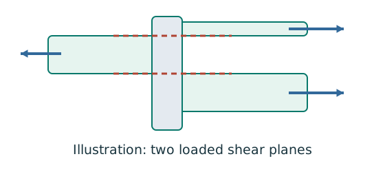
Prediction, then explanation. For equal sharing and unchanged bolt area, two active planes provide twice one plane’s shear resistance.
Select the area at the actual shear plane. Multiply by bolt shear strength. Count only the bolts and planes in the same transfer stage.
ps is bolt shear strength in N/mm²; As is the appropriate area in mm². nb counts bolts; ns counts equally loaded shear planes.
Scope. Use the thread area when threads cross the plane as required. Check bearing, plate failure and detailing separately.
Check and takeaway. Both halves of a butt splice carry the full transmitted force in sequence. Counting both halves together would double the apparent resistance.
Follow contact pressure into the plate
The bolt may survive shear while the connected plate deforms or tears near the hole.
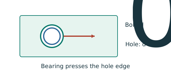
Prediction, then explanation. At fixed geometry and strength, a thicker plate raises plate resistance. Moving a hole too near the end can still govern.
Calculate every bound required by the supplied rule. The smallest applicable bound limits the connection at that layer.
pbs is the applicable bearing strength in N/mm²; d is nominal bolt diameter in mm; t is plate thickness in mm.
Scope. This diameter term alone is not the complete check. End-distance and clear-ligament limits, bolt bearing and each connected layer also matter.
Check and takeaway. Two covers and one main plate do not necessarily have the same thickness or strength. Compare the actual force share in each layer.
An eccentric bracket pulls bolts differently
An out-of-plane moment rotates the bracket about the stated pivot. Determine the bolt tension pattern.
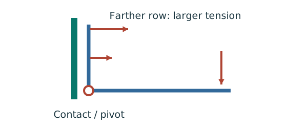
Prediction, then explanation. For unchanged geometry, doubling the applied moment doubles the modelled bolt tensions. Changing the pivot changes the distribution.
Use compatibility to relate tension to distance. Moment equilibrium then determines the proportionality factor.
M is moment in kN·mm. yi is distance from the stated pivot in mm. Ft,i is tension in kN.
Scope. Apply only to the stated active bolt set and pivot model. Flexible plates can create prying; use the supplied assumptions and resistance definitions.
Check and takeaway. A bolt’s lever arm is measured from the pivot used in the equation. It is not automatically its distance from the group centroid.
Apply the reasoning to this section’s data and conditions
P6 · threaded double shear
Prediction and explained answer.
FourM20 Grade 8.8 bolts carry through a symmetric double-cover splice.
Threads cross both shear planes.
Is bolt shear adequate?
Hint
Per bolt there are two planes.
The full joint force is divided among four bolts on ONE transfer half.
Answer and reasoning
, .
One plane ; two planes ; four bolts .
Demand per bolt ; per symmetric shear plane .
This checks bolt shear only; plates and layout require separate checks.
Mechanism detailsCount the bolt shear planes
The complete mechanism is explained below.
Read each stage together with its stated conditions; playback and interaction are not required.
- Load must cross an interface between the connected plates.
- A lap joint gives one shear plane through a bolt.
A symmetric double-cover joint may provide two shear planes.
Count load-transfer interfaces, not just visible plates.
Use the source’s area and shear strength.
Then check bearing, plate resistance and detailing separately.
P7 · bearing selection
Prediction and explained answer.
OneM20 Grade 8.8 bolt bears on an S355 plate with standard holes, pitch and end .
Calculate the three connected-part limits using pbs 550,Us 510,Ub 800.
Hint
Use d 20 for bearing area, but pitch minus hole for clear ligament.
Answer and reasoning
Diameter term .
End-distance term .
Clear ligament between holes ; tearing limit: Governing value .
end distance may also fail the sheared-edge minimum of , so state the edge preparation before accepting the layout.
Mechanism detailsBearing and the remaining ligament
The complete mechanism is explained below.
Read each stage together with its stated conditions; playback and interaction are not required.
- Force transfers through contact between bolt and connected plate.
The plate around the hole carries bearing stress.
Bolt bearing and plate bearing are separate checks.
A short ligament can tear out towards the end.
The direction of force determines the relevant edge.
- Evaluate every specified bearing and ligament bound for each layer and retain the smallest applicable resistance.
P8 · bolt interaction
Prediction and explained answer.
AnM20 Grade 8.8 bolt carriesFs 40 kN andFt 90 kN.
Apply the course combined rule.
Hint
Ps 91.875; Pt 137.2; Pnom 109.76 kN.
Individual checks remain necessary.
Answer and reasoning
, ; sum .
Individual shear and tension both pass (also ).
Do not reject it simply because the interaction value exceeds .
Mechanism detailsCount the bolt shear planes
The complete mechanism is explained below.
Read each stage together with its stated conditions; playback and interaction are not required.
- Load must cross an interface between the connected plates.
- A lap joint gives one shear plane through a bolt.
A symmetric double-cover joint may provide two shear planes.
Count load-transfer interfaces, not just visible plates.
Use the source’s area and shear strength.
Then check bearing, plate resistance and detailing separately.
P9 · weld length and detail
Prediction and explained answer.
A direct force is carried equally by two straight S355/Class 42 fillets.
Leg , plates and , available run length each.
Check strength and min/max leg.
Hint
For each terminated run, effective length=physical−.
Answer and reasoning
.
Each weld ; total resistance .
Required ; actual length .
Thicker plate requires minimum weld leg ; plate-edge maximum is ; lies between the two limits.
Effective length .
Lap/end returns and transverse spacing still need checking against the actual geometry.
Mechanism detailsFrom fillet leg to effective throat
The complete mechanism is explained below.
Read each stage together with its stated conditions; playback and interaction are not required.
- An equal-leg fillet between perpendicular plates has an approximately right-triangular section.
For this geometry, throat .
It is shorter than the leg.
Effective resisting area = .
With here, capacity per length is .
- Use the course end allowances, minimum size and length rules; increasing the geometric length alone does not resolve every detailing check.
P10 · interpolation
Independent practice.Curve c, : and rows give respectively as and .
If , , find .
Hint
The fraction is , not .
Answer and reasoning
It lies between and , the capacities at the bounding rows.
Mechanism detailsEffective length and buckling axes
The complete mechanism is explained below.
Read each stage together with its stated conditions; playback and interaction are not required.
- A column can bow sideways before its section reaches the crushing resistance.
- Each axis has its own radius of gyration and restraint spacing.
, with compatible length units.
A tie affects only the directions it actually restrains.
Select each buckling curve and compressive strength before forming Pc.
The governing axis is determined by resistance, not slenderness alone.
Mechanism detailsCount the bolt shear planes
The complete mechanism is explained below.
Read each stage together with its stated conditions; playback and interaction are not required.
- Load must cross an interface between the connected plates.
- A lap joint gives one shear plane through a bolt.
A symmetric double-cover joint may provide two shear planes.
Count load-transfer interfaces, not just visible plates.
Use the source’s area and shear strength.
Then check bearing, plate resistance and detailing separately.
Stage 3: unfamiliar variants and diagnosis
Balance the isolated beam
Find the two vertical reactions before calculating internal shear or moment.
Prediction, then explanation. Move the same load toward B. Reaction B increases because the load has a larger moment arm about A.
Take moments about A. Reaction A has zero lever arm there. Then use vertical force balance to find reaction A.
P, RA and RB are forces in kN. L is support spacing and a is load position, both in m.
Scope. These expressions describe one point load on a simply supported beam. Add other loads through equilibrium; keep their actual positions.
Check and takeaway. Illustration: P = 60 kN, L = 6 m and a = 2 m give RB = 20 kN and RA = 40 kN.
Moment shape matters within one segment
Represent a nonuniform moment distribution in the applicable member-buckling equation.
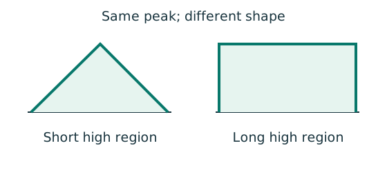
Prediction, then explanation. Two segments can have equal peak moment but different distributions. Their equivalent moment factors can therefore differ.
Evaluate moments from the true whole-beam analysis at the required positions. Apply the exact table’s weights, signs and lower bound.
mLT is an LTB factor. mx and my belong to the specified flexural checks. They are not interchangeable.
Scope. Some rules use magnitudes; others require signed ordinates. A factor does not reduce the actual moment used in a local section check.
Check and takeaway. Measure quarter points from the segment start, not automatically from the beam’s left support.
Shear and bending share the web
Decide whether the unreduced bending resistance remains applicable at the section being checked.
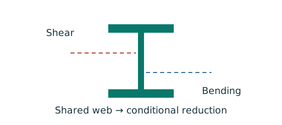
Prediction, then explanation. Raising shear beyond the specified threshold can reduce available bending resistance. A distant maximum shear is not the coexistent shear.
Find the moment-check position. Evaluate the shear there. Compare it with the low-shear threshold before selecting the resistance expression.
V is shear at the checked section; Vc is its shear resistance. Both use the same force unit.
Scope. Above the threshold, use the supplied reduction expression. The threshold itself is not a substitute resistance formula.
Check and takeaway. If the maximum shear anywhere is below the threshold, all sections satisfy that low-shear condition. Otherwise check the actual positions.
Apply the reasoning to this section’s data and conditions
P11 · off-centre load
Prediction and explained answer.
A6 m simple beam carries a design point load from A.
Ignore self-weight.
Find reactions, maximum moment and full-span quarter-point .
Hint
The quarter points are ,,.
Derive their moments rather than using a central-load shortcut.
Answer and reasoning
givesRB50 kN; RA100 kN.
Mmax atx 2 is .
; ; .
Equivalent demand .
The central-point shortcut does not match this load position.
Mechanism detailsBalance reactions and moments
The complete mechanism is explained below.
Read each stage together with its stated conditions; playback and interaction are not required.
This demonstrator is a simply supported 6 m beam with a 60 kN point load.
It is not the page’s original loading diagram.
.
Moving the load towards B increases .
.
The two upward reactions must sum to P.
With the load at midspan, .
End couples, UDLs and overhangs require their own equilibrium terms.
P12 · high-shear variant
Independent practice.A section has , , , , .
It is Class 1.
Find the reduced .
Hint
Useρ and both reduced expressions including the ceiling.
Answer and reasoning
.
First resistance term: Upper bound: .
Demand fails, even though the original low-shear resistance was .
Mechanism detailsHigh shear reduces bending resistance
The complete mechanism is explained below.
Read each stage together with its stated conditions; playback and interaction are not required.
- Part of the web contributes to bending while also carrying shear.
The course low-shear route applies at .
Above it, follow the applicable reduction expression.
- The highlighted web contribution is reduced, not the complete cross-section by an arbitrary percentage.
- Retain the section-class-specific formula and all bounds shown in the original calculation.
P13 · load increase
Independent practice.Imposed-load-only deflection is , limit .
Only increases by , is unchanged.
A student multiplies all ULS internal forces by .
Correct the calculation.
Hint
Elastic deflection is linear in its load.
However, the ULS total contains an unchanged dead component.
Answer and reasoning
New deflection , so SLS fails.
New ULS actions , not .
Separate the / contributions and recalculate reactions and moments.
Mechanism detailsSee stiffness and deflection
The complete mechanism is explained below.
Read each stage together with its stated conditions; playback and interaction are not required.
Use the specified SLS load, span and support arrangement.
The demonstrator has a full-span UDL.
The loaded beam bends.
The deformation is exaggerated so its shape can be seen.
For a simply supported full-span UDL, .
Double L with w, E and I unchanged: δ becomes 16 times as large.
The readout uses , and .
Select the finish/support-specific limit from the original table.
P14 · unknown restraint
Prediction and explained answer.
A beam’s strength calculation passes only ifLE=L.
The drawing shows end supports but no lateral detail or load-height statement.
What is a complete conclusion?
Hint
An assumption is not a dimension inferred from a line drawing.
Answer and reasoning
State the calculated result conditional on the normal-load/end-restraint modelLE=L.
Identify the needed lateral/torsional restraint and load-height information.
RecalculateLE from the applicable course condition if those differ.
Do not invent a restraint and report unconditional adequacy.
P15 · weak-axis tie
Prediction and explained answer.
AUC hasrx 120 mm,ry 60 mm, actual length .
Both ends pinned.
A midheight tie restrains only weak-axis lateral displacement.
Findλx andλy.
Hint
A tie changes only the restrained buckling direction.
Answer and reasoning
LEx 4000,L Ey 2000 mm; , .
Equal slenderness does not prove equalpc because the selected curves may differ.
Read the correct curve for each axis.
Mechanism detailsEffective length and buckling axes
The complete mechanism is explained below.
Read each stage together with its stated conditions; playback and interaction are not required.
- A column can bow sideways before its section reaches the crushing resistance.
- Each axis has its own radius of gyration and restraint spacing.
, with compatible length units.
A tie affects only the directions it actually restrains.
Select each buckling curve and compressive strength before forming Pc.
The governing axis is determined by resistance, not slenderness alone.
P16 · rectangle becomes a U
Prediction and explained answer.
A four-sided rectangular weld loses its top horizontal run.
Can you use the same centroid andIx+Iy?
Hint
Changing effective weld geometry changes both direct stress and torsion.
Answer and reasoning
The old four-sided result no longer applies.
Removing a side reduces total weld length.
The length-weighted centroid moves toward the remaining bottom run.
Recalculate centroidΣLi yi/ΣLi.
Calculate each remaining line inertia about that centroid using parallel-axis terms; recompute from the force line to the new centroid.
Combine direct and torsional components at candidate extreme points.
Use the new three-sided geometry for each line-inertia calculation.
Mechanism detailsBalance reactions and moments
The complete mechanism is explained below.
Read each stage together with its stated conditions; playback and interaction are not required.
This demonstrator is a simply supported 6 m beam with a 60 kN point load.
It is not the page’s original loading diagram.
.
Moving the load towards B increases .
.
The two upward reactions must sum to P.
With the load at midspan, .
End couples, UDLs and overhangs require their own equilibrium terms.
How to know you can apply the method independently
Make the next decision from the known conditions
Read the specific task below and identify the quantity or explanation it asks for.
Prediction, then explanation. Changing a load value may preserve the method. Changing the support or failure mechanism can require a different method.
Separate given, lookup, calculated and assumed values. State why the model applies. Keep necessary intermediate steps and units beside the equations.
A conditional answer states the exact condition required for its conclusion. It does not fill missing data with a guess.
Scope. A repeated result is not an independent verification. Use equilibrium, dimensions, a reverse substitution or an appropriate limiting case.
Check and takeaway. The explanation and answer are shown together in this edition. No response, score or completed interaction is needed to continue.
Apply the reasoning to this section’s data and conditions
Pass a stage only after solving its calculations with units and explaining each applicability choice without revealing the answer.
After a failed attempt, read one relevant worked example, then solve a different question rather than immediately copying the same one.
Use the timed mock only after you can complete Stage 3 without hidden assumptions.
Take the full timed mock · Return to every lecture/tutorial example
Mechanism detailsFollow the calculation sequence
The complete mechanism is explained below.
Read each stage together with its stated conditions; playback and interaction are not required.
- Locate the load, supports, connection geometry and any stated assumptions.
- Keep given values, table lookups and calculated values distinct; reconcile their units.
- The calculation player steps through the existing expressions in their original order.
Compare demand with resistance or the relevant limit.
Keep missing inputs and conditional conclusions explicit.