Connection example 4: bracket bolts in shear and tension
← Read this lecture example beside its chapter concepts
Check ten Grade 8.8 M16 bolts supporting a ultimate bracket load at eccentricity. Five bolts are arranged vertically on each side at centres. Steel is S355.
Original source: LectureNotes/Ch 2_Connection.pdf — p. 27, p. 28.
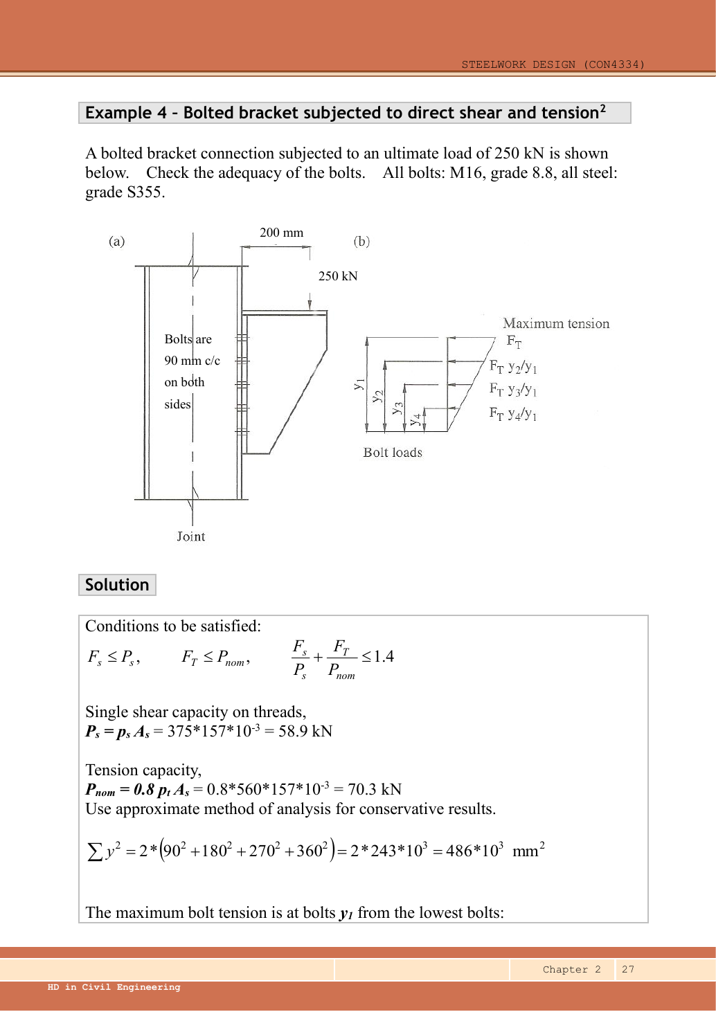
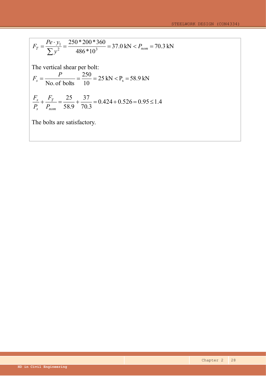
A given value comes from the question or diagram.
A lookup value comes from the named table.
A calculated value follows from the working.
Each assumption is stated where the calculation needs it.
Known information, diagram labels and unknowns
An eccentric bracket pulls bolts differently
An out-of-plane moment rotates the bracket about the stated pivot. Determine the bolt tension pattern.
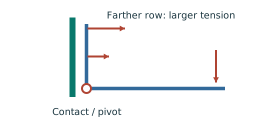
Prediction, then explanation. For unchanged geometry, doubling the applied moment doubles the modelled bolt tensions. Changing the pivot changes the distribution.
Use compatibility to relate tension to distance. Moment equilibrium then determines the proportionality factor.
M is moment in kN·mm. yi is distance from the stated pivot in mm. Ft,i is tension in kN.
Scope. Apply only to the stated active bolt set and pivot model. Flexible plates can create prying; use the supplied assumptions and resistance definitions.
Check and takeaway. A bolt’s lever arm is measured from the pivot used in the equation. It is not automatically its distance from the group centroid.
A table value has conditions
Find a design property without mixing a row, column or standard from a different case.
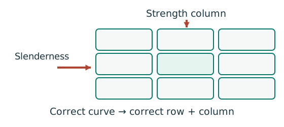
Prediction, then explanation. A different flange thickness can select a lower design strength even when the steel grade name remains unchanged.
Match the complete section designation. Read the relevant axis and unit. For strength tables, select material, thickness and curve before interpolating.
Given values come from the question. Lookup values come from a named table. Assumed values require an explicit condition.
Scope. A missing row or omitted restraint cannot be recovered from a schematic’s scale. Keep the result conditional when required data are absent.
Check and takeaway. Record the table, row, column and unit beside the substitution. That makes a later check possible.
Apply the reasoning to this section’s data and conditions
| Input | Origin |
|---|---|
| Given load | ultimate. The downward arrow is outside the connection plane. |
| Given bolt arrangement | Five bolts per side; two sides; between consecutive rows; total . |
| Calculated row distances | On each side, measure upwards from the bottom rotation line: . |
| Lookup | M16 , Grade 8.8 and (Ch 2 pp.3,9–10). |
| Model assumption | Rigid bracket and linear tensile-force distribution about bottom bolt line, as stated in the lecturer approximation. Use nominal tension . |
Why this method applies
Add force components at each bolt
An in-plane load acts away from the bolt-group centre. Find the largest resultant bolt force.
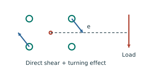
Prediction, then explanation. At fixed force, increasing eccentricity increases the moment component. Its direction differs between bolts.
Locate the bolt-group centre and coordinates. Add horizontal components together and vertical components together before finding each resultant.
e, xi and yi use mm; J uses mm². With M in kN·mm, each moment-force component is in kN.
Scope. These expressions use the stated elastic, equal-bolt in-plane model. Out-of-plane tension and prying require another model.
Check and takeaway. Do not add force magnitudes before resolving directions. Two perpendicular forces of 3 and 4 kN give 5 kN, not 7 kN.
Use the same mechanism: An eccentric bracket pulls bolts differently. For unchanged geometry, doubling the applied moment doubles the modelled bolt tensions. Changing the pivot changes the distribution.
Test every possible fracture cut
Find the remaining steel area across a candidate tension-failure path.
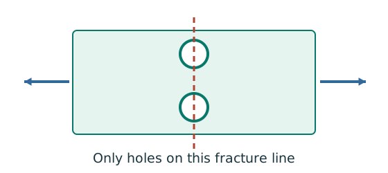
Prediction, then explanation. At fixed plate size, larger holes reduce the straight-path net area. A diagonal path needs its own stagger correction.
Subtract the hole widths crossed by the path, then multiply by thickness. Compare all plausible paths using the applicable course rule.
An is net area in mm²; b is plate width; d₀ is hole diameter; t is thickness, all in mm. n counts holes on this straight path.
Scope. This expression is for a straight cut. Effective area can require further shear-lag rules. Gross, net and effective areas must remain distinct.
Check and takeaway. Use the hole diameter, not the bolt diameter, when removing missing steel. The plate contains a hole, not solid steel around the bolt shank.
Apply the reasoning to this section’s data and conditions
The load pulls the upper bolts along their axes while all bolts carry vertical shear.
Use an out-of-plane rotation model, not the centroidal in-plane torsion formula.
Check shear, tension and their interaction separately.
The task’s bolt calculation does not provide the full plate/gauge dimensions needed for a complete joint/prying and bearing verification.
1. Find bolt shear and nominal tension resistance
Use the same mechanism: An eccentric bracket pulls bolts differently. For unchanged geometry, doubling the applied moment doubles the modelled bolt tensions. Changing the pivot changes the distribution.
Count cuts through each loaded bolt
Find how many shear planes transfer the force through one side of the connection.
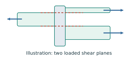
Prediction, then explanation. For equal sharing and unchanged bolt area, two active planes provide twice one plane’s shear resistance.
Select the area at the actual shear plane. Multiply by bolt shear strength. Count only the bolts and planes in the same transfer stage.
ps is bolt shear strength in N/mm²; As is the appropriate area in mm². nb counts bolts; ns counts equally loaded shear planes.
Scope. Use the thread area when threads cross the plane as required. Check bearing, plate failure and detailing separately.
Check and takeaway. Both halves of a butt splice carry the full transmitted force in sequence. Counting both halves together would double the apparent resistance.
Apply the reasoning to this section’s data and conditions
The reduction is part of the adopted simplified model.
Do not substitute in the nominal-tension interaction denominator.
Mechanism detailsOut-of-plane bolt tension and prying
The complete mechanism is explained below.
Read each stage together with its stated conditions; playback and interaction are not required.
- A bracket moment can create compression at the plate contact and tension in the bolt rows.
- The original assumed pivot/compression line determines each row distance.
Under the elastic row model, a farther tension row attracts more tension.
Direct shear may act simultaneously.
Flexible plates can add prying force.
Use nominal tension and interaction rules exactly as specified by the course.
2. Sum squared distances about the bottom row
Use the same mechanism: An eccentric bracket pulls bolts differently. For unchanged geometry, doubling the applied moment doubles the modelled bolt tensions. Changing the pivot changes the distribution.
Apply the reasoning to this section’s data and conditions
Each of the two vertical sides has the same distances.
The bottom row contributes to moment resistance but remains in the count for direct shear.
Mechanism detailsOut-of-plane bolt tension and prying
The complete mechanism is explained below.
Read each stage together with its stated conditions; playback and interaction are not required.
- A bracket moment can create compression at the plate contact and tension in the bolt rows.
- The original assumed pivot/compression line determines each row distance.
Under the elastic row model, a farther tension row attracts more tension.
Direct shear may act simultaneously.
Flexible plates can add prying force.
Use nominal tension and interaction rules exactly as specified by the course.
3. Maximum tension is in the top row
Use the same mechanism: An eccentric bracket pulls bolts differently. For unchanged geometry, doubling the applied moment doubles the modelled bolt tensions. Changing the pivot changes the distribution.
Apply the reasoning to this section’s data and conditions
Physical interpretation: Why the top bolt row is pulled hardest
The bracket tries to peel away from the support about the assumed contact line.
Sketch, not to scale; use the original dimensions.
- Use the rotation/contact line assumed by the course model.
- Measure each bolt row’s distance from that line.
- Check maximum tension, direct shear and their interaction.
Remember: A row at the pivot can still carry direct shear.
Tension varies in proportion to distance .
Let ; moment equilibrium gives .
Thus and the top bolt at has the largest tension.
Mechanism detailsOut-of-plane bolt tension and prying
The complete mechanism is explained below.
Read each stage together with its stated conditions; playback and interaction are not required.
- A bracket moment can create compression at the plate contact and tension in the bolt rows.
- The original assumed pivot/compression line determines each row distance.
Under the elastic row model, a farther tension row attracts more tension.
Direct shear may act simultaneously.
Flexible plates can add prying force.
Use nominal tension and interaction rules exactly as specified by the course.
4. Uniform direct shear
Use the same mechanism: Count cuts through each loaded bolt. For equal sharing and unchanged bolt area, two active planes provide twice one plane’s shear resistance.
Apply the reasoning to this section’s data and conditions
Mechanism detailsCount the bolt shear planes
The complete mechanism is explained below.
Read each stage together with its stated conditions; playback and interaction are not required.
- Load must cross an interface between the connected plates.
- A lap joint gives one shear plane through a bolt.
A symmetric double-cover joint may provide two shear planes.
Count load-transfer interfaces, not just visible plates.
Use the source’s area and shear strength.
Then check bearing, plate resistance and detailing separately.
5. Combined action and conclusion
Use the same mechanism: An eccentric bracket pulls bolts differently. For unchanged geometry, doubling the applied moment doubles the modelled bolt tensions. Changing the pivot changes the distribution.
Two simultaneous actions use one component
Check a component that carries shear and tension, or compression and bending, at the same time.
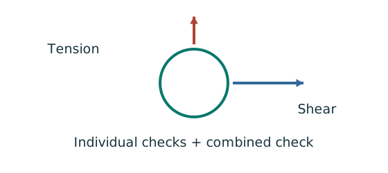
Prediction, then explanation. At fixed resistances, increasing one demand increases its utilisation. The permitted sum is not always one.
First apply the individual checks. Next use the exact combined equation and its definitions. Keep demands from the same load case.
This is the course bolt interaction rule. Fs and Ft are bolt demands; Ps and Pnom are their specified resistance denominators.
Scope. The 1.4 limit and nominal tension denominator do not apply to column equations. Their limits and moment definitions are separate.
Check and takeaway. A sum above one can pass this bolt rule while still needing individual checks. A pass must name the actual equation used.
Apply the reasoning to this section’s data and conditions
Physical interpretation: Two passing checks may still interact
One bolt is doing two jobs at the same time.
Sketch, not to scale; use the original dimensions.
- Check shear on its own and tension on its own.
- Calculate the course’s combined-action expression.
- Apply its own limit, not a limit borrowed from columns.
Remember: The supplied bolt interaction limit of 1.4 does not replace the individual checks.
The bolts satisfy all three calculated shear/tension conditions under the lecturer’s approximate model.
This is the requested bolt result.
The source does not give sufficient plate thickness, bearing-edge geometry or flange gauge.
Therefore the result does not establish the other joint limit states.
Mechanism detailsOut-of-plane bolt tension and prying
The complete mechanism is explained below.
Read each stage together with its stated conditions; playback and interaction are not required.
- A bracket moment can create compression at the plate contact and tension in the bolt rows.
- The original assumed pivot/compression line determines each row distance.
Under the elastic row model, a farther tension row attracts more tension.
Direct shear may act simultaneously.
Flexible plates can add prying force.
Use nominal tension and interaction rules exactly as specified by the course.
Result and concise exam wording
Use the same mechanism: Two simultaneous actions use one component. At fixed resistances, increasing one demand increases its utilisation. The permitted sum is not always one.
Apply the reasoning to this section’s data and conditions
; .
about bottom bolt line.
.
.
Individual limits pass and interaction.
Bolts are adequate under the specified approximate shear/tension model.
Misconceptions and checks
Use the same mechanism: Two simultaneous actions use one component. At fixed resistances, increasing one demand increases its utilisation. The permitted sum is not always one.
Apply the reasoning to this section’s data and conditions
- Do not factor again.
- Do not measure from the group centroid for this bottom-pivot model.
- Do not omit the bottom bolts from direct shear.
- Passing the interaction does not replace individual shear/tension limits.
How the method transfers to a new variant
Use the same mechanism: An eccentric bracket pulls bolts differently. For unchanged geometry, doubling the applied moment doubles the modelled bolt tensions. Changing the pivot changes the distribution.
Use the same mechanism: Test every possible fracture cut. At fixed plate size, larger holes reduce the straight-path net area. A diagonal path needs its own stagger correction.
Use the same mechanism: Two simultaneous actions use one component. At fixed resistances, increasing one demand increases its utilisation. The permitted sum is not always one.
Apply the reasoning to this section’s data and conditions
- Identify out-of-plane rotation and the stated pivot.
- Write all distances and include all physical bolts in .
- Calculate maximum tension and uniform shear.
- Check each individual resistance and then the interaction.
- State the model and any unprovided plate/prying information.
Prediction with explained answer
Use the same mechanism: Add force components at each bolt. At fixed force, increasing eccentricity increases the moment component. Its direction differs between bolts.
Use the same mechanism: Two simultaneous actions use one component. At fixed resistances, increasing one demand increases its utilisation. The permitted sum is not always one.
Apply the reasoning to this section’s data and conditions
Prediction and explained answer.
Move the same load to eccentricity.
Does the existing bolt group pass?
Answer and reasoning
Tension doubles to , exceeding .
Interaction becomes .
Both tension and interaction fail; shear remains .
Mechanism detailsOut-of-plane bolt tension and prying
The complete mechanism is explained below.
Read each stage together with its stated conditions; playback and interaction are not required.
- A bracket moment can create compression at the plate contact and tension in the bolt rows.
- The original assumed pivot/compression line determines each row distance.
Under the elastic row model, a farther tension row attracts more tension.
Direct shear may act simultaneously.
Flexible plates can add prying force.
Use nominal tension and interaction rules exactly as specified by the course.