Simple-construction column: how beam reactions produce moments (Beam Reactions into Columns)
Task: Connect the load line, column centre, segment stiffnesses and section interaction expression.
Go straight to Step 1 ↓Design flow for this type of question: Column: axial force with moments →
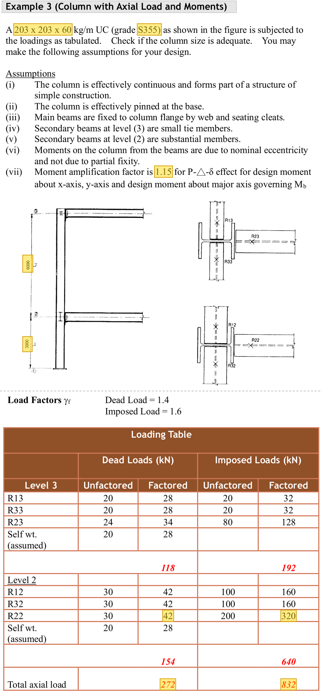
The question in short: A main beam delivers reactions of 42 kN and 320 kN to the side of a 203×203×60 UC column, not at its centre, so the column bends. The column lengths above and below are 6000 and 3000 mm. Find the column moment and do the section check.
What differs from the previous example of this type: In the previous example the column lengths above and below had equal stiffness and shared the moment equally. Here their lengths differ; the shorter length is stiffer and takes the larger share of the moment.
| Given | Value and Unit |
|---|---|
| Section | 203×203×60 UC, S355; |
| Beam-end reaction | Main beam R22: dead 42 kN, imposed 320 kN (factored, from the loading table) |
| Column segments | Same section; upper and lower lengths 6000 and 3000 mm |
| Data for the check | Total axial load 272 + 832 kN (loading table); amplification factor 1.15; ; , ; |
Yellow: values given in the question. The same values are marked where they are substituted in the steps below.
Orange box: values read directly from the Data File, the same values boxed orange in the lookup screenshots. A value interpolated between two table rows is a calculation, so it has no box.


Solution Route: Eccentricity →joint moment→upper/lower distribution→amplified demand→section comparison.
This browser cannot show the 3D model.
The beam reaction acts 100 mm from the column face, not at the column centre, so it causes a moment at the joint. The column lengths above and below share this moment in proportion to their stiffness.
- Beam reaction
- Eccentricity gives a joint moment→
- Shared by the column lengthsAbout 49.5 kNm in the shorter lower length; amplified to 56.925 kNm
- Cross-section check (axial force and moment)Sum 0.651Limit 1
- Step 1 · Measure eccentricity from the column centre
Why this step: The beam sits on the side of the column, so its reaction does not pass through the column centre. The further the force is from the centre, the more it bends the column, so this distance is needed first.
In simple construction the beam reaction is taken 100 mm from the column face (a rule in the lecture notes, not stated in the question); the eccentricity is measured from the column centre, so half the section depth is added. The lecturer rounds 204.8 to about 205 mm.
- Step 2 · Joint moment
Why this step: The off-centre reaction acts like a spanner on the column. Force times distance is the moment it puts into the column at the beam joint, which the column lengths above and below then share.
Convert mm to m before multiplying by kN.
Units: The eccentricity of 205 mm is divided by 1000 to give 0.205 m. kN times m gives kNm.
- Step 3 · Stiffness and distribution
Why this step: When the joint rotates, the column lengths above and below resist together. The stiffer one is harder to bend and so takes more of the moment, just as the stiffer of two springs takes more force.
For equal sections, rotational stiffness is proportional to . The shorter segment is stiffer and takes more moment. Use the lecturer's segment labels to identify each share; the length in the numerator is not necessarily the receiving segment's own length.
Where the numbers come from: from Step 2.
Load path · How a beam reaction bends the columnLeft, the column seen from above: the beam reaction acts 100 mm from the column face, about 205 mm from the centre, so it causes a moment = Re about the axis. Right, the elevation: the joint moment is shared by the column lengths above and below, and the shorter, stiffer length takes more. - Step 4 · Amplify governing demand
Why this step: The check uses the hardest-worked place, which is the end of the shorter column length. The amplification factor then adds the extra moment that appears when the compressed column deforms.
Use 1.15 here and the maximum end moment 49.5 for this demand.
New symbols in this step- , , : Two-axis and LTB governing moment demands; kNm
Where the numbers come from: from Step 3.
- Step 5 · Section axial-compression resistance
Why this step: This is the force at which all the steel in the section is compressed to , the limit for crushing the section. It is the denominator of the compression term in the next step.
Convert 76.4 cm² to mm² first. This is a section check only; member buckling is separate.
New symbols in this step- , , : Gross area mm²; yield and compression buckling strengths N/mm²
Units: of 76.4 cm² is multiplied by 100 to change it into mm². in N/mm² times mm² gives N, and dividing by 1000 gives kN.
Data file lookup · Data Page 1 · Design strength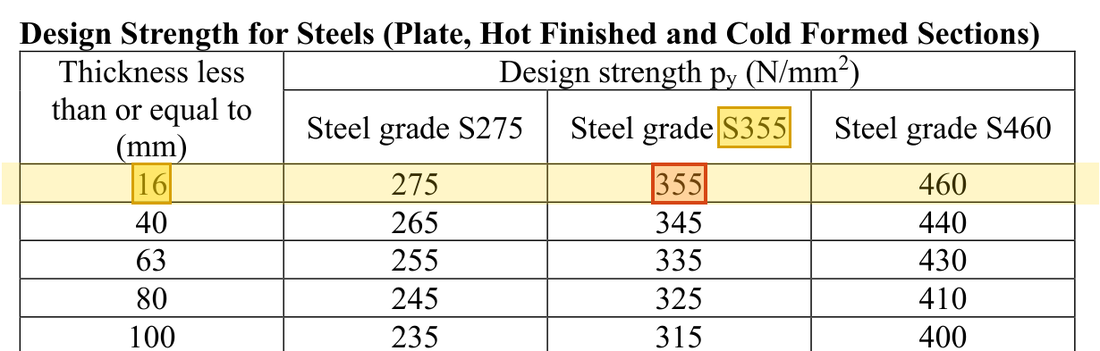
Flange thick: the row, S355 column gives . How the grade and thickness choose this row →Yellow: given parameter, row or columnOrange: value read from the table, boxed orange in the text too - Step 6 · This section check
Why this step: The column carries the compression from above together with the moment caused by the beam reaction. Each uses part of the section's strength; the total must be below 1 for the section not to be crushed.
The section moment capacity is the smaller of pySx and 1.2pyZx; the total axial load is 272 + 832 kN from the loading table.
New symbols in this step- , : Design axial force and buckling compression resistance; kN
- , , : Corresponding bending resistances; kNm, with different section/member definitions
Where the numbers come from: from Step 5; from Step 4.
Units: and are multiplied by 1000 to change cm³ into mm³, and times mm³ gives Nmm. Dividing by 1000000 gives kNm, so the formula divides by 1000.
Load path · How the ratios add upThis column has a moment about one axis only: blue is the share used by the axial force and green the share used by the moment. Together they must not pass the red dashed line.
The section passes. Effective lengths , buckling strengths and corresponding member-check data are still needed for an overall column verdict. Equal moment halves apply only to equal stiffness.
All the symbols of this example
| Symbols | Meaning and Units |
|---|---|
| , | Design axial force and buckling compression resistance; kN |
| , , | Gross area mm²; yield and compression buckling strengths N/mm² |
| , , | Two-axis and LTB governing moment demands; kNm |
| , , , | Two-axis plastic/elastic moduli; convert the tabulated cm³ |
| , , | Corresponding bending resistances; kNm, with different section/member definitions |
| , , | Total utilisations for the section and two member expressions; dimensionless |
Video positions: 24 October 02:45:00 · 24 October 02:50:00