Column interaction revision: where each ratio comes from (Column Interaction Review)
Task: Recalculate the three course ratios and confirm that they belong to the same member expression.
Go straight to Step 1 ↓Design flow for this type of question: Column: axial force with moments →
The question in short: A 305×305×158 UC column carries 3000 kN of compression with moments of 90 kNm in the direction and 60 kNm in the direction. Recalculate the three ratios of the member interaction check one by one and see whether they add up to less than 1.
What differs from the previous example of this type: Moments no longer come from eccentricity here; the moments, , and are all given. The point is to see how demand and capacity are paired in each term of one member check.
| Given | Value and Unit |
|---|---|
| Axial force | ; 305×305×158 UC, S355 |
| Section properties | , ; ; , |
| Buckling | (lecturer’s worksheet) |
| direction | Moment 90 kNm; amplification 1.1; (lecturer’s worksheet) |
| direction | Moment 60 kNm; amplification 1.15; (lecturer’s worksheet) |
Yellow: values given in the question. The same values are marked where they are substituted in the steps below.
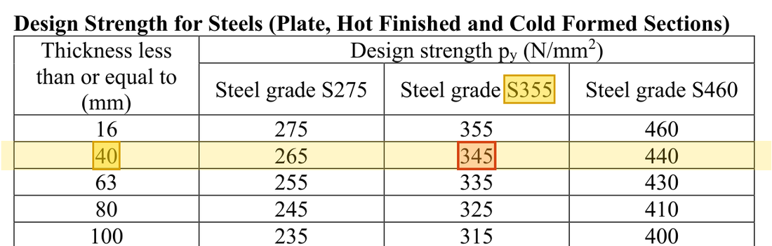
Orange box: values read directly from the Data File, the same values boxed orange in the lookup screenshots. A value interpolated between two table rows is a calculation, so it has no box.


Solution Route: Calculate →amplify each directional demand→apply moment factors→divide by resistance→add.
One column carries axial force and moments about both axes together. The three ratios are the three terms of one member check, added and compared with 1.
- Axial term3000 / 5014.95 ≈ 0.5982
- -axis moment term≈ 0.1102
- -axis moment term≈ 0.1064
- Sum of the three termsSum 0.815Limit 1
- Step 1 · Compression resistance
Why this step: The member check guards against the whole column becoming unstable, so the compression capacity must be , which allows for buckling. The weak axis bows most easily, so is read using .
Curve c about : lies between the 56 and 58 rows of Table 8.8(c), and interpolation gives ; 201 cm² is multiplied by 100 to give mm².
New symbols in this step- , , : Gross area mm²; yield and compression buckling strengths N/mm²
Units: of 201 cm² is multiplied by 100 to change it into mm². in N/mm² times mm² gives N, and dividing by 1000 gives kN.
Data file lookup · Data Page 8 · Table 8.8(c)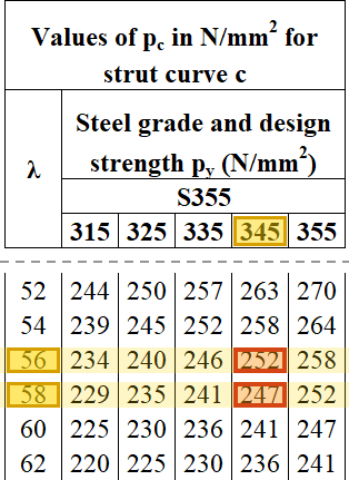
Table 8.8(c) ( axis, curve c), column: → 252 and → 247 N/mm²; interpolating at gives .Yellow: given parameter, row or columnOrange: value read from the table, boxed orange in the text too - Step 2 · Axial-force term
Why this step: This ratio is the share of the column's buckling capacity used by compression. It is more than half, so less than half is left for the two moment terms.
Use here, not .
New symbols in this step- , : Design axial force and buckling compression resistance; kN
Where the numbers come from: from Step 1.
- Step 3 · -bending term
Why this step: This ratio is the share used by the -axis moment. reduces the moment because the largest value does not act along the whole column; the capacity is the moment at which the outermost steel just yields.
Both amplification and moment-distribution factors act on demand.
New symbols in this step- , , : Equivalent moment-distribution factors; dimensionless
Units: is multiplied by 1000 to change cm³ into mm³. times mm³ gives Nmm, and dividing by 1000000 gives kNm. Together this is a division by 1000.
- Step 4 · -bending term
Why this step: The section is much weaker in bending about its weak axis. So although the -axis moment is smaller, it uses about the same share as the -axis moment.
Retain the axis's own factor, demand and resistance.
Units: is in cm³ and is multiplied by 1000 to give mm³. times mm³ gives Nmm, and dividing by 1000000 gives kNm, so the formula divides by 1000.
- Step 5 · Add and assess
Why this step: Compression and the two moments act on the same column at the same time, so their three shares are added. A total below 1 means the column stays stable under all three together.
The three terms add up to about 0.8148; the 0.8149 on the lecturer’s sheet is only a rounding difference and does not change the comparison.
Where the numbers come from: from Step 2; from Step 3; from Step 4.
Load path · How the ratios add upEach bar is one check: blue is the share used by the axial force, green and yellow the shares used by the moments about the two axes. Together they must not pass the red dashed line.
This member expression passes. It does not establish that every column check is complete, and must not be mixed with the separate 3500 kN problem.
All the symbols of this example
| Symbols | Meaning and Units |
|---|---|
| , | Design axial force and buckling compression resistance; kN |
| , , | Gross area mm²; yield and compression buckling strengths N/mm² |
| , , | Two-axis and LTB governing moment demands; kNm |
| , , , | Two-axis plastic/elastic moduli; convert the tabulated cm³ |
| , , | Equivalent moment-distribution factors; dimensionless |
Video positions: 14 November 01:20:00