6 m revision beam: coexisting shear and deflection (Coexistent Shear)
Task: Use overall maximum shear, shear at maximum moment and SLS loading separately.
Go straight to Step 1 ↓Design flow for this type of question: Laterally restrained beam →
The question in short: A 6 m beam uses a 406×178×74 UB in S355. The largest shear is 77.91 kN, the largest moment is 229.1 kNm with a shear of 74.80 kN at that point, and the imposed midspan point load is 47.25 kN. Check shear, moment and deflection.
What differs from the previous example of this type: The previous example was a local web check at a support. This one returns to whole-beam checks, and separates the largest shear in the beam from the shear at the point of largest moment.
| Given | Value and Unit |
|---|---|
| ULS | ; where (lecturer’s worksheet) |
| Section | 406×178×74 UB, S355; , ; , ; ; |
| SLS | Midspan ; ; |
Yellow: values given in the question. The same values are marked where they are substituted in the steps below.
Orange box: values read directly from the Data File, the same values boxed orange in the lookup screenshots. A value interpolated between two table rows is a calculation, so it has no box.
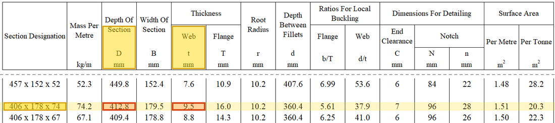
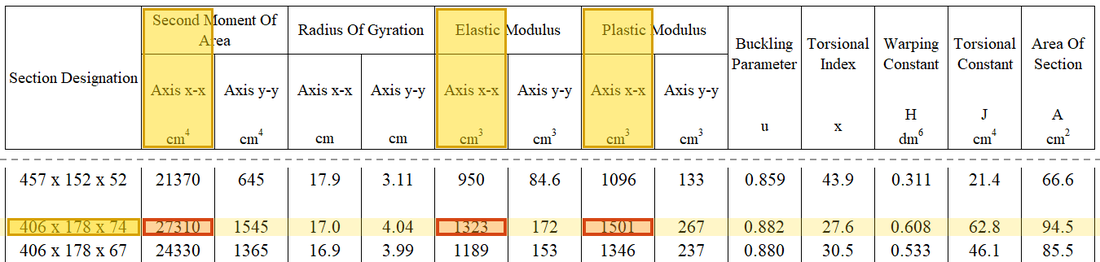
Solution Route: Overall shear→low shear at maximum moment→bending→unfactored deflection .
The beam takes the load to its two supports. Shear is largest at the supports and moment at midspan; each is checked with the values at its own position.
- Forces from the class sheet;
- Shear (supports)Demand 77.91 kNCapacity 803.77 kNUtilisation 0.10
- Bending (midspan)Demand 229.1 kNmCapacity 532.9 kNmUtilisation 0.43 · closest to the limit
- Deflection (SLS point load)Demand 3.8 mmCapacity 16.67 mmUtilisation 0.23
- Step 1 · Overall shear check
Why this step: The section with the largest shear is the one most likely to fail in shear, so the largest shear in the beam is compared with the web's shear capacity.
For a rolled section ; find first, then compare it with the beam’s .
New symbols in this step- , , : Section bending resistance in kNm, shear resistance in kN, LTB resistance in kNm
- , , , : Shear area mm², second moment of area mm⁴, plastic/elastic moduli mm³
- , , : Design yield/bending buckling strength and elastic modulus; N/mm²
Units: N/mm² times mm² gives N. Dividing by 1000 gives kN (1 kN is 1000 N), so it can be compared with the shear in kN.
- Step 2 · Coexisting shear
Why this step: Shear weakens bending strength, but only at the same section. So the shear at the point of largest moment matters here, not the largest shear in the beam.
Use 74.80 at the maximum-moment section to decide whether high-shear reduction is needed there.
New symbols in this step- , : Moment demand in kNm; shear demand in kN
Where the numbers come from: from Step 1.
- Step 3 · Bending
Why this step: This guards against yielding at the section with the largest moment. The capacity is more than twice the demand, so the beam has plenty of margin in bending.
Once the conditions are satisfied, select the smaller candidate and compare.
Units: N/mm² times cm³, divided by 1000, gives kNm: 1 cm³ is 1000 mm³ and 1 kNm is 1000000 Nmm, which together leave a division by 1000.
- Step 4 · Deflection units
Why this step: This finds how far the beam sags at midspan under the everyday imposed load. With every value in N and mm, the answer comes out directly in mm.
Use , and . is the SLS point load, not a ULS internal-action value.
New symbols in this step- , : Deflection mm; demand/resistance utilisation is dimensionless
Units: 47.25 kN times 1000 gives 47250 N and 6 m gives 6000 mm. in cm⁴ times 10^4 gives mm⁴, because 1 cm is 10 mm, multiplied four times.
Data file lookup · Data Page 1 · Steel properties
Data Page 1, steel properties: modulus of elasticity (printed as 205,000).Yellow: given parameter, row or columnOrange: value read from the table, boxed orange in the text too - Step 5 · Limit
Why this step: The sag is far below the limit, so the beam is stiff enough in use and will not make the floor dip noticeably or crack the finishes.
.
New symbols in this step- , , : Span in m or mm; end reactions in kN
Units: The 6 m span times 1000 gives 6000 mm, because 1 m is 1000 mm; the limit is therefore in mm too.
Data file lookup · Data Page 2 · Table 5.1 Deflection limits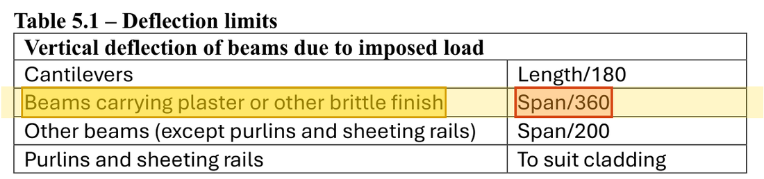
For beams carrying plaster or other brittle finish, the imposed-load deflection limit is span/360.Yellow: given parameter, row or columnOrange: value read from the table, boxed orange in the text too
The checks shown pass. A complete design also needs the stability checks for the full load model in the original question.
All the symbols of this example
| Symbols | Meaning and Units |
|---|---|
| , , | Area load kN/m², line load kN/m, point load kN |
| , , | Span in m or mm; end reactions in kN |
| , | Moment demand in kNm; shear demand in kN |
| , , | Section bending resistance in kNm, shear resistance in kN, LTB resistance in kNm |
| , , , | Overall depth, classification web depth, web thickness and flange thickness; mm |
| , , , | Shear area mm², second moment of area mm⁴, plastic/elastic moduli mm³ |
| , , | Design yield/bending buckling strength and elastic modulus; N/mm² |
| , | Deflection mm; demand/resistance utilisation is dimensionless |
Video positions: 14 November 01:55:00