Eccentric weld Q6: from geometry to resultant (Eccentric Weld Group)
Task: Understand eccentricity , line-group second moments and vector combination rather than adding component magnitudes directly.
Go straight to Step 1 ↓Design flow for this type of question: Fillet-welded connection →
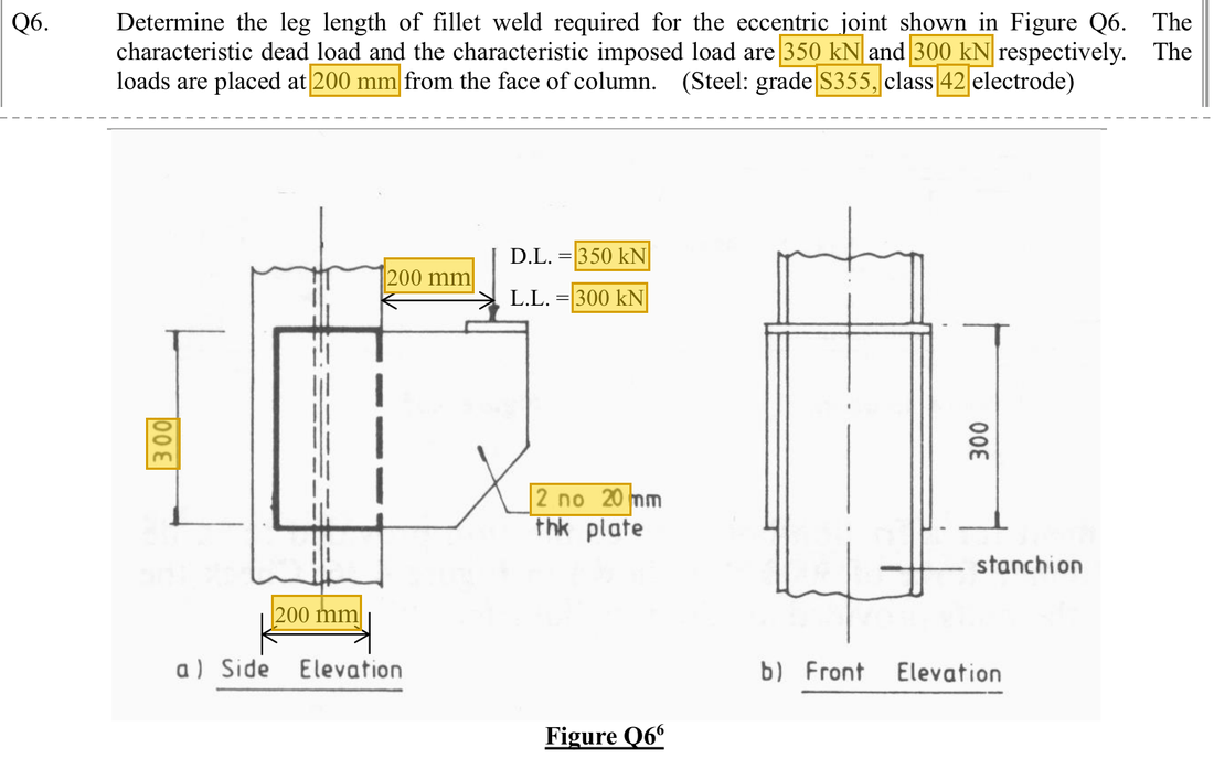
The question in short: A load (dead 350 kN, imposed 300 kN) acts 200 mm from the column face and is shared equally by two 20 mm side plates. Each plate is welded all round, 200 mm wide and 300 mm high. Find the force per mm at the most heavily loaded point of the weld and the leg size needed.
What differs from the previous example of this type: In the earlier examples the force passed through the centroid of the welds. Here the load sits to one side of the weld group, so the welds resist twisting as well as direct shear, and the two parts are combined by direction, not simply added.
| Given | Value and Unit |
|---|---|
| Loading | DL 350, LL 300 kN; two 20 mm side plates each carry half |
| Geometry | Load 200 mm from the column face; each side plate is welded on four sides, weld group 200 mm wide and 300 mm high |
| Material | S355, class 42 electrode; |
Yellow: values given in the question. The same values are marked where they are substituted in the steps below.
Orange box: values read directly from the Data File, the same values boxed orange in the lookup screenshots. A value interpolated between two table rows is a calculation, so it has no box.
Solution Route: Total design force→one-side force→centre/eccentricity →direct shear →torsional component→resultant →required leg size .
This browser cannot show the 3D model.
The load is first shared equally by the two side plates. The force on each plate misses the centroid of the weld group, so the welds resist a torque as well as direct shear.
- Design load970 kN, 485 kN per side plate
- Side plate: eccentricity gives a torque,
- Weld group: direct shear0.485 kN/mm, uniform all round
- Weld group: torsional shear1.26 kN/mm at the farthest corner
- Resultant and leg size1.58 kN/mm; a leg of about 9.04 mm is needed
- Column flangeReceives the load from the weld groups on both sides
- Step 1 · Total force and side allocation
Why this step: The rest of the calculation looks at the weld group on one side plate only, so the factored force taken by one group must be known first.
Combine loads to obtain 970 kN, then divide symmetrically into 485 kN per side.
New symbols in this step- , : Unfactored dead and imposed loads; kN
- Step 2 · Measure eccentricity from the centre
Why this step: The load does not pass through the centroid of the weld group, so it tries to turn the group about that centroid. A larger eccentricity means a larger twisting moment, which is why the distance is measured to the centroid.
200 mm reaches only the group edge; add half-width 100 mm.
New symbols in this step- , : Eccentricity and weld-group corner radius; mm
Where the numbers come from: from Step 1.
- Step 3 · Direct-shear distribution
Why this step: This is the force the weld would feel if the load passed exactly through the centroid: the whole group is sheared together in the direction of the load, and every millimetre takes the same force.
Each side plate is welded on four sides, so the total weld length is the perimeter of the weld group; sharing the load over that length gives kN per mm.
New symbols in this step- , : Leg size and effective throat; mm, with in this course
- , : Actual or effective weld length; mm, as identified by each step
- , : Applied force; kN
- , : Width and height of the rectangular weld group; mm
Where the numbers come from: from Step 1.
- Step 4 · Rectangular line-group
Why this step: The second moment measures how far the weld lies from the centroid and so how well it resists turning. The farther out the weld is, the larger the value and the smaller the force caused by twisting.
Width 200 and height 300 mm: add the two vertical lines' own second moments and the parallel-axis terms of the horizontal lines.
New symbols in this step- , , : Line-group second moments in this problem; mm³,
- Step 5 · Rectangular line-group
Why this step: Under twisting the weld group turns in its own plane about the centroid, so distances in both directions matter. The two second moments are therefore added before the twisting force is worked out.
Exchange horizontal and vertical roles, then add for , consistent with the course's rounded 2.08×10⁷.
Where the numbers come from: from Step 4.
- Step 6 · Line-group
Why this step: Twisting turns the weld about its centroid. Points farther from the centroid move more and take more force, so only the farthest corner needs checking; that is where the force from twisting is greatest.
is the distance from the centroid of the weld group to the farthest corner: half width 100 mm, half height 150 mm. The course treats the welds as lines of unit throat , so has units of mm³.
- Step 7 · Use the included angle for the resultant
Why this step: The weld at the corner feels the direct shear and the twisting force at the same time. They point in different directions, so the true demand per millimetre is their combined force, found by taking direction into account.
The two components do not act along one line. is perpendicular to , and the cosine of its angle with the vertical equals the half width 100 mm divided by .
New symbols in this step- , , : Direct, torsional and resultant force per millimetre; kN/mm
Where the numbers come from: from Step 6; from Step 3; from Step 6.
Load path · Eccentric load = direct shear + torsional shearThe method is the same as for an eccentric bolt group, with “force per bolt” replaced by “force per mm of weld”. The four corners are shown: ② the direct shear is the same all round; ③ the torsional shear is perpendicular to the radius and largest at the corners, the farthest points; ④ the corners on the load side take the largest resultant. - Step 8 · Calculate required leg size
Why this step: A larger leg size gives a thicker throat and more capacity per millimetre. Here the calculation is turned round to find the smallest leg at which the throat is just not sheared.
With , convert force-per-millimetre demand into leg size . The lecturer does not select a final size in class.
New symbols in this step- , : Weld design strength N/mm²; resistance per millimetre kN/mm
Where the numbers come from: from Step 7.
Units: is in kN/mm; multiplying by 1000 gives N/mm. Dividing by in N/mm² gives the throat in mm, and dividing by 0.7 gives the leg size in mm.
Data file lookup · Data Page 3 · Design strength of fillet weld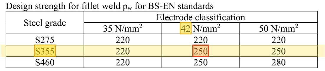
For S355 steel with class 42 electrodes the fillet weld design strength is .Yellow: given parameter, row or columnOrange: value read from the table, boxed orange in the text too
Approximately 9.04 mm is the requirement. The provided leg must be at least this large, with plate-thickness and detailing checks completed.
All the symbols of this example
| Symbols | Meaning and Units |
|---|---|
| , | Leg size and effective throat; mm, with in this course |
| , | Weld design strength N/mm²; resistance per millimetre kN/mm |
| , | Actual or effective weld length; mm, as identified by each step |
| , | Applied force; kN |
| , | Eccentricity and weld-group corner radius; mm |
| , , | Direct, torsional and resultant force per millimetre; kN/mm |
| , , | Line-group second moments in this problem; mm³, |
| , | Unfactored dead and imposed loads; kN |
| , | Width and height of the rectangular weld group; mm |
Video positions: 3 October Recording A 01:10:00 · 3 October Recording A 01:25:00 · 3 October Recording B 01:05:00 · 3 October Recording B 01:20:00