350 kN double angles: total areas and side distribution (Double Angles)
Task: Keep totals for both angles distinct from per-angle values while completing member resistance and weld length.
Go straight to Step 1 ↓Design flow for this type of question: Fillet-welded connection →
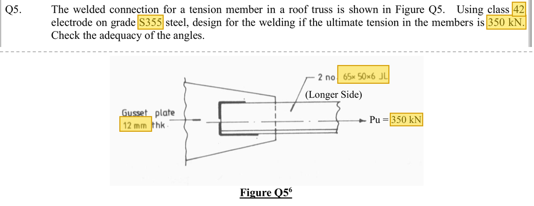
The question in short: Two 65×50×6 angles are welded by their long legs to either side of a 12 mm gusset plate and together carry an ultimate tension of 350 kN, using 6 mm fillet welds. Check that the angles are not pulled apart, then decide the weld length on each side of each angle.
What differs from the previous example of this type: The previous example had one angle. Here there are two, so the areas are added, and the total weld length is first halved between the angles and then split by the centroid within each angle. The tension is already an ultimate value, so no load factors are applied.
| Given | Value and Unit |
|---|---|
| Members | Two 65×50×6 angles connected by the long leg, S355, on both sides of a 12 mm gusset plate |
| Loading | Ultimate tension 350 kN |
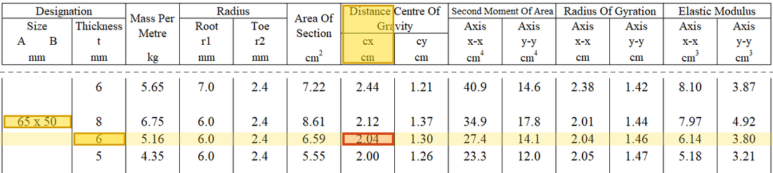
| Weld data | Try a 6 mm fillet weld; class 42 electrode, ; angle centroid 20.4 mm from the back of the long leg |
Yellow: values given in the question. The same values are marked where they are substituted in the steps below.
Orange box: values read directly from the Data File, the same values boxed orange in the lookup screenshots. A value interpolated between two table rows is a calculation, so it has no box.
Solution Route: Total-area resistance→total weld length→divide between angles→balance each angle's sides→actual lengths.
This browser cannot show the 3D model.
The 350 kN is shared equally by the two angles; each angle passes its half through welds and into the gusset between them.
- Ultimate tension350 kN
- Two angles in tension (together)Demand 350 kNCapacity 434.307 kNUtilisation 0.81
- Weld on side of each angleNeeds 126.359 mmUse 130 mm
- Weld on side of each angleNeeds 64.308 mmUse 65 mm
- 12 mm gussetReceives the whole 350 kN from the welds on its two faces
- Step 1 · Total area
Why this step: Whether the angles are pulled apart depends on the area of steel in tension. The connected and unconnected leg areas are kept separate so that the next step can discount only the unconnected legs.
Measure each leg to the thickness centreline: long leg 65 − 6/2 = 62 mm, short leg 50 − 6/2 = 47 mm; multiply by the thickness and by two angles. and already include both angles, so the capacity is not multiplied by 2 again.
New symbols in this step- , : Eccentricity and weld-group corner radius; mm
- , , : Connected/outstanding angle-leg areas mm²; tension resistance kN
- Step 2 · Double-angle expression for this problem
Why this step: This confirms the two angles together will not be pulled apart. With one angle on each side of the gusset plate the pull is more symmetric, so the unconnected legs are discounted less than for a single angle.
Use the lecturer's 0.15 outstanding-leg reduction, distinct from a single angle's 0.3.
Where the numbers come from: from Step 1; from Step 1.
Units: The combined area in mm² times in N/mm² gives N. Dividing by 1000 turns N into kN so it can be compared with 350 kN.
Data file lookup · Data Page 2 · Tension members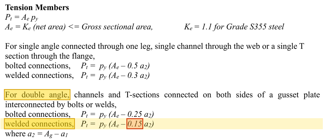
For double angles welded on both sides of a gusset plate, .Yellow: given parameter, row or columnOrange: value read from the table, boxed orange in the text too Data file lookup · Data Page 1 · Design strength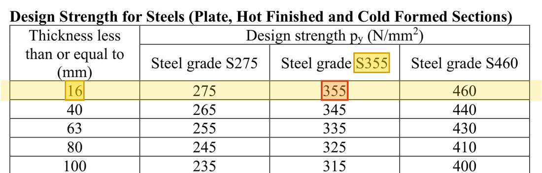
Angle 6 mm thick: the row, S355 column gives . How the grade and thickness choose this row →Yellow: given parameter, row or columnOrange: value read from the table, boxed orange in the text too - Step 3 · Total effective weld length
Why this step: All the tension must pass through the welds into the gusset plate. The result is the least load-carrying length for every weld on both angles together; with less, the weld throat would shear.
350 is already factored. A 6 mm leg provides 1.05 kN per millimetre.
New symbols in this step- , : Weld design strength N/mm²; resistance per millimetre kN/mm
- , : Applied force; kN
Units: Leg size in mm times 0.7 gives the throat in mm; times in N/mm² gives N per mm. Dividing by 1000 gives kN/mm. Then kN divided by kN/mm gives mm.
Data file lookup · Data Page 3 · Design strength of fillet weld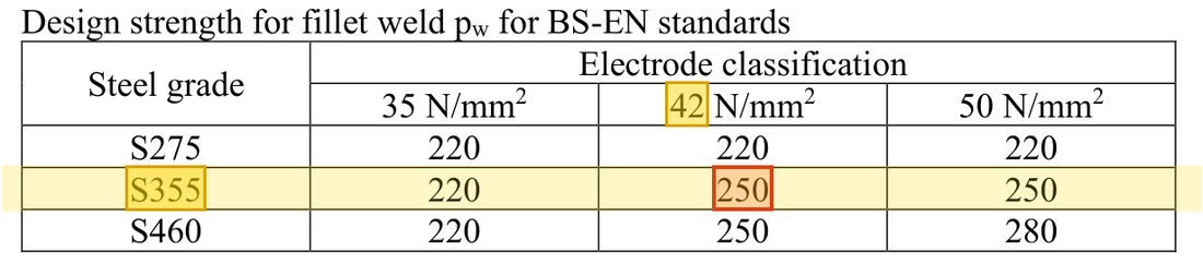
For S355 steel with class 42 electrodes the fillet weld design strength is .Yellow: given parameter, row or columnOrange: value read from the table, boxed orange in the text too - Step 4 · Per angle
Why this step: The two angles are identical and each carries half the tension, so each needs half the weld length. The split that follows looks at one angle only.
The angles share symmetrically. This row is length in mm. The original worksheet's kN label is dimensionally inconsistent; the preceding step establishes mm.
Where the numbers come from: from Step 3.
- Step 5 · Weld lengths on both sides
Why this step: The pull in each angle acts along its own centroid line. The edge nearer the centroid takes more force and gets the longer weld, so the combined weld force lines up with the centroid line.
The centroid is 65 − 20.4 = 44.6 mm from the other edge; balance about the centroid of one angle.
New symbols in this step- , : Distances from the two welds to the angle centroid; mm
Where the numbers come from: from Step 4.
Load path · How the two welds share the tensionThe two angles are symmetrical and each takes half the force. Each is then treated like a single angle: the effective weld length is split between sides and by the position of the centroid. Lengths shown are before adding . - Step 6 · Actual lengths and end returns
Why this step: The effective length plus the uncounted ends gives the length to be welded. The return weld carries the weld round the corner so that the weld end is not the first place to crack.
Add 12 mm to each side and round up to 130 and 65 mm. The course also provides 15 mm end returns.
New symbols in this step- , : Leg size and effective throat; mm, with in this course
434.307 kN is tension resistance of the double-angle member. 130/65 mm are actual lengths on each angle's two sides. Clear quantity levels and units prevent repeated multiplication or division by 2.
All the symbols of this example
| Symbols | Meaning and Units |
|---|---|
| , | Leg size and effective throat; mm, with in this course |
| , | Weld design strength N/mm²; resistance per millimetre kN/mm |
| , | Applied force; kN |
| , | Eccentricity and weld-group corner radius; mm |
| , , | Connected/outstanding angle-leg areas mm²; tension resistance kN |
| , | Distances from the two welds to the angle centroid; mm |
Video positions: 3 October Recording A 00:40:00 · 3 October Recording A 00:50:00 · 3 October Recording A 01:00:00 · 3 October Recording B 00:45:00