Q5: utilisation slightly above 1, judged marginally OK by the lecturer (Marginal Utilization)
Task: Follow the lecturer's calculation of the two member checks and learn how the lecturer judges a result slightly above 1.
Go straight to Step 1 ↓Design flow for this type of question: Column: axial force with moments →
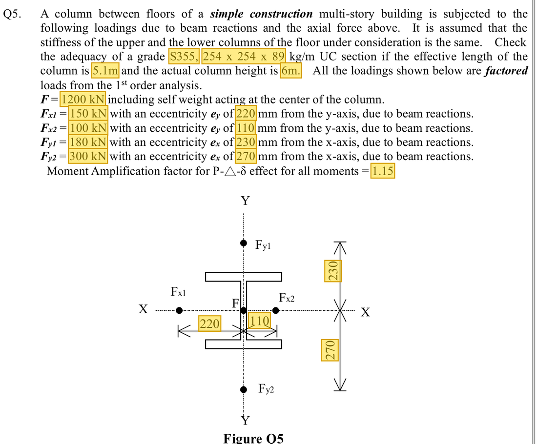
The question in short: A 254×254×89 UC column carries 1200 kN at its centre plus four downward forces that act away from the centre and so bend the column. Find the total compression and the moments about both axes, then check the section and the whole column.
What differs from the previous example of this type: In the previous example the moments were given. Here they come from off-centre forces times their lever arms and are shared equally between the column lengths above and below, and the member checks use no m factors.
| Given | Value and Unit |
|---|---|
| Loading | (at the column centre); Fx1 = 150, Fx2 = 100, Fy1 = 180, Fy2 = 300 kN |
| Lever arms | direction 0.27/0.23 m; direction 0.22/0.11 m |
| Distribution in this problem | Simple construction; the upper and lower columns have the same stiffness, so each takes half the moment; amplification 1.15 about both axes |
| Section | 254×254×89 UC, S355; ; actual column height 6 m |
| Section properties | , ; ; ; , , , |
Yellow: values given in the question. The same values are marked where they are substituted in the steps below.
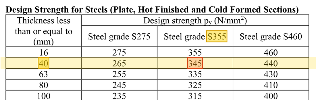
Orange box: values read directly from the Data File, the same values boxed orange in the lookup screenshots. A value interpolated between two table rows is a calculation, so it has no box.


Solution Route: Combine loads→eccentric moments→specified distribution→amplification→section check→two member checks→the lecturer's judgement.
This browser cannot show the 3D model.
The reactions of four beams enter the column at its top. They are off the column centre, so besides axial force they cause moments about both axes; the upper and lower columns each take half of these moments.
- Beam reactions add up to the axial force
- Eccentricity gives moments (half each way), ; amplified to 22.77 and 12.65 kNm
- Cross-section checkSum 0.63Limit 1
- Member check 1 (buckling)Sum 1.05Limit 1marginally OK (as the lecturer reads it)
- Member check 2 (lateral-torsional buckling)Sum 1.052Limit 1marginally OK (as the lecturer reads it)
- Step 1 · Combine axial forces
Why this step: Whether a force acts at the centre or to one side, it all travels down this column, so every force adds to the compression. Acting off-centre only adds a moment as well.
Add all five downward actions, not just the largest 1200.
New symbols in this step- , : Design axial force and buckling compression resistance; kN
- Step 2 · -direction moment
Why this step: A force away from the column centre acts like a spanner and bends the column head. Forces on opposite sides turn it in opposite ways and partly cancel; what is left is the moment at the joint.
Subtract opposing rotations, then divide by 2 for this problem's upper/lower segment distribution.
New symbols in this step- , , : Two-axis and LTB governing moment demands; kNm
- Step 3 · -direction moment
Why this step: The two off-centre forces in the other direction bend the column about its other axis. The moment at the joint is carried by the column lengths above and below; with equal stiffness each takes half.
Again use force times perpendicular lever arm first.
Load path · How the beam reactions bend the columnLeft, the column seen from above. All five forces act downwards and add up to the 1930 kN axial force. Fy1 and Fy2 lie on opposite sides of the axis, so their moments oppose and are subtracted to give the moment about ; Fx1 and Fx2 are subtracted likewise for the moment about . The upper and lower columns are equally stiff and take half each. - Step 4 · Specified amplification
Why this step: Amplifying adds in the extra moment that develops as the compressed column deforms. The moments here are small and stay small after amplification; the column is mainly in compression.
1.15 multiplies moment demand, not section resistance.
- Step 5 · The section can still pass
Why this step: The section check only asks whether the steel is crushed and ignores the length of the column. The low utilisation shows that the weakness of this column is not section strength but the buckling checked next.
The section check uses plastic capacities: for compression and the smaller of and 1.2pyZ for moment.
New symbols in this step- , , : Gross area mm²; yield and compression buckling strengths N/mm²
- , , : Corresponding bending resistances; kNm, with different section/member definitions
Where the numbers come from: from Step 1; from Step 4; from Step 4.
Units: is multiplied by 100 to change cm² into mm²; times gives N, and dividing by 1000 gives kN. and are multiplied by 1000 to change cm³ into mm³; Nmm divided by 1000000 gives kNm, a net division by 1000.
- Step 6 · Buckling reduces resistance
Why this step: The column is fairly slender, so it bows about its weak axis before the steel is crushed, and is much smaller than . The compression term therefore takes up most of the capacity.
; in the column of Table 8.8(c) it lies between the 76 and 78 rows, and interpolation gives .
New symbols in this step- , , , : Effective length and radius of gyration mm; dimensionless slenderness
Units: of 113 cm² is multiplied by 100 to change it into mm². in N/mm² times mm² gives N, and dividing by 1000 gives kN. is mm divided by mm and has no unit.
Data file lookup · Data Page 8 · Table 8.8(c)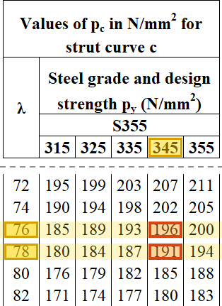
Table 8.8(c), column: → 196 and → 191 N/mm²; interpolating at gives .Yellow: given parameter, row or columnOrange: value read from the table, boxed orange in the text too - Step 7 · First member expression
Why this step: This check asks whether the whole column bows out and buckles under compression plus the eccentric moments. The compression term alone nearly uses up , so adding even small moments takes the total past the limit.
In simple construction the member checks use no m factors and the elastic capacities as denominators. The total is slightly above 1.
Where the numbers come from: from Step 1; from Step 6; from Step 4; from Step 4.
Units: and are multiplied by 1000 to change cm³ into mm³. times mm³ gives Nmm, and dividing by 1000000 gives kNm, so the formula divides by 1000.
- Step 8 · Member LTB expression
Why this step: This check guards against the compression flange moving sideways under the -axis moment, with the column twisting, while the column is in compression. Because the moment is small, using changes the result very little from the first check.
In simple construction with the actual column height, 6 m; interpolate in the column of Table 8.3a and find . With as the denominator of the bending term, the result is still about 1.05.
Where the numbers come from: from Step 1; from Step 6; from Step 4; from Step 4; from Step 7.
Units: The 6 m column height is multiplied by 1000 to give 6000 mm before dividing by in mm. For , is multiplied by 1000 to change cm³ into mm³ and Nmm is divided by 1000000 to give kNm, a net division by 1000.
Data file lookup · Data Page 5 · Table 8.3a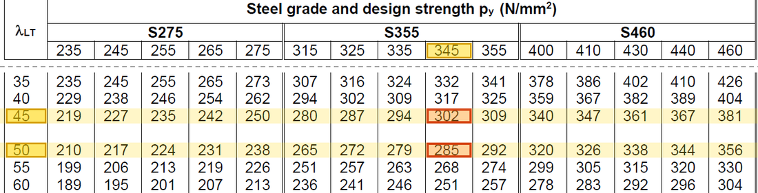
Table 8.3a, column: → 302 and → 285 N/mm²; with the simple-construction , interpolation gives .Yellow: given parameter, row or columnOrange: value read from the table, boxed orange in the text too Load path · How the ratios add upThe cross-section check uses only about 60%. In the member checks the buckling capacity replaces , so the blue axial term grows from 0.495 to 0.893 and the total just passes the red dashed line; the lecturer reads this as marginally OK. - Step 9 · The lecturer's judgement
Why this step: A utilisation of 1 means the capacity is exactly used up; anything above 1 is the share by which demand exceeds capacity. That is why this result is reported with its value, not just as a pass.
Both expressions are about 1.05, only about 5% above 1. The lecturer writes “marginally OK” beside the worksheet, meaning just acceptable. In the exam, follow the lecturer and state which expression it is and its value.
The two member checks give about 1.050 and 1.052, slightly above 1; the lecturer judges this marginally OK (just acceptable). In the answer, write the values and “marginally OK”; do not round to 1 and simply write OK, and do not use the section utilisation 0.63 to offset the member checks. Remark: under the strict ≤1 condition, 1.05 exceeds the limit by about 5%, and the lecturer also says it is, in principle, not OK; in practice a larger section could be used, but all checks must then be repeated.
All the symbols of this example
| Symbols | Meaning and Units |
|---|---|
| , | Design axial force and buckling compression resistance; kN |
| , , | Gross area mm²; yield and compression buckling strengths N/mm² |
| , , , | Effective length and radius of gyration mm; dimensionless slenderness |
| , , | Two-axis and LTB governing moment demands; kNm |
| , , , | Two-axis plastic/elastic moduli; convert the tabulated cm³ |
| , , | Corresponding bending resistances; kNm, with different section/member definitions |
| , , | Total utilisations for the section and two member expressions; dimensionless |
Video positions: 31 October 02:25:00 · 31 October 02:35:00 · 31 October 02:50:00