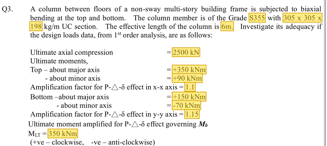
Original question · Lecture notes Chapter 4, p. 40 (Tutorial 4 Q3)
Yellow boxes: values the question gives, the same values marked yellow in the Given table below.
The question in short: A 305×305×198 UC column with an effective length of 6 m carries 2500 kN of compression. End moments are 350 and 150 kNm about the x axis, and 90 and −70 kNm about the y axis. Complete the section check and both member checks.
What differs from the previous example of this type: The section is heavier than in the previous example, and the top and bottom end moments are now given with their signs. So β is found first and mx, my and mLT are looked up, not all taken as 1.
Yellow: values given in the question. The same values are marked where they are substituted in the steps below. Orange box: values read directly from the Data File, the same values boxed orange in the lookup screenshots. A value interpolated between two table rows is a calculation, so it has no box.
Data file lookup · Data Page 11 · Universal Columns — Properties
305×305×198 UC: ry=8.04cm, Zx=2995, Zy=1037, Sx=3440, Sy=1581cm3, u=0.854, x=10.2, A=252cm2.Yellow: given parameter, row or columnOrange: value read from the table, boxed orange in the text too
Data file lookup · Data Page 11 · Universal Columns — Dimensions
305×305×198 UC: flange T=31.4mm.Yellow: given parameter, row or columnOrange: value read from the table, boxed orange in the text too
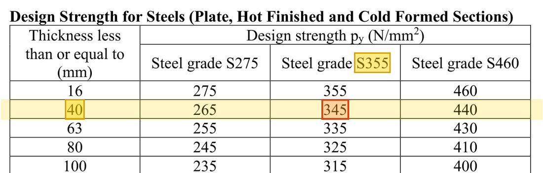
Data file lookup · Data Page 1 · Design strength py
T=31.4mm thick: the T≤40mm row, S355 column gives py=345N/mm2. How the grade and thickness choose this row →Yellow: given parameter, row or columnOrange: value read from the table, boxed orange in the text too
Solution Route: Amplify demand→section resistance/utilisation→λ/pc→β and m factors→first member expression→LTB→second member expression.
Load path · the stations the force passes through, in order
Axial force and end moments about both axes act on the column together. The signs of the end moments fix the m factors, so they change the size of each ratio.
Red frame: the station closest to its limit. Each station links to the step that calculates it.
Step 1 · Amplify demand
Why this step: The end with the larger moment is worked hardest, so it gives the demand. The amplification allows for the extra moment that appears when the compressed column deforms.
Take the larger end-moment magnitude and apply amplification.
New symbols in this step
Mx, My, MLT: Two-axis and LTB governing moment demands; kNm
kx, ky, Mx1, My1: Amplification factors for the two axes; larger end moment before amplification, kNm
Why this step: These are the moments the section itself can carry before it fails in bending, one for each axis. The weak-axis capacity is much smaller, so even a small y-axis moment uses a sizeable share.
For each axis take the smaller of pyS and 1.2pyZ. The latter governs y.
New symbols in this step
Ag, py, pc: Gross area mm²; yield and compression buckling strengths N/mm²
Mcx, Mcy, Mb: Corresponding bending resistances; kNm, with different section/member definitions
Units: S and Z are in cm³ and are multiplied by 1000 to give mm³. py in N/mm² times mm³ gives Nmm, and dividing by 1000000 gives kNm. Together this is a division by 1000.
Why this step: The three terms are the shares of the section's strength used by compression, the x-axis moment and the y-axis moment. A total below 1 means the cross-section at the column end is not crushed.
Agpy=252(100)(345)/1000=8694kN.
New symbols in this step
Fc, Pc: Design axial force and buckling compression resistance; kN
Where the numbers come from: 385 from Step 1; 1186.8 from Step 2; 103.5 from Step 1; 429.3 from Step 2.
Units: Ag of 252 cm² is multiplied by 100 to change it into mm². py in N/mm² times mm² gives N, and dividing by 1000 gives kN.
Step 4 · Buckling strength
Why this step: The column buckles first in its easiest direction, which is about the y axis. So only ry is needed for slenderness; pc is the compressive stress the column can carry before it bows that way.
The y axis is more slender. Use curve c and interpolate between 74 and 76.
New symbols in this step
Le, rx, ry, λ: Effective length and radius of gyration mm; dimensionless slenderness
λ1, λ2, p1, p2: Slenderness and table values of the two rows used for interpolation
Units: The 6 m effective length is multiplied by 1000 to give 6000 mm and divided by ry in mm. Millimetres divided by millimetres leave slenderness with no unit.
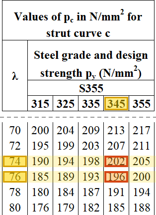
Data file lookup · Data Page 8 · Table 8.8(c)
Table 8.8(c) (y axis, curve c), py=345 column: λ=74 → 202 and λ=76 → 196 N/mm²; interpolating at λ=74.6 gives pc≈200.1N/mm2.Yellow: given parameter, row or columnOrange: value read from the table, boxed orange in the text too
Why this step: Pc is the compression force the whole column can carry before it bows about the weak axis. It is the capacity for the compression term in both member checks.
Units: The area of 252 cm² is multiplied by 100 to change it into mm². pc in N/mm² times mm² gives N, and dividing by 1000 gives kN.
Step 6 · x-axis factors
Why this step: When the end moments bend the column into an S shape, the largest moment occurs only at one end and the middle carries little. This is less harmful for buckling, so mx and mLT are well below 1.
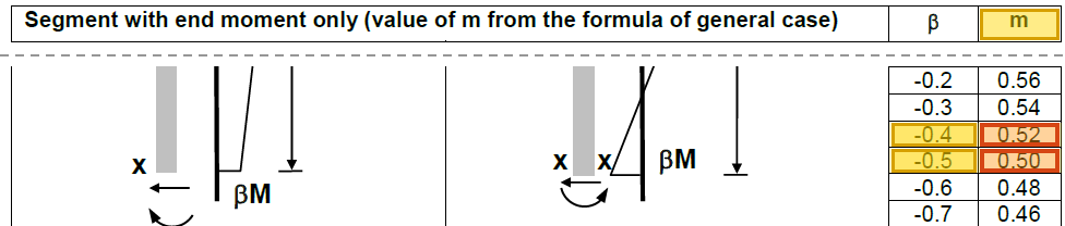
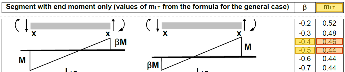
End moments of the same sign (both clockwise) give double curvature, so β is negative; interpolate between the β=−0.4 and −0.5 rows of Tables 8.9 and 8.4a.
Table 8.9: β=−0.4 → 0.52 and β=−0.5 → 0.50; interpolating at βx=−0.429 gives mx≈0.514.Yellow: given parameter, row or columnOrange: value read from the table, boxed orange in the text too
Data file lookup · Data Page 6 · Table 8.4a
Table 8.4a: β=−0.4 → 0.46 and β=−0.5 → 0.44; interpolating at β=−0.429 gives mLT≈0.454.Yellow: given parameter, row or columnOrange: value read from the table, boxed orange in the text too
Step 7 · y-axis factors
Why this step: When the end moments bend the column to the same side, a fairly large moment acts along the whole length, in a shape like the bow of buckling. This is more severe, so my is close to 1.
End moments of opposite sign give single curvature, so β is positive; interpolate between the β=0.7 and 0.8 rows of Table 8.9.
Table 8.9: β=0.7 → 0.88 and β=0.8 → 0.92; interpolating at βy=0.778 gives my≈0.911.Yellow: given parameter, row or columnOrange: value read from the table, boxed orange in the text too
Step 8 · First member expression
Why this step: This check adds the bowing caused by compression to the extra bending from the moments about both axes. The m factors multiply the moments so that only the part that matters for buckling is counted.
Where the numbers come from: 5043 from Step 5; 0.514 from Step 6; 385 from Step 1; 0.911 from Step 7; 103.5 from Step 1.
Units: Zx and Zy are in cm³ and are multiplied by 1000 to give mm³. py times mm³ gives Nmm, and dividing by 1000000 gives kNm, so the formula divides by 1000.
Why this step: The x-axis moment compresses one flange, which can move sideways and twist the column. The factors u and v allow for the section's resistance to twisting and turn the weak-axis slenderness into λLT.
Why this step: pb is the bending stress the column can carry before its flange moves sideways. A stocky UC section does not twist easily, so pb is only a little below py. Mb goes into the second member check.
Units: Sx is in cm³ and is multiplied by 1000 to give mm³. pb in N/mm² times mm³ gives Nmm, and dividing by 1000000 gives kNm. Together this is a division by 1000.
Data file lookup · Data Page 5 · Table 8.3a
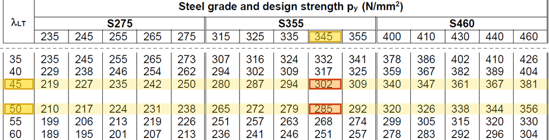
Table 8.3a, py=345 column: λLT=45 → 302 and λLT=50 → 285 N/mm²; interpolating at λLT=46.0 gives pb≈298.5N/mm2.Yellow: given parameter, row or columnOrange: value read from the table, boxed orange in the text too
Step 11 · Second member expression
Why this step: This check asks whether the column, while in compression, moves sideways and twists under the x-axis moment. The x-axis term now uses mLT, MLT and Mb; the other two terms stay the same.
Where the numbers come from: 5043 from Step 5; 0.454 from Step 6; 1026.9 from Step 10; 0.911 from Step 7; 103.5 from Step 1.
Load path · How the ratios add up
Each bar is one check: blue is the share used by the axial force, green and yellow the shares used by the moments about the two axes. Together they must not pass the red dashed line.
Section utilisation 0.853 and member utilisations 0.951/0.914 are all below 1. The column passes. End-moment signs directly affect m factors; retain them when copying the question.
All the symbols of this example
Symbols
Meaning and Units
Fc, Pc
Design axial force and buckling compression resistance; kN
Ag, py, pc
Gross area mm²; yield and compression buckling strengths N/mm²
Le, rx, ry, λ
Effective length and radius of gyration mm; dimensionless slenderness
Mx, My, MLT
Two-axis and LTB governing moment demands; kNm
Sx, Sy, Zx, Zy
Two-axis plastic/elastic moduli; convert the tabulated cm³
Mcx, Mcy, Mb
Corresponding bending resistances; kNm, with different section/member definitions