Example 5: biaxial checks for a non-sway-frame column (Biaxial Column)
Task: Record section and member checks separately and retain signed end moments.
Go straight to Step 1 ↓Design flow for this type of question: Column: axial force with moments →
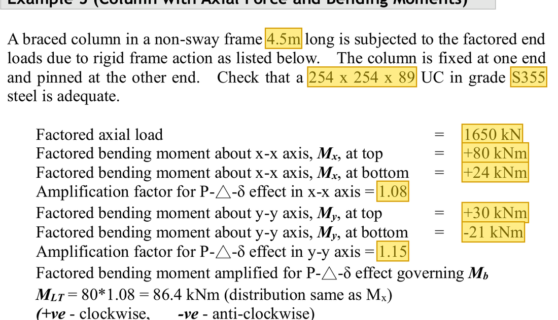
The question in short: A 4.5 m column, 254×254×89 UC, is fixed at one end and pinned at the other. It carries 1650 kN of compression plus end moments about both axes. Decide whether the section is strong enough and whether the whole column buckles.
What differs from the previous example of this type: The previous example had compression only. This one also has moments about both the and axes, so interaction checks add the utilisation from compression and from each moment, with separate section and member checks.
| Given | Value and Unit |
|---|---|
| Column | 4.5 m; fixed at one end, pinned at the other; 254×254×89 UC, S355 |
| Loading | ; end moments +80/+24; end moments +30/−21 kNm |
| Specified amplification | 1.08 about ; 1.15 about |
| Material and section moduli | , ; ; , , , |
| Buckling data | , ; , |
Yellow: values given in the question. The same values are marked where they are substituted in the steps below.
Orange box: values read directly from the Data File, the same values boxed orange in the lookup screenshots. A value interpolated between two table rows is a calculation, so it has no box.


Solution Route: Amplify demand→classification/section capacities→section interaction→effective length /pc→moment factors→member interaction and LTB.
The column carries axial force and end moments about both axes together. The three actions use up the capacity together, so their three ratios are added, in three separate checks with different capacities.
- Axial force and amplified moments; ,
- Cross-section checkSum 0.848Limit 1
- Member check 1 (buckling)Sum 0.949Limit 1closest to the limit
- Member check 2 (lateral-torsional buckling)Sum 0.935Limit 1
- Step 1 · Amplify demand
Why this step: The given factors increase the moments to include the extra bending that appears once the compressed column deforms. For each axis the larger end moment is used, because that end is worked hardest.
Apply the given factors to governing moments; do not add the two end moments.
New symbols in this step- , , : Two-axis and LTB governing moment demands; kNm
- , , , : Amplification factors for the two axes; larger end moment before amplification, kNm
- Step 2 · -axis section resistance
Why this step: is the moment about the strong axis at which the steel across the whole section reaches . It depends only on the section itself, not on the length of the column.
For Class 1/2, plastic resistance is still capped at 1.2 times elastic resistance.
New symbols in this step- , , : Gross area mm²; yield and compression buckling strengths N/mm²
- , , : Corresponding bending resistances; kNm, with different section/member definitions
Units: is in N/mm² and or in cm³. Since 1 cm³ = 1000 mm³, the product is in Nmm after multiplying by 1000. Changing Nmm to kNm divides by 1000000, a net division by 1000.
- Step 3 · -axis section resistance
Why this step: About the weak axis, is much larger than . The upper limit stops the steel from yielding under everyday loads, which would leave a permanent deformation.
The cap governs the weak axis here.
Units: and are in cm³ and are multiplied by 1000 to give mm³. times mm³ gives Nmm, and dividing by 1000000 gives kNm, so the formula divides by 1000.
- Step 4 · Section axial-compression resistance
Why this step: This is the force that would crush the section itself, with all the steel at and no bowing of the column considered. It is the capacity for the compression term in the section interaction check.
Convert area to mm² before multiplying by .
Units: is multiplied by 100 to change cm² into mm². N/mm² times mm² gives N, and dividing by 1000 gives kN.
- Step 5 · Section interaction
Why this step: Compression and the two moments all use the same steel at once. Each term is the share used by one action; if the three add up to no more than 1, the hardest-worked cross-section is not crushed.
Every term is dimensionless; total is about 0.848.
New symbols in this step- , : Design axial force and buckling compression resistance; kN
- , , : Total utilisations for the section and two member expressions; dimensionless
Where the numbers come from: from Step 4; from Step 1; from Step 2; from Step 1; from Step 3.
- Step 6 · Effective length
Why this step: The fixed end stops the column from rotating there, so the part that bows is shorter, like a shorter pin-ended column. A shorter effective length makes buckling less likely.
Fixed at one end and pinned at the other: the effective-length table in the lecture notes gives .
Units: The 4.5 m column height is multiplied by 1000 to give 4500 mm, so is also in mm and can be divided directly by and in mm.
- Step 7 · Two-axis slenderness and curves
Why this step: With the same effective length, the smaller makes the axis more slender and its lower, so the column would bow about the weak axis first. is the force it can carry before that happens.
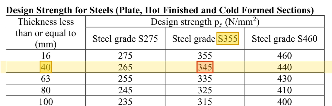
Use curve b (Table 8.8(b)) about and curve c (Table 8.8(c)) about , interpolating each in the column; the smaller value, 246, governs.
New symbols in this step- , , , : Effective length and radius of gyration mm; dimensionless slenderness
Where the numbers come from: from Step 6.
Units: of 113 cm² is multiplied by 100 to change it into mm². in N/mm² times mm² gives N, and dividing by 1000 gives kN. is mm divided by mm and has no unit.
Data file lookup · Data Page 7 · Table 8.7 Buckling curves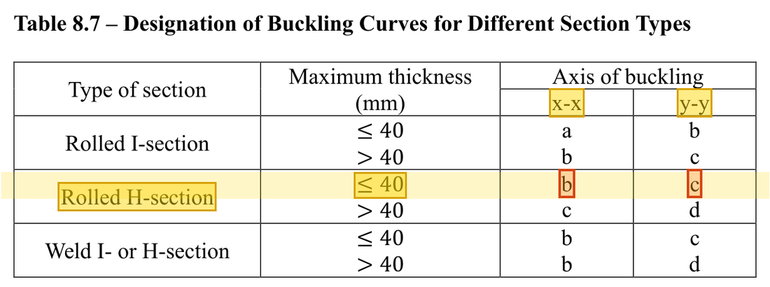
Rolled H-section with thickness ≤ 40 mm: use curve b about the axis and curve c about the axis.Yellow: given parameter, row or columnOrange: value read from the table, boxed orange in the text too Data file lookup · Data Page 8 · Table 8.8(b)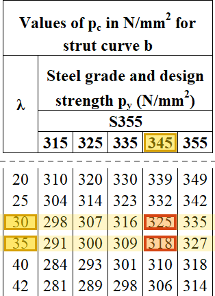
Table 8.8(b) ( axis, curve b), column: → 325 and → 318 N/mm²; interpolating at gives .Yellow: given parameter, row or columnOrange: value read from the table, boxed orange in the text too Data file lookup · Data Page 8 · Table 8.8(c)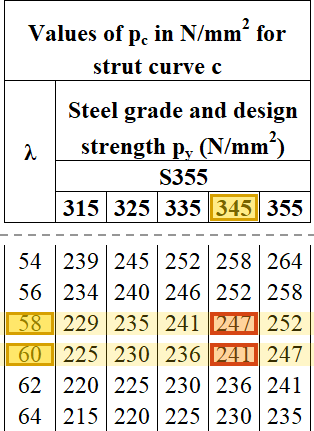
Table 8.8(c) ( axis, curve c), column: → 247 and → 241 N/mm²; interpolating at gives .Yellow: given parameter, row or columnOrange: value read from the table, boxed orange in the text too - Step 8 · Moment-diagram factors
Why this step: The moment changes along the column, so the largest moment does not act over the whole length. When the end moments bend the column into an shape, m is small; when they bend it into a single bow, m is larger.
The course convention gives and , then and . Do not mechanically divide the signed question values.
New symbols in this step- , , : Equivalent moment-distribution factors; dimensionless
Data file lookup · Data Page 7 · Table 8.9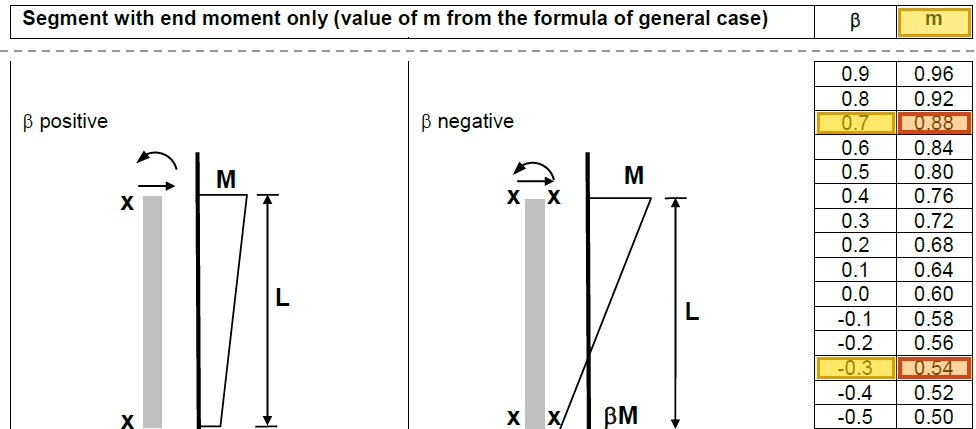
Table 8.9: → ; → .Yellow: given parameter, row or columnOrange: value read from the table, boxed orange in the text too - Step 9 · Elastic capacities for member checks
Why this step: is the moment at which the outermost steel just reaches , a more cautious value than the plastic capacity. It is the denominator when the whole column is checked for buckling.
Use here, not the plastic capacities from the section check.
Units: and are in cm³ and are multiplied by 1000 to give mm³. N/mm² times mm³ gives Nmm, and dividing by 1000000 gives kNm. Together this is a division by 1000.
- Step 10 · First member check
Why this step: This check asks whether the whole column, under compression and both moments together, bows out and buckles. The compression term uses , so it is stricter than the section check.
Recalculation with approximate parameters totals about 0.949.
Where the numbers come from: from Step 7; from Step 1; from Step 9; from Step 1; from Step 9.
- Step 11 · LTB route
Why this step: The moment about the strong axis compresses one flange, which can move sideways and make the column twist. The second member check guards against this by using as the capacity in the -axis term.
From , and find and , interpolate in the column of Table 8.3a, then ; for . The second member check gives about 0.935.
Where the numbers come from: from Step 7; from Step 7; from Step 1; from Step 1; from Step 9.
Units: In , is in cm³ and is multiplied by 1000 to give mm³. N/mm² times mm³ gives Nmm, and dividing by 1000000 gives kNm, so only a division by 1000 remains.
Data file lookup · Data Page 6 · Table 8.4a
Table 8.4a: → .Yellow: given parameter, row or columnOrange: value read from the table, boxed orange in the text too Data file lookup · Data Page 5 · Table 8.3a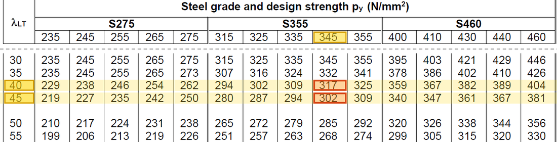
Table 8.3a, column: → 317 and → 302 N/mm²; interpolating at gives .Yellow: given parameter, row or columnOrange: value read from the table, boxed orange in the text too Load path · How the ratios add upEach bar is one check: blue is the share used by the axial force, green and yellow the shares used by the moments about the two axes. Together they must not pass the red dashed line.
With these parameters, the section and both member interactions are below 1. Their different totals reflect different failure modes; do not use the smallest to stand for all checks.
All the symbols of this example
| Symbols | Meaning and Units |
|---|---|
| , | Design axial force and buckling compression resistance; kN |
| , , | Gross area mm²; yield and compression buckling strengths N/mm² |
| , , , | Effective length and radius of gyration mm; dimensionless slenderness |
| , , | Two-axis and LTB governing moment demands; kNm |
| , , , | Two-axis plastic/elastic moduli; convert the tabulated cm³ |
| , , | Corresponding bending resistances; kNm, with different section/member definitions |
| , , | Equivalent moment-distribution factors; dimensionless |
| , , | Total utilisations for the section and two member expressions; dimensionless |
| , , , | Amplification factors for the two axes; larger end moment before amplification, kNm |
Video positions: 31 October 00:25:00 · 31 October 00:30:00 · 31 October 00:35:00 · 31 October 00:40:00