Tutorial 3 Q4: an end couple reverses the bending diagram
Open “Animation lab” beside a teaching step for a visual explanation or a walkthrough of its original expressions. Models are illustrative; source answers remain unchanged.
Need a simpler picture? Open “Simple explanation” beside a difficult step. These optional notes do not replace the full solution.
Check UB S355 against LTB for a design end moment and design point load. Supports A and C are apart; point B is from A and from C. A, B and C have lateral restraints. Normal loads; effective lengths equal actual segment lengths.
Original source: LectureNotes/Ch 3_Beam.pdf — p. 35, p. 36. Values tagged given are in the question or diagram; lookup values come from a named table; calculated values follow from the working; assumptions are stated explicitly.
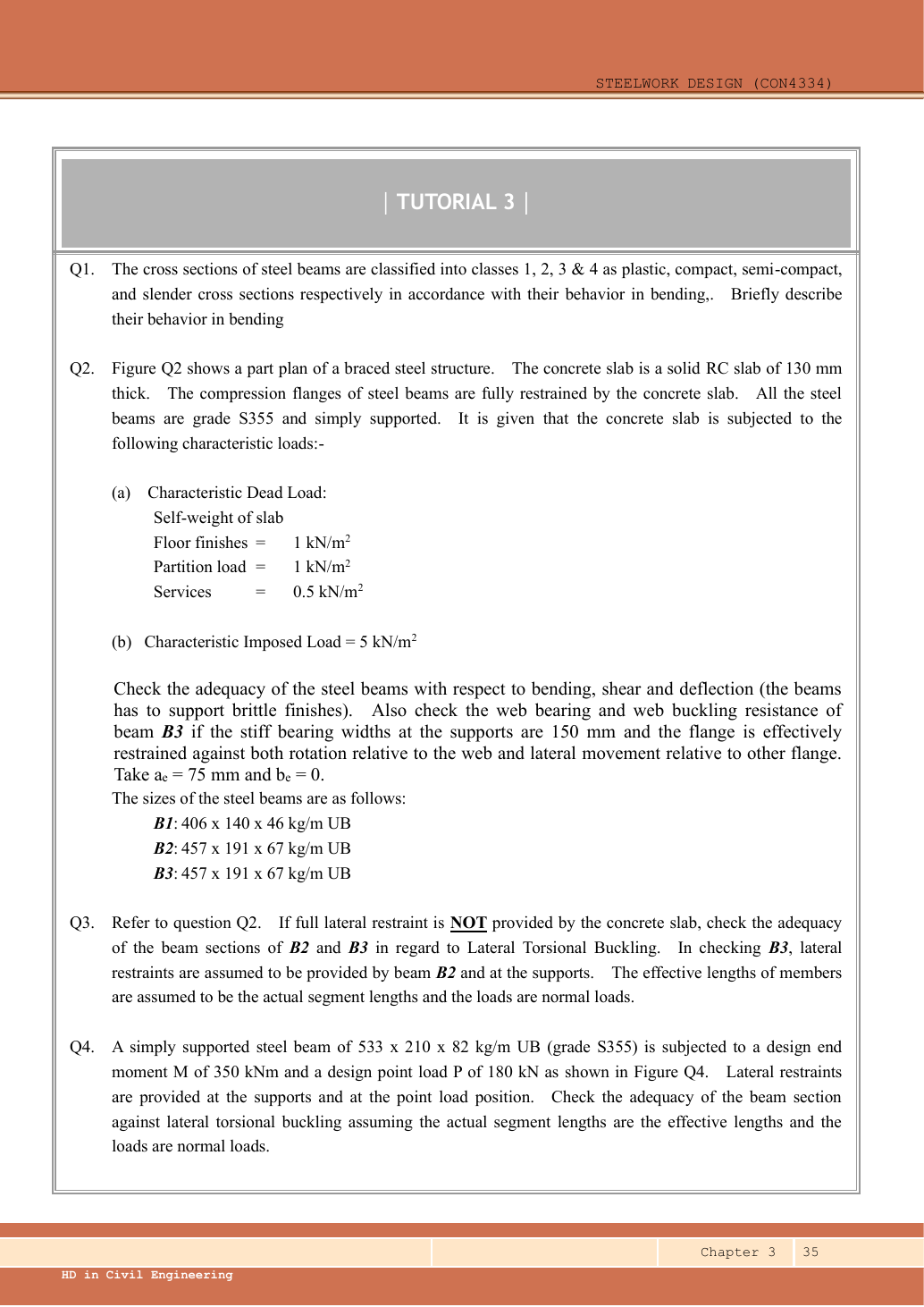
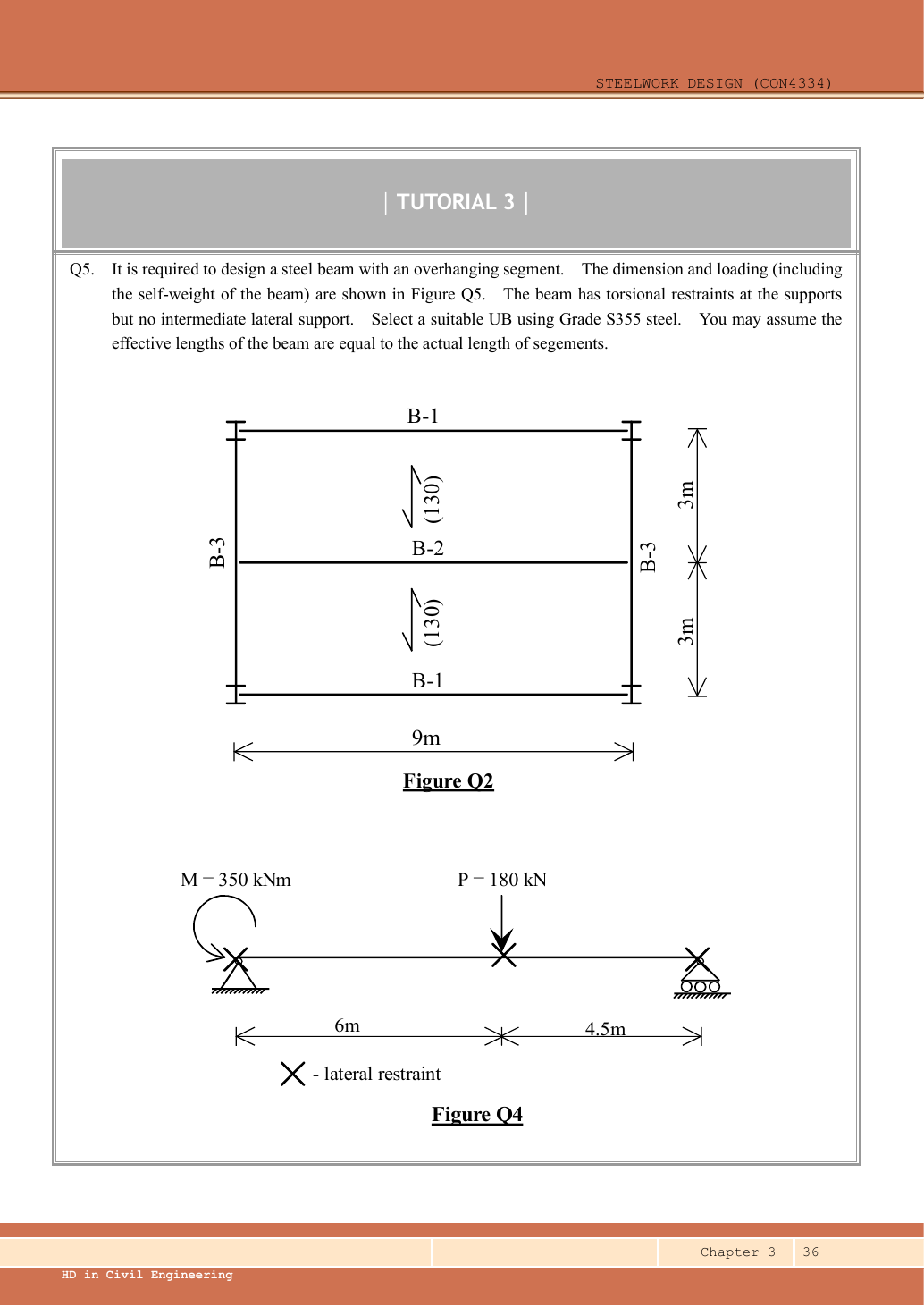
Read the diagram and collect the data
| Input | Given/lookup |
|---|---|
| Loads | Already design values M350 kNm and P180 kN; no / refactoring. |
| Spans | Dimension chain ; B is a load/restraint point, not a support. |
| LTB lengths | AB6,000 mm; BC4,500 mm under the explicit effective-length assumption. |
Lookup: Data File pp.9–10, exact UB row. Dimensions on p.9; properties on p.10. is overall depth; is the clear web depth between root fillets, not the nominal designation.
| Property | Lookup value / conversion |
|---|---|
| Dimensions | D528.3, web t 9.6, flange T13.2, root r 12.7, clear d 476.5, all |
| Local ratios | ;。 |
| Major-axis properties | ; ; . |
| LTB properties | ; ; torsional index . |
Before calculating: recognition and strategy
An applied couple contributes to moment equilibrium but does not add vertical force. It produces a jump in the bending diagram at the end. Find the signed internal end moments for each segment, then use the end-moment LTB factor; the bending diagram is linear between the discrete loads.
1. Find support reactions with the end couple included
Simple explanation: Why reactions balance the loads
Think of a seesaw that must neither fall nor turn.
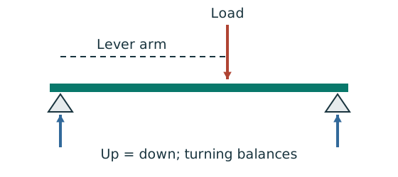
- Upward and downward forces must balance.
- Take moments about a support to eliminate its reaction.
- Use perpendicular distance from the point to the force line.
Remember: A lateral restraint is not automatically a vertical support.
Treating B as a vertical support would create a different statically indeterminate problem. Its× symbol only restrains lateral movement for the stated LTB model.
Animation labBalance reactions and moments
Supplement to the original lesson. Enable JavaScript to play, step through calculations and rotate 3D models. The following explanation remains readable offline.
- This demonstrator is a simply supported 6 m beam with a 60 kN point load; it is not the page’s original loading diagram.
- . Moving the load towards B increases .
- . The two upward reactions must sum to P.
- With the load at midspan, . End couples, UDLs and overhangs require their own equilibrium terms.
2. Construct signed shear and bending ordinates
| Location | Shear immediately right | Bending moment |
|---|---|---|
| (end-couple jump) | ||
Draw horizontal SFD segments at the listed levels, a downward jump at B, and upward at C. Draw straight BMD lines joining at A to at B to at C. The zero crossing at is not a physical lateral restraint.
Animation labBuild the shear and moment diagrams
Supplement to the original lesson. Enable JavaScript to play, step through calculations and rotate 3D models. The following explanation remains readable offline.
- For the illustrative 60 kN point load on a 6 m simply supported beam, balance the reactions before making a cut.
- and before the point load. Moment grows linearly.
- Shear jumps down by P. To its right, and .
- For this case, moment is continuous and returns to zero at B. A concentrated applied couple instead creates a moment jump.
3. Check the AB segment
Simple explanation: A beam can escape sideways
The compressed flange can move sideways while the section twists.
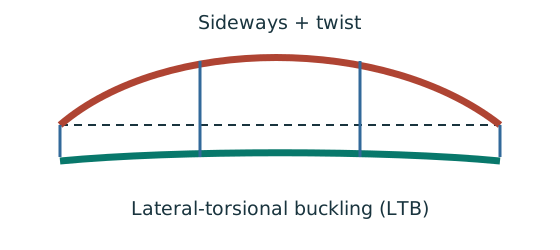
- Divide the beam at effective lateral restraints.
- Use each segment’s effective length to obtain its buckling resistance.
- Compare that resistance with the segment’s equivalent moment demand.
Remember: A section bending check alone does not check lateral-torsional buckling.
AB has reversing moment: maximum magnitude occurs at A. The smaller signed end ordinate is opposite to, so the ratio is negative.
Normal-load effective length is the given segment length. All quantities in and λᴸᵀ are dimensionless. This Class 1 section has .
Table 8.3a, Data File p.5, pᵧ355 column:
Animation labA beam bends sideways and twists
Supplement to the original lesson. Enable JavaScript to play, step through calculations and rotate 3D models. The following explanation remains readable offline.
- For the illustrated sagging beam the top flange is compressed.
- The unrestrained compression flange can move sideways while the complete cross-section twists.
- Only effective restraints divide the member into unbraced segments. They do not automatically add vertical supports.
- Use the segment effective length, section properties and matching moment factor. This is an exaggerated mode shape, not a calculated displacement.
4. Check the BC segment and conclude
Simple explanation: Which length belongs in the calculation?
A sideways tie can shorten the buckling region without shortening the beam’s vertical span.
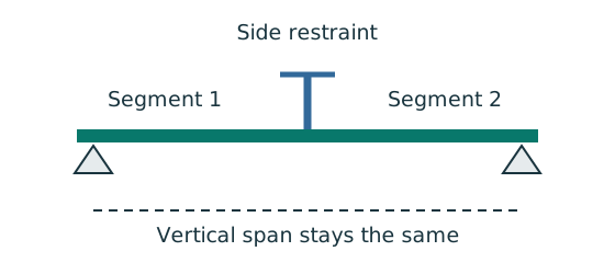
- Separate vertical-support spacing from lateral-restraint spacing.
- Apply the course rule for the actual end restraint and loading.
- Keep the original vertical load analysis unless its supports change.
Remember: Restraints in one direction may not restrain the other direction.
Normal-load effective length is the given segment length. All quantities in and λᴸᵀ are dimensionless. This Class 1 section has .
Table 8.3a, Data File p.5, pᵧ355 column:
Both required segment LTB checks pass. As a scope check, the peak shear and largest moment magnitude also satisfy the local section checks:
A numerical support bearing check or imposed-load deflection cannot be derived from this source because bearing dimensions and characteristic load components are not supplied. They are not part of Q4’s stated LTB-only request.
Animation labA beam bends sideways and twists
Supplement to the original lesson. Enable JavaScript to play, step through calculations and rotate 3D models. The following explanation remains readable offline.
- For the illustrated sagging beam the top flange is compressed.
- The unrestrained compression flange can move sideways while the complete cross-section twists.
- Only effective restraints divide the member into unbraced segments. They do not automatically add vertical supports.
- Use the segment effective length, section properties and matching moment factor. This is an exaggerated mode shape, not a calculated displacement.
Compact exam answer
, . , , . AB: , , ; demand . BC: , , ; demand . S355 UB passes LTB in both segments.
Mistakes to avoid
- Do not factor already-design loads again.
- Do not omit the couple in support equilibrium.
- Do not use absolute-value end moments to form a same-side when the BMD reverses.
- Do not insert a restraint at the moment-zero point.
Procedure for an unfamiliar variant
- Name supports and load positions using the source dimension chains.
- Choose a sign convention; include applied couples in moment equilibrium.
- Find reactions, then piecewise shear and bending moment.
- Locate extrema where shear is zero and at load/support discontinuities.
- Divide only at actual effective lateral restraints; classify and read the exact section row.
- Calculate segment moment factors and LTB resistance, retaining UDL curvature where present.
- Check shear, local bending and serviceability; state any missing bearing/detail inputs.
Independent self-check
Try it yourself. Invented variant: remove the lateral restraint at B but keep the same vertical loads. Can the two segment pass results still be used?
Reveal answer and reasoning
No. The unrestrained length becomes . Recalculate the whole-span quarter-point BMD factor and with . The vertical reactions and BMD are unchanged; the stability resistance changes because B is no longer a restraint.