Tutorial 3 Q5: design a beam with a overhang
Open “Animation lab” beside a teaching step for a visual explanation or a walkthrough of its original expressions. Models are illustrative; source answers remain unchanged.
Need a simpler picture? Open “Simple explanation” beside a difficult step. These optional notes do not replace the full solution.
Select a suitable S355 UB for the source beam: supports at and , free end at ; characteristic point loads at and , each dead and imposed ; full-length UDL dead and imposed , including beam self-weight. Supports provide torsional restraint, no intermediate lateral support, and effective lengths equal actual segment lengths.
Original source: LectureNotes/Ch 3_Beam.pdf — p. 36, p. 37. Values tagged given are in the question or diagram; lookup values come from a named table; calculated values follow from the working; assumptions are stated explicitly.
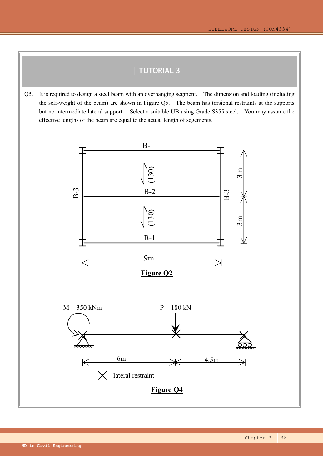
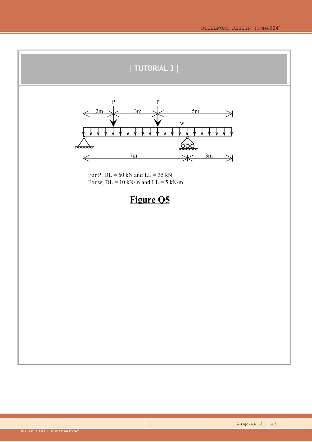
Read the diagram and collect the data
| Input | Origin/type |
|---|---|
| Characteristic point loads | Given eachP: dead , imposed ; two points total. |
| Characteristic UDL | Given dead , imposed over ; self-weight included, so do not add the selected mass again. |
| LTB lengths | Given actual segment lengths: main span ; overhang . |
| Selected result | UB is a checked trial from the supplied Data File; it is not claimed to be the globally lightest possible design. |
Before calculating: recognition and strategy
First solve the full free body; using for this overhanging beam would be wrong. Peak sagging lies between the two point loads where shear crosses zero; the roller also has hogging moment. After deriving the LTB demand, test a plausible section and reject it if necessary. For the overhang use conservative ; do not apply a simply supported triangular-moment shortcut to a free end.
1. Factor the actual loads once
Simple explanation: Why dead and imposed loads stay separate
Keep two shopping baskets until their different multipliers are applied.
- Put self-weight and permanent finishes in the dead-load basket.
- Put the specified use load in the imposed-load basket.
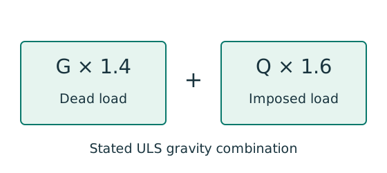
- For this course’s stated gravity combination: .
Remember: That ULS combination is not the imposed-load deflection load.
Self-weight is already included in dead . All subsequent strength results use these ultimate loads. The serviceability calculation later returns to imposed and .
Animation labSee stiffness and deflection
Supplement to the original lesson. Enable JavaScript to play, step through calculations and rotate 3D models. The following explanation remains readable offline.
- Use the specified SLS load, span and support arrangement. The demonstrator has a full-span UDL.
- The loaded beam bends; the deformation is exaggerated so its shape can be seen.
- For a simply supported full-span UDL, . Double L with w, E and I unchanged: δ becomes 16 times as large.
- The readout uses , and . Select the finish/support-specific limit from the original table.
2. Reactions, shear and bending over the full beam
| Interval | Shear equation () | End shear levels |
|---|---|---|
Support reaction is local bearing demand, not the beam's maximum internal shear. The shear diagram has four sloping straight segments, with jumps , , . The moment diagram is piecewise parabolic, continuous at point loads, with the above peak and the roller moment .
Animation labBalance reactions and moments
Supplement to the original lesson. Enable JavaScript to play, step through calculations and rotate 3D models. The following explanation remains readable offline.
- This demonstrator is a simply supported 6 m beam with a 60 kN point load; it is not the page’s original loading diagram.
- . Moving the load towards B increases .
- . The two upward reactions must sum to P.
- With the load at midspan, . End couples, UDLs and overhangs require their own equilibrium terms.
3. Obtain LTB demand and reject an insufficient trial
There is no lateral restraint at either point load. The main span is one LTB segment. Its local quarter positions are , and , and the maximum magnitude in that segment is .
Try UB. Its large plastic moment capacity is not enough evidence; compute its LTB resistance.
Lookup: Data File pp.9–10, exact UB row. Dimensions on p.9; properties on p.10. is overall depth; is the clear web depth between root fillets, not the nominal designation.
| Property | Lookup value / conversion |
|---|---|
| Dimensions | D539.5, web t 11.6, flange T18.8, root r 12.7, clear d 476.5, all |
| Local ratios | ;。 |
| Major-axis properties | ; ; . |
| LTB properties | ; ; torsional index . |
Normal-load effective length is the given segment length. All quantities in and λᴸᵀ are dimensionless. This Class 1 section has .
Table 8.3a, Data File p.5, pᵧ345 column:
The trial fails:. Choose the next heavier row in this depth series, UB, and re-read all its properties; do not reuse the109 kg/m thickness or radius.
Lookup: Data File pp.9–10, exact UB row. Dimensions on p.9; properties on p.10. is overall depth; is the clear web depth between root fillets, not the nominal designation.
| Property | Lookup value / conversion |
|---|---|
| Dimensions | D544.5, web t 12.7, flange T21.3, root r 12.7, clear d 476.5, all |
| Local ratios | ;。 |
| Major-axis properties | ; ; . |
| LTB properties | ; ; torsional index . |
Animation labA beam bends sideways and twists
Supplement to the original lesson. Enable JavaScript to play, step through calculations and rotate 3D models. The following explanation remains readable offline.
- For the illustrated sagging beam the top flange is compressed.
- The unrestrained compression flange can move sideways while the complete cross-section twists.
- Only effective restraints divide the member into unbraced segments. They do not automatically add vertical supports.
- Use the segment effective length, section properties and matching moment factor. This is an exaggerated mode shape, not a calculated displacement.
4. Check both segments of the selected UB
Simple explanation: Why the shape of the moment diagram matters
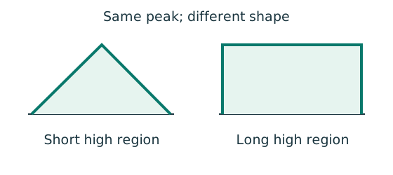
The same peak moment is more demanding when a long region stays near that peak.
- Use the diagram of this unrestrained segment.
- Choose the applicable course sketch or quarter-point rule.
- Apply its factor to the demand, following the stated check.
Remember: Column flexural-buckling factors and LTB factors are not interchangeable.
Main span: use the same load-derived demand but the new section properties.
Normal-load effective length is the given segment length. All quantities in and λᴸᵀ are dimensionless. This Class 1 section has .
Table 8.3a, Data File p.5, pᵧ345 column:
Overhang : its maximum hogging magnitude is at B. Use conservative , hence demand . The problem expressly permits effective length equal to the actual ; do not silently impose a different cantilever factor.
Normal-load effective length is the given segment length. All quantities in and λᴸᵀ are dimensionless. This Class 1 section has .
Table 8.3a, Data File p.5, pᵧ345 column:
Both selected-section LTB checks pass. Restraint at B must be effective for the specified hogging/compression-flange condition; the question grants the torsional restraint model.
Animation labA beam bends sideways and twists
Supplement to the original lesson. Enable JavaScript to play, step through calculations and rotate 3D models. The following explanation remains readable offline.
- For the illustrated sagging beam the top flange is compressed.
- The unrestrained compression flange can move sideways while the complete cross-section twists.
- Only effective restraints divide the member into unbraced segments. They do not automatically add vertical supports.
- Use the segment effective length, section properties and matching moment factor. This is an exaggerated mode shape, not a calculated displacement.
5. Local strength, imposed-load deflection and remaining scope
Simple explanation: How much does the beam sag?
Strength asks whether it fails; deflection asks how far it moves.
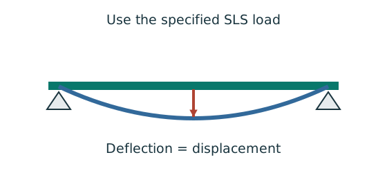
- Use the serviceability load case specified by the course question.
- Choose the expression matching the support and load positions.
- Use consistent units for load, length, E and I.
Remember: The largest deflection is not always at midspan.
Serviceability uses each imposed point load , . Treat the whole beam as a continuous elastic member passing over two simple supports. A fixed-cantilever formula would omit rotation of the section at the roller.
Take downward deflection positive, in . Integrating twice gives the following expression. The support atx 0 forces the constant displacement term to zero; determines the remaining constant .
Differentiate once and set slope to zero in each interval. The only internal stationary deflection along the beam is in , where only the first point-load bracket is active:
The source does not specify finishes. Demonstrating the stricter span limit avoids inventing a finish type. Loading on the main span rotates the support section, so the free end can move upwards. This calculation covers the simultaneous load pattern drawn; it does not claim an envelope from separate imposed-load patterns.
Animation labSee shear in the web
Supplement to the original lesson. Enable JavaScript to play, step through calculations and rotate 3D models. The following explanation remains readable offline.
- Internal shear keeps the two sides of the cut in vertical equilibrium.
- For the course’s common I-section case, the web provides the principal shear area; use the specified definition.
- A slender web may require a different shear-buckling route before a simple shear-resistance formula is used.
- Use where applicable in the course. Convert N to kN before comparing with design shear.
Compact exam answer
P140 kN,w 22 kN/m; RA202.857143,RB297.142857 kN. Peak internal shear ; saggingM369.795918 kNm atx 2.857143 m, hogging−99 atB. Main-span LTB demand . Trial fails(Mb 340.735220); select : mainMb 410.186820, overhangMb 877.593606 kNm with conservative overhangmLT1. ShearVc 1377.400 kN and Mc 1102.620 kNm pass. Imposed deflection downward in span and upward at tip. Bearing/local-web detail checks remain incomplete because source inputs are absent.
Mistakes to avoid
- Do not read the upper dimension as distance to the roller.
- Do not add self-weight again.
- Do not use the support reaction as the maximum beam internal shear.
- Do not split LTB length at an unrestrained point load.
- Do not use a fixed-cantilever deflection formula for a rotating support.
Procedure for an unfamiliar variant
- Name supports and load positions using the source dimension chains.
- Choose a sign convention; include applied couples in moment equilibrium.
- Find reactions, then piecewise shear and bending moment.
- Locate extrema where shear is zero and at load/support discontinuities.
- Divide only at actual effective lateral restraints; classify and read the exact section row.
- Calculate segment moment factors and LTB resistance, retaining UDL curvature where present.
- Check shear, local bending and serviceability; state any missing bearing/detail inputs.
Independent self-check
Try it yourself. Invented variant: can the rejected section be accepted by rounding its resistance to ?
Reveal answer and reasoning
No. The demand exceeds the unrounded resistance by , a utilisation of about . Rounding must not change a failed limit-state check into a pass. Change the section or restraint arrangement and recalculate.