Assignment 1 Q1: storage-floor beams and an annotated connection sketch
Open “Animation lab” beside a teaching step for a visual explanation or a walkthrough of its original expressions. Models are illustrative; source answers remain unchanged.
Need a simpler picture? Open “Simple explanation” beside a difficult step. These optional notes do not replace the full solution.
For the source storage-floor plan, find ultimate slab intensity, B1 and B2 maximum shear/moment, both section classes, and B2 shear/bending/deflection adequacy. Then produce the requested annotated isometric slab–B1–B2 web-weld connection sketch. S355 beams are simply supported and fully laterally restrained by concrete slabs, with brittle finishes.
Original source: Assignment/AY2627s 1-CON4334-Assignment 1.pdf — p. 1. Values tagged given are in the question or diagram; lookup values come from a named table; calculated values follow from the working; assumptions are stated explicitly.
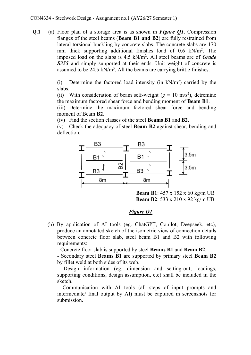
Read the diagram and collect the data
| Input | Exact origin |
|---|---|
| Slab | Given thickness ; unit weight ; additional finish ; imposed . |
| Gravity | The question explicitly specifies the beam self-weight calculation using ; use this value rather than another default. |
| Given UB; Data File p.9 mass (nominal designation ). | |
| Given UB; Data File p.9 mass (nominal designation ). | |
| Restraints/finish | Given simple supports, full slab compression-flange lateral restraint and brittle finish. LTB is suppressed in this particular check. |
| Connection sketch | Part(b) explicitly calls for secondary B1 supported by primary B2 with fillet welds at both sides of B1’s web; no weld leg, length, cope size or connection plate detail is specified. |
Before calculating: recognition and strategy
Start at the slab, convert surface intensity to B1 line load using tributary width, and pass both B1 reactions into the middle of B2. End-joint reactions from B3 occur at B2’s vertical supports and do not create additional B2 span bending in the simple model. Strength and deflection use different load combinations.
(a)(i) Ultimate slab load intensity
Simple explanation: Why dead and imposed loads stay separate
Keep two shopping baskets until their different multipliers are applied.
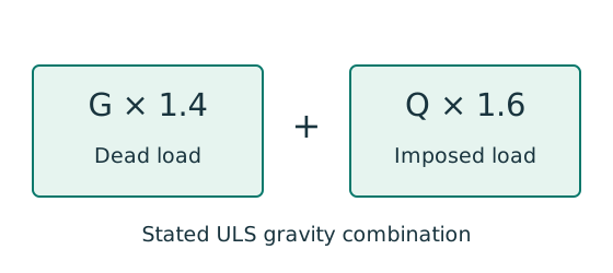
- Put self-weight and permanent finishes in the dead-load basket.
- Put the specified use load in the imposed-load basket.
- For this course’s stated gravity combination: .
Remember: That ULS combination is not the imposed-load deflection load.
The extra finish is dead load; “brittle” controls the later deflection limit and does not change its load category.
Animation labFrom characteristic to design load
Supplement to the original lesson. Enable JavaScript to play, step through calculations and rotate 3D models. The following explanation remains readable offline.
- G is permanent load; Q is imposed load. A surface load and a line load also have different units.
- This illustration uses the course gravity case . Other combinations in the original text retain their own factors.
- For illustrative , change Q and watch each separate contribution.
- Do not carry this ULS total automatically into deflection. Follow the stated SLS load case.
(a)(ii) B1 maximum factored shear and moment
One B1’s full factored load is , but its reaction on B2 is half of that,. The numerical equality between this full load in and its maximum moment in is coincidental for ; the quantities and units remain different.
Animation labFollow the floor load in 3D
Supplement to the original lesson. Enable JavaScript to play, step through calculations and rotate 3D models. The following explanation remains readable offline.
- The floor carries pressure in . The highlighted strip belongs to one secondary beam.
- Multiply pressure by tributary width: . The illustration uses .
- A primary beam receives the secondary beam reaction at their connection, not a new full-span UDL.
- Trace reactions down to columns and foundations. Count each loaded area once.
(a)(iii) B2 maximum factored shear and moment
Simple explanation: How a floor load reaches a beam
Each beam collects the load from its own strip of floor.
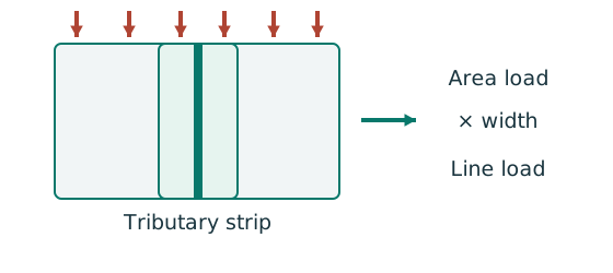
- Find the tributary width from the actual plan.
- Area load × tributary width gives load per beam length.
- A supporting beam receives the other beam’s end reaction.
Remember: A reaction becomes a point load, not automatically a UDL.
Do not apply / to again: it is already assembled from ultimate B1 reactions. Only B2’s newly introduced self-weight is factored at this step.
Animation labFollow the floor load in 3D
Supplement to the original lesson. Enable JavaScript to play, step through calculations and rotate 3D models. The following explanation remains readable offline.
- The floor carries pressure in . The highlighted strip belongs to one secondary beam.
- Multiply pressure by tributary width: . The illustration uses .
- A primary beam receives the secondary beam reaction at their connection, not a new full-span UDL.
- Trace reactions down to columns and foundations. Count each loaded area once.
(a)(iv) Both section classes
Simple explanation: A thin part can wrinkle first
A thin plate may wrinkle before the whole steel member reaches its intended resistance.
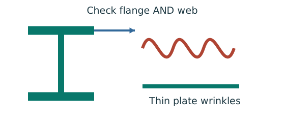
- Check flange and web slenderness using their own definitions.
- Compare each ratio with the correct class limits.
- The less favourable element determines the section class.
Remember: Bending limits and uniform-compression limits are different.
Read each exact UB row; the weakest compression element governs. Pure bending has a web compression/tension stress gradient, so use the bending web limit for Class 1, not the uniform-compression column limit.
Lookup: Data File pp.9–10, exact UB row. Dimensions on p.9; properties on p.10. is overall depth; is the clear web depth between root fillets, not the nominal designation.
| Property | Lookup value / conversion |
|---|---|
| Dimensions | D454.6, web t 8.1, flange T13.3, root r 10.2, clear d 407.6, all |
| Local ratios | ;。 |
| Major-axis properties | ; ; . |
| LTB properties | ; ; torsional index . |
Lookup: Data File pp.9–10, exact UB row. Dimensions on p.9; properties on p.10. is overall depth; is the clear web depth between root fillets, not the nominal designation.
| Property | Lookup value / conversion |
|---|---|
| Dimensions | D533.1, web t 10.1, flange T15.6, root r 12.7, clear d 476.5, all |
| Local ratios | ;。 |
| Major-axis properties | ; ; . |
| LTB properties | ; ; torsional index . |
Both sections are Class 1, and both flange thicknesses lie in the range, so use . Both web ratios are also below , so the course trigger does not require a separate shear-buckling check.
Animation labWhy thin elements buckle locally
Supplement to the original lesson. Enable JavaScript to play, step through calculations and rotate 3D models. The following explanation remains readable offline.
- The flange outstand and web have different widths, thicknesses and edge support conditions.
- A thinner plate can wrinkle locally before the complete member loses stability.
- Class 1 allows plastic rotation; Class 2 reaches plastic resistance; Class 3 reaches elastic resistance; Class 4 requires effective properties.
- Check every relevant compression element with the supplied limits and stress distribution. The deformation shown is qualitative.
(a)(v) B2 strength and brittle-finish deflection
Simple explanation: How much does the beam sag?
Strength asks whether it fails; deflection asks how far it moves.
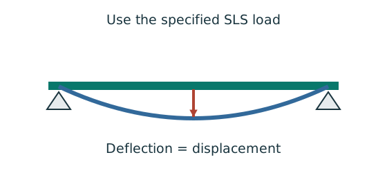
- Use the serviceability load case specified by the course question.
- Choose the expression matching the support and load positions.
- Use consistent units for load, length, E and I.
Remember: The largest deflection is not always at midspan.
The slab fully restrains the compression flange by the question’s explicit assumption, so use the cross-section bending resistance. Do not claim that this assumption proves the weld detail in(b) supplies a rigid moment connection.
B2 is adequate for the requested shear, bending and imposed-load deflection checks. This part does not supply the contact dimensions needed for separate support web-bearing detail checks.
Animation labSee shear in the web
Supplement to the original lesson. Enable JavaScript to play, step through calculations and rotate 3D models. The following explanation remains readable offline.
- Internal shear keeps the two sides of the cut in vertical equilibrium.
- For the course’s common I-section case, the web provides the principal shear area; use the specified definition.
- A slender web may require a different shear-buckling route before a simple shear-resistance formula is used.
- Use where applicable in the course. Convert N to kN before comparing with design shear.
(b) Completed annotated isometric teaching sketch
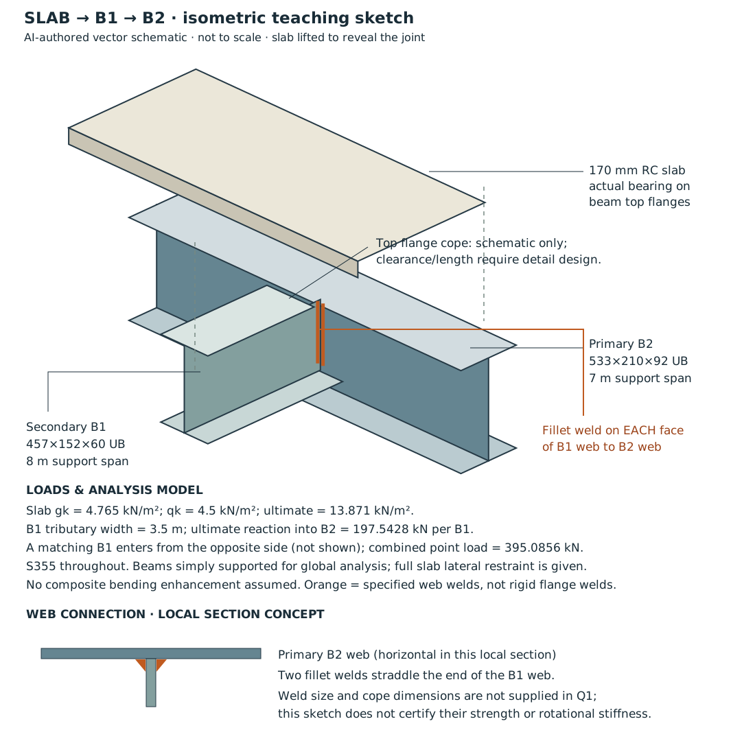
Selectable equivalents of the diagram labels and formulas: slab thickness ; primary beam B2 is UB, with a support-to-support span of ; secondary beam B1 is UB, with a support-to-support span of . For the slab, , , with ultimate load . The tributary width of B1 is ; each B1 delivers an ultimate reaction to B2 of . Together with the B1 on the opposite side, which is not drawn, the total point load is . All steel is S355. The simply supported overall model and the fully restrained condition given in the question are unchanged; no increase in bending resistance from composite action is assumed. These are selectable equivalents of values already labelled in the drawing, not additional question data.
The drawing shows the requested slab, primary B2 and a perpendicular secondary B1. A matching B1 meets the far side in the floor plan; it is identified in the annotations to keep the joint visible. Orange marks the two fillets on the faces of B1’s web. The slab is lifted only for visibility; in the actual assembly it bears on the beam top flanges. A conceptual top-flange cope is identified to avoid drawing solid steel members unrealistically through each other.
The simple-support global model requires appropriate rotational behaviour in the actual connection. Welding both web faces does not, by itself, establish a rigid beam-end moment connection. The sketch deliberately makes no unsupported weld-size or cope-dimension claim. Those are connection-design inputs not provided in Q1; the supplied beam sizes, spans, slab depth, loads and assumptions are fully annotated.
AI-process evidence required by the assignment: the SVG above is an actual AI-authored output for this learning website. It is not a historical screenshot record of a student’s conversation. For an assessed submission, capture your own complete prompt/output sequence, including revisions; do not fabricate screenshots or present suggested prompts as past interactions.
| An illustrative prompt sequence for learning | What to verify in the resulting output |
|---|---|
| “Create an isometric schematic from this exact floor plan: slab; B1 spanning into B2 spanning ; two fillet welds on the B1 web; include only the provided dimensions.” | Correct beam orientation, both web welds, real slab support and no invented weld leg. |
| “Add the independently checked loads: , ; reaction from each B1 , combining at B2 midspan to give . Identify the exploded slab display and any conceptual cope.” | Units, centroid/load positions and given-versus-assumed labels match the calculation. |
| “Audit the sketch for crossed solid flanges, absent welds, unsupported connection dimensions and an unjustified rigid-joint claim; revise and list changes.” | Keep both the flawed intermediate image and the corrected output in your genuine evidence trail. |
These prompts are clearly labelled illustrations, not a fabricated transcript. The completed vector can be opened locally and printed without online services. The assignment’s student-specific screenshot trail remains separate evidence that this source package cannot supply.
Animation labFollow the floor load in 3D
Supplement to the original lesson. Enable JavaScript to play, step through calculations and rotate 3D models. The following explanation remains readable offline.
- The floor carries pressure in . The highlighted strip belongs to one secondary beam.
- Multiply pressure by tributary width: . The illustration uses .
- A primary beam receives the secondary beam reaction at their connection, not a new full-span UDL.
- Trace reactions down to columns and foundations. Count each loaded area once.
Compact exam answer
(a) Ultimate area load . B1: , , . B2: plus uniformly distributed load ,, . Both are Class 1, . B2 passes shear and low-shear bending; imposed-load deflection . (b) An annotated local isometric SVG is provided. Connection dimensions absent from the source and a student-specific screenshot history have not been invented.
Mistakes to avoid
- Do not use as B2’s span.
- Do not send one B1’s full load as its end reaction.
- Do not double-factor B1 reactions on B2.
- Do not use in the imposed-only deflection.
- Do not fabricate AI-process screenshot evidence.
Procedure for an unfamiliar variant
- Read slab span direction and tributary width.
- Calculate characteristic surface loads, then factored intensity.
- Include each beam’s self-weight once.
- Transfer reactions through the floor hierarchy.
- Classify and run the requested strength/serviceability checks.
- Annotate the sketch with verified values and clearly identify conceptual details.
Independent self-check
Try it yourself. Invented variant: only one of the two B1 beams meets B2 at midspan, with all other values unchanged. Find B2 maximum moment and imposed deflection.
Reveal answer and reasoning
Central becomes . B2 moment: Central imposed load halves to , giving B2 self-weight is unchanged, so the total moment used for the strength check does not halve exactly.
Animation labBalance reactions and moments
Supplement to the original lesson. Enable JavaScript to play, step through calculations and rotate 3D models. The following explanation remains readable offline.
- This demonstrator is a simply supported 6 m beam with a 60 kN point load; it is not the page’s original loading diagram.
- . Moving the load towards B increases .
- . The two upward reactions must sum to P.
- With the load at midspan, . End couples, UDLs and overhangs require their own equilibrium terms.