Assignment 2 Q2: an intermediate restraint at an off-centre load
Open “Animation lab” beside a teaching step for a visual explanation or a walkthrough of its original expressions. Models are illustrative; source answers remain unchanged.
Need a simpler picture? Open “Simple explanation” beside a difficult step. These optional notes do not replace the full solution.
For UB S355, assumed Class 1, find support reactions and draw annotated SFD/BMD under ultimateP60 kN at from A plus full-span UDL over . Check segmentAB LTB using accurateu andv, and discuss removing restraintB.
Original source: Assignment/AY2627s 1-CON4334-Assignment 2.pdf — p. 2. Values tagged given are in the question or diagram; lookup values come from a named table; calculated values follow from the working; assumptions are stated explicitly.
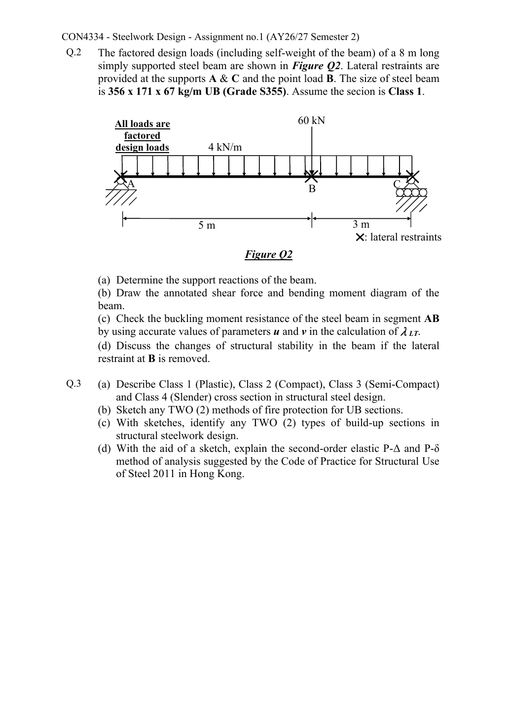
Read the diagram and collect the data
Lookup: Data File pp.9–10, exact UB row. Dimensions on p.9; properties on p.10. is overall depth; is the clear web depth between root fillets, not the nominal designation.
| Property | Lookup value / conversion |
|---|---|
| Dimensions | D363.4, web t 9.1, flange T15.7, root r 10.2, clear d 311.6, all |
| Local ratios | ;。 |
| Major-axis properties | ; ; . |
| LTB properties | ; ; torsional index . |
Before calculating: recognition and strategy
Vertical equilibrium gives one simply supported beam. Lateral stability is assessed over shorter segments. Keep these two models distinct: is the AB stability length, not a simply supported vertical-load span.
(a) Support reactions
Simple explanation: Why reactions balance the loads
Think of a seesaw that must neither fall nor turn.
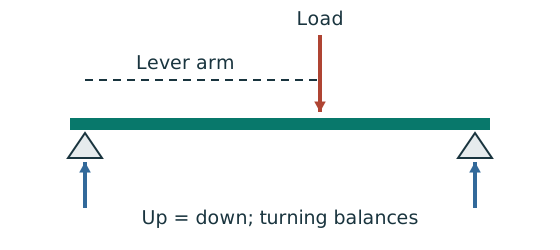
- Upward and downward forces must balance.
- Take moments about a support to eliminate its reaction.
- Use perpendicular distance from the point to the force line.
Remember: A lateral restraint is not automatically a vertical support.
Animation labBalance reactions and moments
Supplement to the original lesson. Enable JavaScript to play, step through calculations and rotate 3D models. The following explanation remains readable offline.
- This demonstrator is a simply supported 6 m beam with a 60 kN point load; it is not the page’s original loading diagram.
- . Moving the load towards B increases .
- . The two upward reactions must sum to P.
- With the load at midspan, . End couples, UDLs and overhangs require their own equilibrium terms.
(b) Annotated shear and bending diagrams
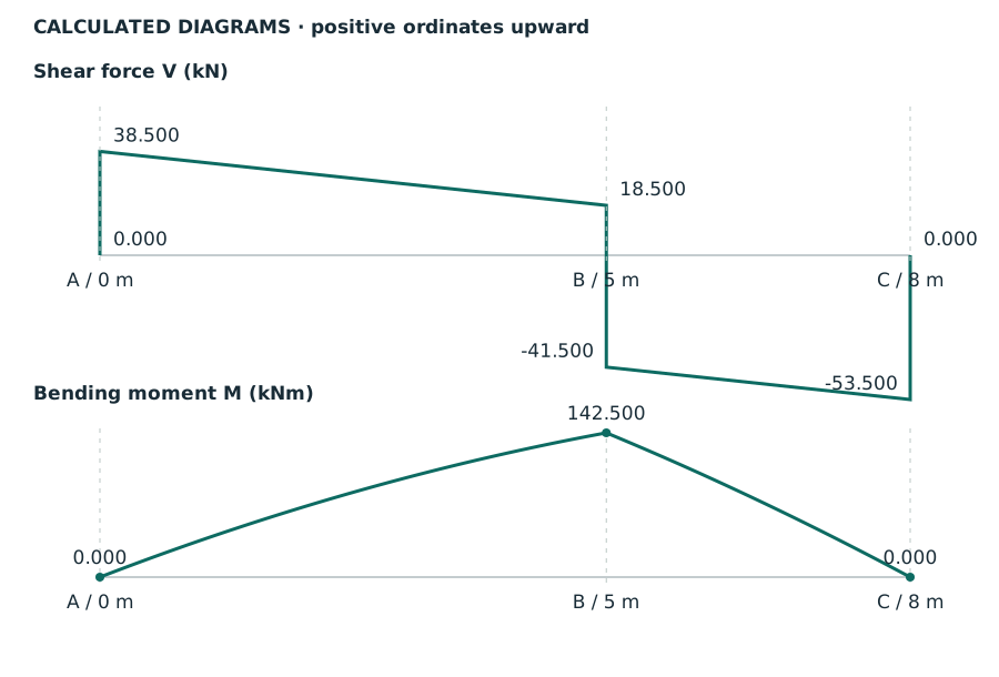
The SFD slopes downward at per metre on both intervals; its jump atB is . The BMD is parabolic between loads and has a change of slope atB. It has no jump because there is no applied point couple.
Animation labBuild the shear and moment diagrams
Supplement to the original lesson. Enable JavaScript to play, step through calculations and rotate 3D models. The following explanation remains readable offline.
- For the illustrative 60 kN point load on a 6 m simply supported beam, balance the reactions before making a cut.
- and before the point load. Moment grows linearly.
- Shear jumps down by P. To its right, and .
- For this case, moment is continuous and returns to zero at B. A concentrated applied couple instead creates a moment jump.
(c) AB lateral-torsional buckling using accurate parameters
Simple explanation: A beam can escape sideways
The compressed flange can move sideways while the section twists.
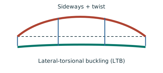
- Divide the beam at effective lateral restraints.
- Use each segment’s effective length to obtain its buckling resistance.
- Compare that resistance with the segment’s equivalent moment demand.
Remember: A section bending check alone does not check lateral-torsional buckling.
Within the AB segment, quarter points are 1.25,2.5 and 3.75 m fromA. The B point load acts at the segment end; it is accounted for throughRA and the maximum moment.
Normal-load effective length is the given segment length. All quantities in and λᴸᵀ are dimensionless. This Class 1 section has .
Table 8.3a, Data File p.5, pᵧ355 column:
AB passes under the stated normal-load/LE5 m assumption. The u value is 0.886 from this exact UB row; is calculated, not assumed .
Animation labA beam bends sideways and twists
Supplement to the original lesson. Enable JavaScript to play, step through calculations and rotate 3D models. The following explanation remains readable offline.
- For the illustrated sagging beam the top flange is compressed.
- The unrestrained compression flange can move sideways while the complete cross-section twists.
- Only effective restraints divide the member into unbraced segments. They do not automatically add vertical supports.
- Use the segment effective length, section properties and matching moment factor. This is an exaggerated mode shape, not a calculated displacement.
(d) Removing B changes stability but not vertical actions
Simple explanation: A support stops only certain movements
Holding a ruler up does not necessarily stop it sliding sideways or twisting.
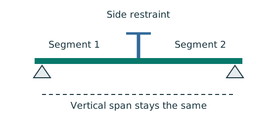
- Identify vertical support, lateral restraint and torsional restraint separately.
- Find which flange is in compression in each region.
- Use only restraints actually provided by the question.
Remember: An extra side restraint does not create a new vertical reaction.
Without the effective lateral restraint atB, the unrestrained segment becomes the full betweenA andC. The point load remains at , so the reactions and vertical SFD/BMD remain unchanged. Longer increases slenderness and reduces buckling resistance.
Normal-load effective length is the given segment length. All quantities in and λᴸᵀ are dimensionless. This Class 1 section has .
Table 8.3a, Data File p.5, pᵧ355 column:
The member remains a numerical narrow pass under the sameLE=actual/normal-load assumptions, but stability margin is substantially reduced. It is wrong to say that removing a restraint always forces failure; it always requires a new check. Other beam checks are outside the requested LTB calculation.
Animation labA beam bends sideways and twists
Supplement to the original lesson. Enable JavaScript to play, step through calculations and rotate 3D models. The following explanation remains readable offline.
- For the illustrated sagging beam the top flange is compressed.
- The unrestrained compression flange can move sideways while the complete cross-section twists.
- Only effective restraints divide the member into unbraced segments. They do not automatically add vertical supports.
- Use the segment effective length, section properties and matching moment factor. This is an exaggerated mode shape, not a calculated displacement.
Compact exam answer
, . Shear values: ; moment values: . AB: , , , , ; demand : passes. Remove B: , , ; full-span demand : still just passes. These LTB results assume normal loading and that equals the distance between restraints.
Mistakes to avoid
- Do not make B a vertical support.
- Do not use full-span quarter positions for AB.
- Do not discard the UDL in the moment ordinates.
- Do not state failure after restraint removal without recalculating.
Procedure for an unfamiliar variant
- Solve the original vertical system first.
- Mark lateral restraint positions separately.
- Find each segment’s maximum and local quarter moments.
- Readu,, and calculatev without early rounding.
- Change both effective length and moment factor when a restraint is removed.
Independent self-check
Try it yourself. Invented variant: all ultimate loads increase after restraintB is removed. Does the full-span LTB check still pass?
Reveal answer and reasoning
Yes, narrowly. Demand becomes , below . At increase, demand exceeds and fails. Maximum proportional increase. This comparison uses the original section and the stated stability assumptions.
Animation labA beam bends sideways and twists
Supplement to the original lesson. Enable JavaScript to play, step through calculations and rotate 3D models. The following explanation remains readable offline.
- For the illustrated sagging beam the top flange is compressed.
- The unrestrained compression flange can move sideways while the complete cross-section twists.
- Only effective restraints divide the member into unbraced segments. They do not automatically add vertical supports.
- Use the segment effective length, section properties and matching moment factor. This is an exaggerated mode shape, not a calculated displacement.