Mock Q2: full solution and invented marking guide
Open “Animation lab” beside a teaching step for a visual explanation or a walkthrough of its original expressions. Models are illustrative; source answers remain unchanged.
Need a simpler picture? Open “Simple explanation” beside a difficult step. These optional notes do not replace the full solution.
Return to question. All marking guidance is invented.
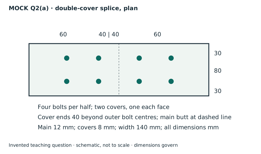
(a) Follow one splice half and every requested failure mode
Simple explanation: Count where the bolt can be sheared
The plate interfaces are the places trying to cut across the bolt.
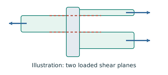
- Count actual loaded shear planes, not merely visible plates.
- Choose shank or threaded area for the plane concerned.
- Compare group resistance with the force that group transfers.
Remember: Bolts on opposite sides of a splice do not all act in parallel.
Simple explanation: Why holes reduce tension resistance
The pull must squeeze through the steel left beside the holes.
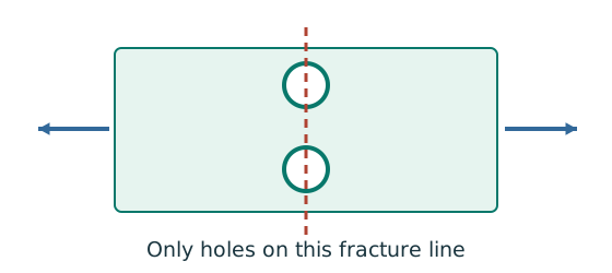
- Choose a possible fracture line across the member.
- Subtract the holes crossed by that line using hole diameter.
- Apply the course effective-area rule and its gross-area limit.
Remember: Do not subtract every hole anywhere in the connection.
Each transfer half carries the full . Four bolts share it: per bolt; each cover/plane takes . Eight bolts exist overall, but halves transfer load in series; do not divide by .
Connected-part bearing uses the least of all applicable terms. Main and cover end distances are ; clear hole ligament . Main web/plate load per bolt ; cover load per bolt .
A critical transverse tension section crosses TWO holes, one in each bolt line. Longitudinally separated holes are not all deducted at the same cut.
Longitudinal pitch ; transverse spacing .
Governing maximum spacing ; / both pass.
Maximum cover-plate edge distance ; passes. The thicker main plate permits a larger maximum edge distance.
Width check: .
All requested checks pass. Main net tension is the lowest calculated full-half resistance. This scoped result does not claim an unrequested complete block-shear design.
Animation labCount the bolt shear planes
Supplement to the original lesson. Enable JavaScript to play, step through calculations and rotate 3D models. The following explanation remains readable offline.
- Load must cross an interface between the connected plates.
- A lap joint gives one shear plane through a bolt.
- A symmetric double-cover joint may provide two shear planes. Count load-transfer interfaces, not just visible plates.
- Use the source’s area and shear strength. Then check bearing, plate resistance and detailing separately.
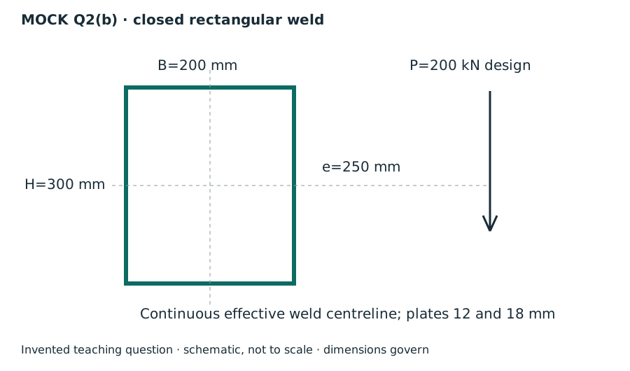
(b) Direct shear plus torsion at the reinforcing corner
Simple explanation: Only the weld lines resist as weld
Imagine a wire rectangle: its empty middle is not more wire.
- Count only the weld runs actually shown.
- Use their total length and line second moments.
- Combine direct and torsional forces at the critical location.
Remember: Line second moments have units ; plate-area moments use .
Simple explanation: Add arrows before taking the magnitude
Walking east and walking north do not point in the same direction.
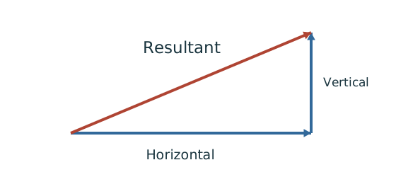
- Choose signed horizontal and vertical directions.
- Add contributions along each direction separately.
- For perpendicular components, use the right-triangle resultant.
Remember: Check the corner where direct and torsional components reinforce each other.
Use the weld-length centroid at the rectangle centre. Corner , . Direct downward shear adds to torsional vertical shear on one side; that side governs. Weld-line inertias have units of .
The strength requirement alone would permit a small leg, but the thicker plate gives minimum . At the thinner edge maximum=. Choose : qcap 1.05 kN/mm, which exceeds the calculated demand. This closed effective-line mock does not use two-end deductions on each rectangle side; the geometry was expressly defined as continuous.
Animation labA weld group is a set of lines
Supplement to the original lesson. Enable JavaScript to play, step through calculations and rotate 3D models. The following explanation remains readable offline.
- The centre is empty: resistance comes from the weld lines, not a solid plate filling the group.
- Use line lengths for centroid weighting. Line second moments have units ; add the parallel-axis terms.
- Direct force per length is . The eccentric moment adds tangential flow proportional to distance from the centroid.
- Combine signed components at every candidate corner, then compare the maximum with throat resistance per length.
Compact script and invented marking guide
(a) Four bolts/half, double shear:; bolt bearing ; main plate bearing ; main tension ; each cover bearing and tension . All exceed corresponding / actions; layout passes. (b) ; strength leg; detailing governs choose .
Invented credit: (a) force sharing , bolt checks , connected-part bearing , tension , layout/conclusion . (b) centroid/eccentric moment , length/inertias , corner components/resultant , size/detail/conclusion .
Animation labFollow the calculation sequence
Supplement to the original lesson. Enable JavaScript to play, step through calculations and rotate 3D models. The following explanation remains readable offline.
- Locate the load, supports, connection geometry and any stated assumptions.
- Keep given values, table lookups and calculated values distinct; reconcile their units.
- The calculation player steps through the existing expressions in their original order.
- Compare demand with resistance or the relevant limit. Keep missing inputs and conditional conclusions explicit.