Mock Q3: full solution and invented marking guide
Open “Animation lab” beside a teaching step for a visual explanation or a walkthrough of its original expressions. Models are illustrative; source answers remain unchanged.
Need a simpler picture? Open “Simple explanation” beside a difficult step. These optional notes do not replace the full solution.
Return to question. All marking guidance is invented.
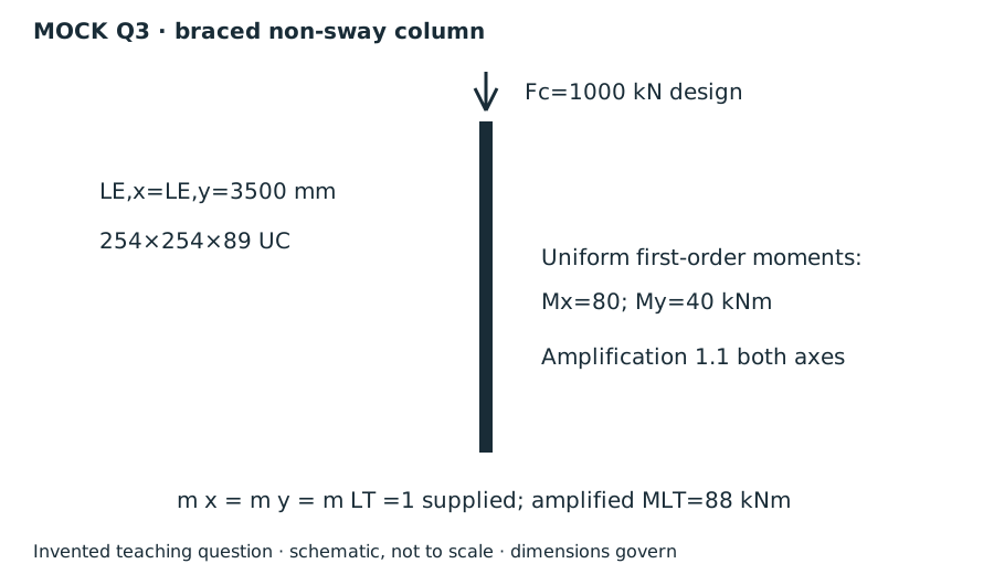
Lookup: Data File p.11, exact row UC. Read the dimensions/local ratios table and the properties table separately. The axis crosses the web horizontally; passes vertically through its centre in the table sketch.
| Property | Value and units |
|---|---|
| Flange/web/root-to-root web depth | 、、。 |
| Local slenderness | 、。 |
| Radii (converted from ) | ;。 |
| Area | 。 |
| Elastic moduli | ;。 |
| Plastic moduli | ;。 |
| LTB parameters | , ; both dimensionless |
(a) Classify before choosing resistance
Simple explanation: A thin part can wrinkle first
A thin plate may wrinkle before the whole steel member reaches its intended resistance.
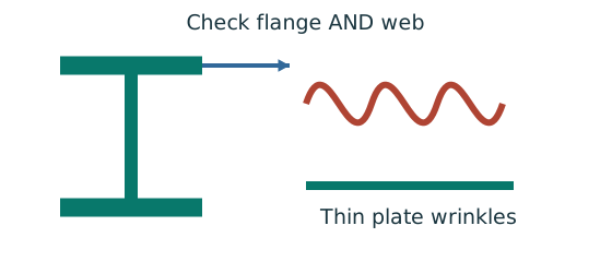
- Check flange and web slenderness using their own definitions.
- Compare each ratio with the correct class limits.
- The less favourable element determines the section class.
Remember: Bending limits and uniform-compression limits are different.
Web stress parameter: Using is capped to give . For any in this range, the conservative Class 1 web limit is . . The web satisfies this stricter limit. Overall Class 1; use capped plastic section resistance.
The lecture’s Class 1 combined-stress web limit cannot be below because . This check therefore avoids an unjustified plastic classification while remaining conservative. The flange is checked independently.
Animation labWhy thin elements buckle locally
Supplement to the original lesson. Enable JavaScript to play, step through calculations and rotate 3D models. The following explanation remains readable offline.
- The flange outstand and web have different widths, thicknesses and edge support conditions.
- A thinner plate can wrinkle locally before the complete member loses stability.
- Class 1 allows plastic rotation; Class 2 reaches plastic resistance; Class 3 reaches elastic resistance; Class 4 requires effective properties.
- Check every relevant compression element with the supplied limits and stress distribution. The deformation shown is qualitative.
(b) Cross-section interaction
Simple explanation: The column needs more than one pass
A slice can be strong while the whole member still buckles.
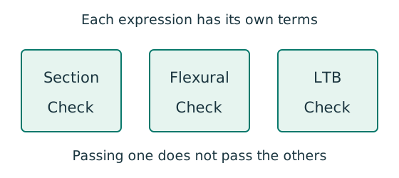
- Check cross-section compression plus bending.
- Then check the separate member-buckling expressions.
- Keep each moment, factor and resistance in its specified expression.
Remember: The three checks do not share interchangeable denominators.
At a cross section, compression and bending share the material. Use amplified moments and capped plastic resistances. The total must not exceed ; all terms below are dimensionless.
Animation labA strong slice can belong to an unstable member
Supplement to the original lesson. Enable JavaScript to play, step through calculations and rotate 3D models. The following explanation remains readable offline.
- Combine axial compression and the two bending demands using the specified section resistances.
- The whole member adds effective-length and buckling-curve effects.
- This uses its own moment factor and bending resistance; it is not a copy of the section check.
- Elastic, plastic and buckling resistances are not interchangeable. Read the three original expressions and their first-order/amplified moments.
(c) Flexural member interaction
Simple explanation: Why a long column can fail before crushing
Push a long thin ruler from both ends: it may bow sideways first.
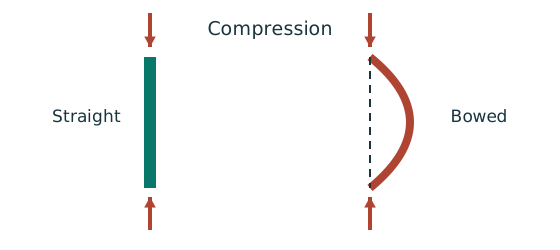
- Find effective length and radius of gyration for each axis.
- Calculate slenderness for both directions.
- Use the appropriate buckling curve before forming resistance.
Remember: Compare the final resistances; slenderness alone may not identify the controlling axis.
Table 8.7: hot-rolled H-section (UC), maximum thickness , about the axis use curve , about the axis use curve . Use the Data File p.8 column. The two axes use different curves, so slenderness alone cannot identify the governing axis.
Member interaction uses elastic moment denominators pᵧZ, even when the cross-section check used plastic moduli. Use amplified moments here.
Animation labA strong slice can belong to an unstable member
Supplement to the original lesson. Enable JavaScript to play, step through calculations and rotate 3D models. The following explanation remains readable offline.
- Combine axial compression and the two bending demands using the specified section resistances.
- The whole member adds effective-length and buckling-curve effects.
- This uses its own moment factor and bending resistance; it is not a copy of the section check.
- Elastic, plastic and buckling resistances are not interchangeable. Read the three original expressions and their first-order/amplified moments.
(c) LTB interaction
Simple explanation: A beam can escape sideways
The compressed flange can move sideways while the section twists.
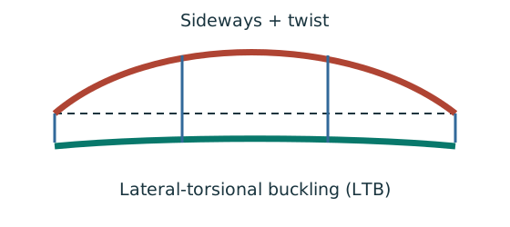
- Divide the beam at effective lateral restraints.
- Use each segment’s effective length to obtain its buckling resistance.
- Compare that resistance with the segment’s equivalent moment demand.
Remember: A section bending check alone does not check lateral-torsional buckling.
Continuous/non-sway member: Class 1/2 gives . Use the full – calculation with the stated effective length.
Read Data File p.5 Table 8.3a, pᵧ345 column:
Course Eq.8.81 uses first-order minor-axis moment in its last term. Mᴸᵀ is the specified amplified major-axis value; do not amplify it twice. The axial denominator is .
Animation labA strong slice can belong to an unstable member
Supplement to the original lesson. Enable JavaScript to play, step through calculations and rotate 3D models. The following explanation remains readable offline.
- Combine axial compression and the two bending demands using the specified section resistances.
- The whole member adds effective-length and buckling-curve effects.
- This uses its own moment factor and bending resistance; it is not a copy of the section check.
- Elastic, plastic and buckling resistances are not interchangeable. Read the three original expressions and their first-order/amplified moments.
Compact script and invented marking guide
; , ; , ; . Interaction ratios: section , flexural buckling , axial force/LTB . All three requested strength checks pass.
Invented credit: classification ; section properties/amplification and interaction ; curves/slenderness , compression interpolation , flexural equation/result , accurate LTB calculation , second interaction/conclusion . Do not multiply the supplied by again.
Animation labFollow the calculation sequence
Supplement to the original lesson. Enable JavaScript to play, step through calculations and rotate 3D models. The following explanation remains readable offline.
- Locate the load, supports, connection geometry and any stated assumptions.
- Keep given values, table lookups and calculated values distinct; reconcile their units.
- The calculation player steps through the existing expressions in their original order.
- Compare demand with resistance or the relevant limit. Keep missing inputs and conditional conclusions explicit.