Timed mock: questions only
Open “Animation lab” beside a teaching step for a visual explanation or a walkthrough of its original expressions. Models are illustrative; source answers remain unchanged.
This entire mock, its diagrams, model answers and mark scheme are invented teaching material. It follows the supplied two-hour format; it is not an official paper or a prediction. Answer Q1 ( marks) and any TWO of Q2/Q3/Q4 ( marks each). Total required marks. Use the supplied local data tables and a calculator. Do not reveal answers until the minutes end.
All steel is S355. . Use the supplied HK course methods, not a different standard. Where loads are marked “design”, they are already factored. Suggested time: read/select min; Q1 min; each option min; final check min.
Q1 · compulsory ·40 marks
Reinforced-concrete slab thickness , unit weight . Finishes add , and the imposed load is . In plan, three transverse B1 beams bound two slab bays, each spanning . Each B1 spans onto the B2 edge beams drawn vertically in the plan. Each B2 spans between corner columns; the middle B1 connects at its midspan. Design the middle B1 and one B2. B1 is UB (tabulated mass ); B2 is UB (). Use . Both are simply supported, fully laterally restrained by the slab, and carry brittle finishes. Do not assume composite stiffness. The requested scope is shear, bending and imposed-load deflection; local connection/web-contact design is not required.
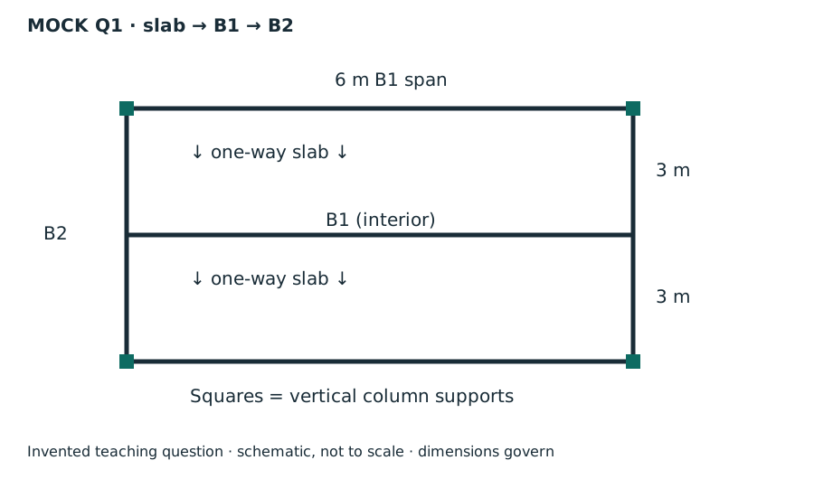
- (a) Calculate characteristic dead and ultimate slab intensity. [4]
- (b) Calculate both beam design load models, reactions and maximum moments. [8]
- (c) Classify both sections. [4]
- (d) Check B1 shear, bending and imposed-load deflection. [10]
- (e) Check B2 shear, bending and imposed-load deflection. [10]
- (f) Explain two differences between strength and stiffness. [4]
Animation labFollow the floor load in 3D
Supplement to the original lesson. Enable JavaScript to play, step through calculations and rotate 3D models. The following explanation remains readable offline.
- The floor carries pressure in . The highlighted strip belongs to one secondary beam.
- Multiply pressure by tributary width: . The illustration uses .
- A primary beam receives the secondary beam reaction at their connection, not a new full-span UDL.
- Trace reactions down to columns and foundations. Count each loaded area once.
Q2 · optional ·30 marks
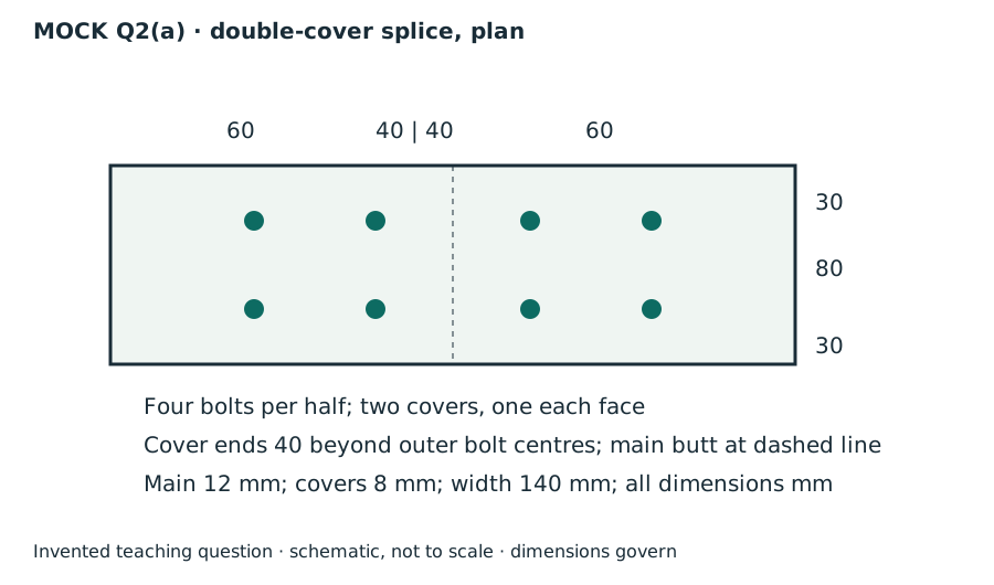
(a) A300 kN design tension is transferred by a symmetric double-cover splice. Main plate , two covers each, width throughout. There are fourM20 Grade 8.8 bolts on each side of the butt, in two lines and two longitudinal rows. Standard holes . Along each half: main end distance , pitch ; each cover extends beyond the outer bolt centre. Gauge and transverse edges . All edges are rolled. Threads cross both shear planes. Check bolt shear and bolt bearing, main/cover connected-part bearing and net tension, and spacing. UseKe 1.1,pbs 550,Us 510,Ub 800. Supporting members and block-shear paths are outside the requested scope. [18]
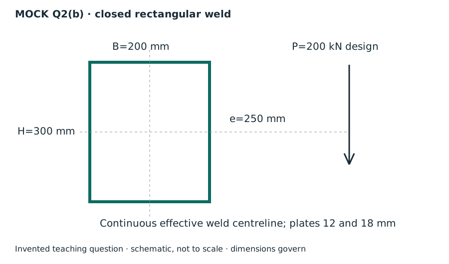
(b) A continuous closed rectangular fillet-weld line wide by high carries a design downward force whose line is right of the weld centroid. Plate thicknesses and ; S355/Class 42 electrode. Treat the given rectangle as the effective line. Calculate the governing corner line force and choose a fillet leg satisfying strength and the supplied minimum/maximum size rules. []
Animation labCount the bolt shear planes
Supplement to the original lesson. Enable JavaScript to play, step through calculations and rotate 3D models. The following explanation remains readable offline.
- Load must cross an interface between the connected plates.
- A lap joint gives one shear plane through a bolt.
- A symmetric double-cover joint may provide two shear planes. Count load-transfer interfaces, not just visible plates.
- Use the source’s area and shear strength. Then check bearing, plate resistance and detailing separately.
Q3 · optional ·30 marks
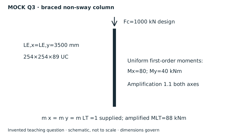
A braced, non-sway UC carries design compression . Effective length about both axes is . Uniform first-order moments act about the axes as follows: axis by and about axis by ; the amplification factor for each axis is . A separate equivalent amplified major-axis LTB moment is given as . All moment factors . Use exact , and the course non-sway expressions. (a) Section classification [4]; (b) cross-section interaction [6]; (c) both member-buckling interaction checks [20].
Animation labEffective length and buckling axes
Supplement to the original lesson. Enable JavaScript to play, step through calculations and rotate 3D models. The following explanation remains readable offline.
- A column can bow sideways before its section reaches the crushing resistance.
- Each axis has its own radius of gyration and restraint spacing.
- , with compatible length units. A tie affects only the directions it actually restrains.
- Select each buckling curve and compressive strength before forming Pc. The governing axis is determined by resistance, not slenderness alone.
Q4 · optional ·30 marks
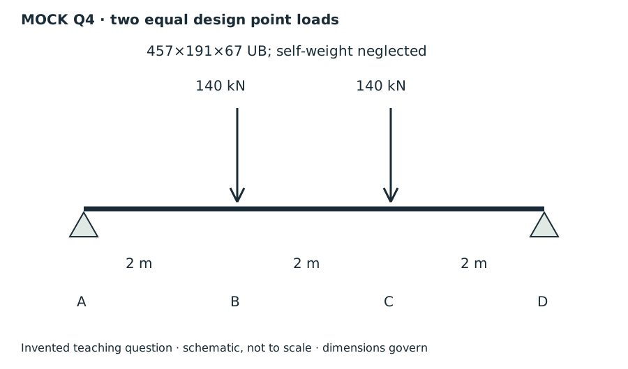
Simply supported of length UB, with locations and each carrying a design point load. Ignore self-weight. Loading is normal; both ends restrain torsion and allow free in-plane rotation. LTB effective lengths equal the stated spacings between lateral restraints. (a) Find reactions and draw shear-force and bending-moment diagrams [4]. (b) With lateral restraints only at A/D, check shear, low-shear bending and LTB using exact , and quarter-point [16]. (c) Add adequate lateral restraint at B/C and check each LTB segment [10]. Local web/connection checks and deflection are outside this question.
Animation labA beam bends sideways and twists
Supplement to the original lesson. Enable JavaScript to play, step through calculations and rotate 3D models. The following explanation remains readable offline.
- For the illustrated sagging beam the top flange is compressed.
- The unrestrained compression flange can move sideways while the complete cross-section twists.
- Only effective restraints divide the member into unbraced segments. They do not automatically add vertical supports.
- Use the segment effective length, section properties and matching moment factor. This is an exaggerated mode shape, not a calculated displacement.
After the timer ends
Stop writing at minutes. Then open the separate answers: Q1 · Q2 · Q3 · Q4. Mark onlyQ1 plus your chosen two options for a -mark score. The other option is useful untimed practice.
Animation labFollow the calculation sequence
Supplement to the original lesson. Enable JavaScript to play, step through calculations and rotate 3D models. The following explanation remains readable offline.
- Locate the load, supports, connection geometry and any stated assumptions.
- Keep given values, table lookups and calculated values distinct; reconcile their units.
- The calculation player steps through the existing expressions in their original order.
- Compare demand with resistance or the relevant limit. Keep missing inputs and conditional conclusions explicit.