Short theory: 4 marks you can learn by heart
The last part of Section A is usually a 4-mark theory question. There are only a few topics, and they repeat. They are listed below by how often they appeared in the 16 papers, each with a short explanation and a model answer to learn.
How often each topic appeared (16 papers, 2014–2024)
| Topic | Times | Priority |
|---|---|---|
| Fire protection: sketch two methods | 4 | ★★★ |
| Second-order effects P–Δ and P–δ | 3 | ★★★ |
| Hot-rolled sections: sketch and name | 2 | ★★ |
| Corrosion protection: two methods | 2 | ★★ |
| Limit states (ULS / SLS): examples | 2 | ★★ |
| Purpose of classification | 1 | ★ |
| Load–displacement curves of four analysis types | 1 | ★ |
Fire protection Always examined
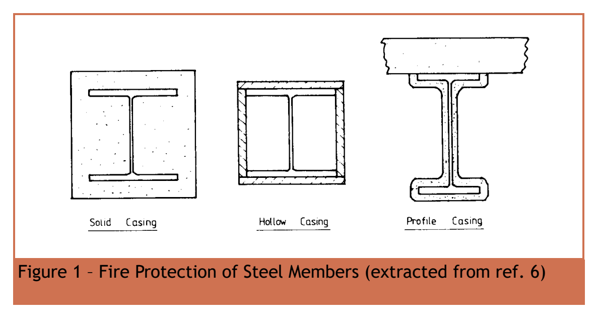
| Method | How to sketch | Example |
|---|---|---|
| Solid casing | a rectangle around the I-section, completely filled (hatched) | concrete encasement |
| Hollow casing | a rectangular outline around the I-section, empty inside | fire boards forming a box |
| Profile casing | a thin layer that follows the I shape | sprayed coating, intumescent paint |
Concept map
Fire protection: why wrap the steel, and how to sketch the three methods
The most frequent theory question (4 times in 16 papers). Understand the cause — steel softens when hot — and the three methods become three ways of doing the same thing: insulation.
- Cause
- Key idea
- Result
- How design deals with it
- Exam answer
- marks are often lost here
Text version (from cause to result)
Cause
A fire heats the steel
Steel conducts heat well, so it heats up quickly in a fire.
Comes from (upstream)— (a starting point)
Leads to (downstream)Steel softens: strength and stiffness drop
Key idea
Steel softens: strength and stiffness drop
The hotter the steel, the lower its strength and stiffness. At a critical temperature the member can no longer carry its load.
Comes from (upstream)A fire heats the steel
Leads to (downstream)Members fail → collapse, less time to escape
Result
Members fail → collapse, less time to escape
Beams and columns fail early; the structure may collapse before people can get out.
Comes from (upstream)Steel softens: strength and stiffness drop
Leads to (downstream)The principle: insulate to delay heating
How design deals with it
The principle: insulate to delay heating
Fire protection does not stop the steel heating; it gives it an insulating coat that delays it reaching the critical temperature, buying time.
Comes from (upstream)Members fail → collapse, less time to escape
Leads to (downstream)Solid casingHollow casingProfile casing
How design deals with it
Solid casing
The whole I-section is encased in solid material, e.g. concrete. Sketch: the I-section inside a filled (hatched) rectangle.
Comes from (upstream)The principle: insulate to delay heating
Leads to (downstream)Exam: one-line principle + sketch two
How design deals with itWhere marks are lost
Hollow casing
Fire boards form a box around the I-section with an air space inside. Sketch: the I-section inside a rectangular outline.
Comes from (upstream)The principle: insulate to delay heating
Leads to (downstream)Exam: one-line principle + sketch two
How design deals with it
Profile casing
A sprayed coating or intumescent paint forms a thin layer following the I shape. Sketch: a thin layer drawn around the I outline.
Comes from (upstream)The principle: insulate to delay heating
Leads to (downstream)Exam: one-line principle + sketch two
Exam answerWhere marks are lost
Exam: one-line principle + sketch two
Write the principle in one line, then sketch two methods. Draw the I-section in every sketch and label it. The lecture gives no thickness or fire rating, so do not invent numbers.
Comes from (upstream)Solid casingHollow casingProfile casing
Leads to (downstream)— (the last step)
Tour steps
1. Why protect against fire?
Fire → steel heats up → strength and stiffness drop → members fail.
In this stepA fire heats the steelSteel softens: strength and stiffness dropMembers fail → collapse, less time to escape
2. One principle: insulation
The aim is to delay the steel heating, buying time for escape and fire-fighting.
In this stepThe principle: insulate to delay heating
3. Three ways to do it
Solid (filled), hollow (an outline), profile (a thin layer following the shape). The difference is all in the outline you draw.
In this stepSolid casingHollow casingProfile casing
4. The exam answer
One line of principle + two labelled sketches is the skeleton of a full-mark answer.
In this stepExam: one-line principle + sketch two
Second-order effects: P–Δ and P–δ Always examined
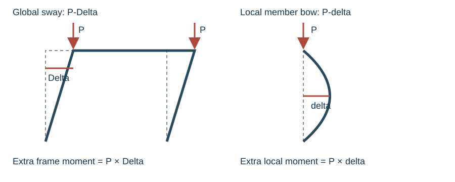
| P–Δ (capital Delta) | P–δ (small delta) | |
|---|---|---|
| What moves? | a whole storey / the frame sways | one member bows between its ends |
| Extra moment |
Concept map
P–Δ and P–δ: why deformation makes the moment bigger
One of the most frequent theory questions (3 times in 16 papers). Read from top to bottom: compression plus an offset → the two effects → the snowball → how analysis and design deal with it → the exam answer.
- Cause
- Key idea
- Result
- What changes it
- How design deals with it
- Exam answer
- marks are often lost here
Text version (from cause to result)
Cause
Axial compression
A column carries a large compression . As soon as it does not push straight down the centre line, it adds a moment.
Comes from (upstream)— (a starting point)
Leads to (downstream) P–Δ effect (global) P–δ effect (member)
Cause
The frame sways
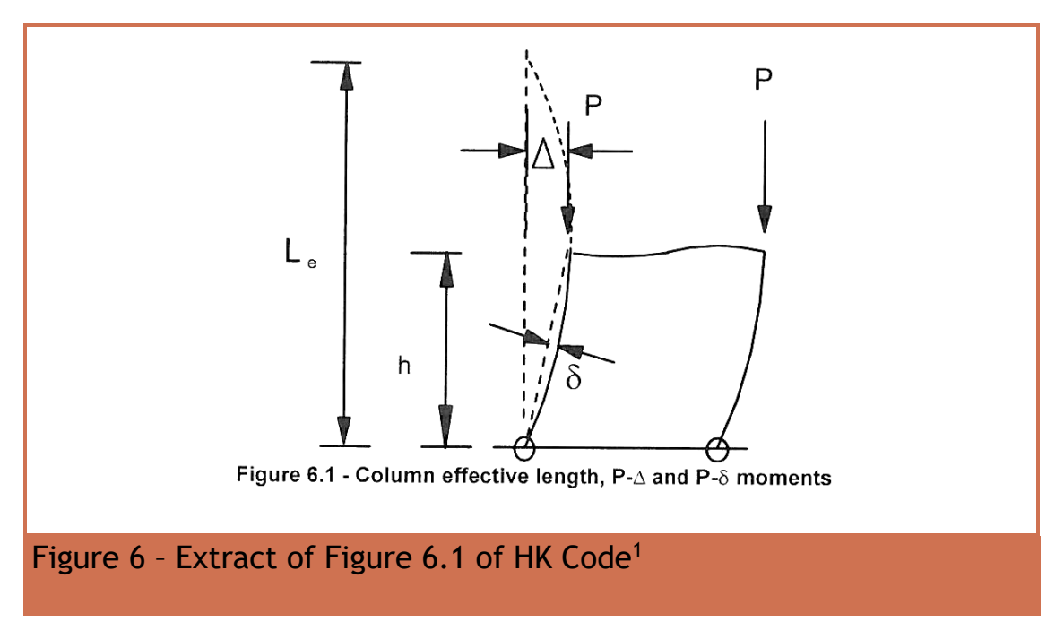
Horizontal loads such as wind, or a frame that is not perfectly plumb (design assumes a lean of ), move the top of a storey sideways by relative to its base.
Source: Lecture: global imperfection , or a notional horizontal force of 0.5% of the vertical load.
Comes from (upstream)— (a starting point)
Leads to (downstream) P–Δ effect (global)
Cause
The member bows
No member is perfectly straight (initial bow about to , depending on the buckling curve), and it bows out by between its ends under moment.
Comes from (upstream)— (a starting point)
Leads to (downstream) P–δ effect (member)
Key idea
P–Δ effect (global)
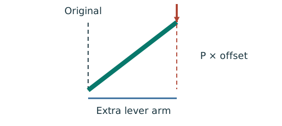
The compression acts through the storey sway and creates an extra moment . It is an effect of the whole frame.
Comes from (upstream) Axial compression The frame sways
Leads to (downstream)A snowball: more bending, more moment How far from instabilityExam answer: definition + both effects + sketch
Key ideaWhere marks are lost
P–δ effect (member)
The compression acts through the member’s own bow and creates an extra moment . It is an effect of one member.
Comes from (upstream) Axial compression The member bows
Leads to (downstream)A snowball: more bending, more momentExam answer: definition + both effects + sketch
Result
A snowball: more bending, more moment
The extra moment bends the member more, the offset grows, and so does the extra moment. Deflections increase, stiffness drops, and in the worst case the frame becomes unstable.
Comes from (upstream) P–Δ effect (global) P–δ effect (member)
Leads to (downstream)Second-order analysis: equilibrium on the deformed shape Amplification factor: add it in one go
How design deals with it
Second-order analysis: equilibrium on the deformed shape
First-order analysis writes equilibrium on the original, undeformed shape and misses the extra moments; second-order analysis writes it on the deformed shape and includes them. A P–Δ–δ analysis also includes member bow and imperfections.
Comes from (upstream)A snowball: more bending, more moment
Leads to (downstream)Four load–displacement curvesExam answer: definition + both effects + sketch
What changes itWhere marks are lost
How far from instability
The elastic critical load factor: how many times the loads must be multiplied before the frame becomes unstable. is non-sway and P–Δ may be simplified; is ultra-sensitive and needs second-order or advanced analysis.
Source: Columns lecture section 5
Comes from (upstream) P–Δ effect (global)
Leads to (downstream) Amplification factor: add it in one go
Exam answer
Four load–displacement curves
First-order elastic: a straight line; second-order elastic: stiffness gradually drops; first-order plastic: reaches a plateau (mechanism); second-order elastic-plastic: a lower peak, then the load falls.
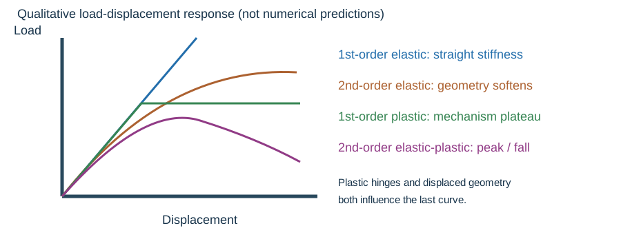
Source: Short theory: four analysis types (asked once)
Comes from (upstream)Second-order analysis: equilibrium on the deformed shape
Leads to (downstream)— (the last step)
How design deals with itWhere marks are lost
Amplification factor: add it in one go
Without a second-order analysis, multiply the first-order moment by an amplification factor to include the extra moment. Exam questions usually give the factor (e.g. 1.1).
Source: How it is used: columns crash course.
Comes from (upstream)A snowball: more bending, more moment How far from instability
Leads to (downstream)— (the last step)
Exam answer
Exam answer: definition + both effects + sketch
Write one definition (equilibrium on the deformed shape), one line each for P–Δ and P–δ, and a sketch: a frame swaying by on the left and a column bowing by on the right.
Comes from (upstream) P–Δ effect (global) P–δ effect (member)Second-order analysis: equilibrium on the deformed shape
Leads to (downstream)— (the last step)
Tour steps
1. The cause: compression plus an offset
Compression alone adds no moment; it must act through an offset. There are two kinds of offset: storey sway or member bow .
In this step Axial compression The frame sways The member bows
2. The two effects
Compression × storey sway = P–Δ (global); compression × member bow = P–δ (member).
In this step P–Δ effect (global) P–δ effect (member)
3. The snowball
Extra moment → more deformation → more extra moment. That is why it cannot be ignored.
In this stepA snowball: more bending, more moment
4. Analysis
First-order analysis cannot see it; second-order analysis works on the deformed shape. The four analysis curves may also be asked on their own.
In this stepSecond-order analysis: equilibrium on the deformed shapeFour load–displacement curves
5. How design deals with it
Use to judge how sensitive the frame is; in calculations multiply the first-order moment by the amplification factor, once only.
In this step How far from instability Amplification factor: add it in one go
6. The exam answer
Definition + P–Δ + P–δ + sketch, about 4 marks. No essay needed.
In this stepExam answer: definition + both effects + sketch
Hot-rolled sections Often examined
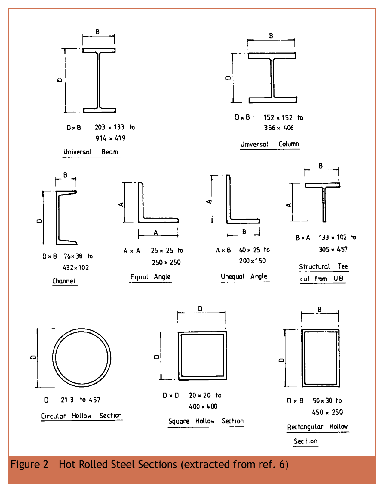
| Name | Shape | Typical use |
|---|---|---|
| Universal Beam (UB) | “I” shape, deep and narrow | beams: efficient in strong-axis bending |
| Universal Column (UC) | “H” shape, width ≈ depth | columns: strong in both directions |
| Channel | “[” or C shape | bracing, secondary members, compound sections |
| Angle | “L” shape, equal or unequal legs | bracing, trusses, connection pieces |
Concept map
Hot-rolled sections: the shape decides the job
The theory question “sketch and name four hot-rolled sections” has been asked twice. Once you see where the steel sits, it is clear why a UB is a beam and a UC a column — and how links to LTB and column buckling.
- Cause
- Key idea
- Result
- What changes it
- Exam answer
- marks are often lost here
Text version (from cause to result)
Cause
Steel far from the axis works hardest
In bending, steel far from the neutral axis carries the most stress with the longest lever arm. That is why an I shape puts most of its steel in the flanges.
Comes from (upstream)— (a starting point)
Leads to (downstream), , , Section properties come from the shape
Key idea
, , , Section properties come from the shape
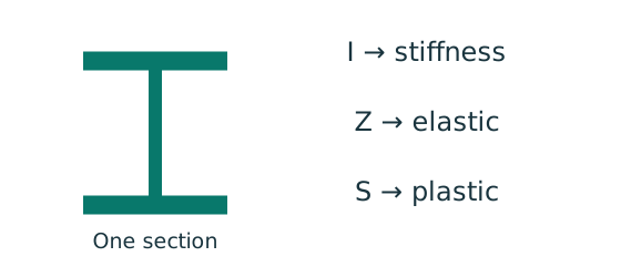
governs stiffness (deflection), the elastic moment, the plastic moment, and buckling. They are not interchangeable.
Comes from (upstream)Steel far from the axis works hardest
Leads to (downstream)Strong axis x–x, weak axis y–yChannelAngle
Key idea
Strong axis x–x, weak axis y–y
For the same section and about are far larger than about . In this course is always the strong axis.
Comes from (upstream), , , Section properties come from the shape
Leads to (downstream)UB: deep and narrow → beamsUC: wide flanges, width ≈ depth → columns
What changes it
How to read a section name
356×127×39 UB: about 356 mm deep, 127 mm wide, 39 kg per metre (self-weight ). These are nominal; read the real dimensions from the table row.
Comes from (upstream)— (a starting point)
Leads to (downstream)UB: deep and narrow → beams
Result
UB: deep and narrow → beams
Very efficient in strong-axis bending; but the narrow flanges give a small , so it is prone to LTB and needs lateral restraint (see the LTB concept map).
Comes from (upstream)Strong axis x–x, weak axis y–yHow to read a section name
Leads to (downstream)Exam: sketch and name four
Result
UC: wide flanges, width ≈ depth → columns
Stocky in both directions, so is not too small — suited to compression and bending both ways (see the column-buckling map).
Comes from (upstream)Strong axis x–x, weak axis y–y
Leads to (downstream)Exam: sketch and name four
Result
Channel
“[” shape: one web with both flanges on the same side. Used for bracing, secondary members and compound sections.
Comes from (upstream), , , Section properties come from the shape
Leads to (downstream)Exam: sketch and name four
Result
Angle
“L” shape with equal or unequal legs. Used in bracing, trusses and connection pieces. Connected through one leg it needs a deduction (see the net-area map).
Comes from (upstream), , , Section properties come from the shape
Leads to (downstream)Exam: sketch and name four
Exam answerWhere marks are lost
Exam: sketch and name four
The safest four: UB, UC, channel and angle. Sketch each cross-section, label it and give one line on its use.
Comes from (upstream)UB: deep and narrow → beamsUC: wide flanges, width ≈ depth → columnsChannelAngle
Leads to (downstream)— (the last step)
Tour steps
1. Where the steel sits
The further from the axis the more useful, so the shape sets .
In this stepSteel far from the axis works hardest, , , Section properties come from the shape
2. Strong and weak axes
Strong about , weak about — that is what separates beams from columns.
In this stepStrong axis x–x, weak axis y–y
3. UB for beams, UC for columns
A UB is deep and narrow — efficient in bending but with a small ; a UC is stocky both ways.
In this stepHow to read a section nameUB: deep and narrow → beamsUC: wide flanges, width ≈ depth → columns
4. Channels and angles
Mostly for bracing, trusses and connections.
5. The exam answer
Four labelled sketches, one line of use each.
In this stepExam: sketch and name four
Corrosion protection Often examined
| Method | How it protects |
|---|---|
| Paint coating | forms a barrier that keeps out moisture and air |
| Galvanizing (zinc or aluminium coating) | the zinc layer isolates the steel and corrodes first, sacrificing itself |
| Cathodic protection | for structures permanently in water; reduces electrochemical corrosion |
| Weathering steel | its alloy forms a stable protective oxide layer |
Concept map
Corrosion protection: why steel rusts, and the two ways to stop it
The question asks for two methods. The key is that they must work differently: one keeps water and air away, the other lets another metal corrode instead of the steel.
- Cause
- Key idea
- Result
- How design deals with it
- Exam answer
- marks are often lost here
Text version (from cause to result)
Cause
Moisture + oxygen
Steel is exposed to damp air or water.
Comes from (upstream)— (a starting point)
Leads to (downstream)Electrochemical corrosion: rust
Key idea
Electrochemical corrosion: rust
The iron in the steel reacts electrochemically with water and oxygen and slowly turns into rust.
Comes from (upstream)Moisture + oxygen
Leads to (downstream)Thinner section, less strength
Result
Thinner section, less strength
Rust eats the steel away; the effective section gets thinner and weaker, and durability suffers (a serviceability limit state, SLS).
Comes from (upstream)Electrochemical corrosion: rust
Leads to (downstream)Two ideas: barrier / sacrifice
Key idea
Two ideas: barrier / sacrifice
(1) Barrier: keep water and air away from the steel; (2) sacrifice: let another metal (e.g. zinc) corrode instead of the steel.
Comes from (upstream)Thinner section, less strength
Leads to (downstream)Paint coating (barrier)Hot-dip galvanizing (barrier + sacrifice)Cathodic protection (immersed)Weathering steel (material choice)
How design deals with it
Paint coating (barrier)
A paint system forms a barrier on the surface that keeps out moisture and oxygen.
Comes from (upstream)Two ideas: barrier / sacrifice
Leads to (downstream)Exam: two methods that work differently
How design deals with it
Hot-dip galvanizing (barrier + sacrifice)
The zinc layer both isolates the steel and corrodes first, sacrificing itself to protect the steel.
Comes from (upstream)Two ideas: barrier / sacrifice
Leads to (downstream)Exam: two methods that work differently
How design deals with it
Cathodic protection (immersed)
For structures permanently in water; it reduces electrochemical corrosion.
Comes from (upstream)Two ideas: barrier / sacrifice
Leads to (downstream)Exam: two methods that work differently
How design deals with it
Weathering steel (material choice)
Its alloy content forms a stable protective oxide layer. It is a choice of steel, not a coating.
Comes from (upstream)Two ideas: barrier / sacrifice
Leads to (downstream)Exam: two methods that work differently
Exam answerWhere marks are lost
Exam: two methods that work differently
One line each on how it protects. The safest pair: paint (barrier) + galvanizing (sacrifice), or add cathodic protection.
Comes from (upstream)Paint coating (barrier)Hot-dip galvanizing (barrier + sacrifice)Cathodic protection (immersed)Weathering steel (material choice)
Leads to (downstream)— (the last step)
Tour steps
1. Why does steel rust?
Moisture + oxygen → electrochemical reaction → rust → a thinner section.
In this stepMoisture + oxygenElectrochemical corrosion: rustThinner section, less strength
2. Two ideas
Cut off the cause (keep water and air out), or find a stand-in (a sacrificial metal).
In this stepTwo ideas: barrier / sacrifice
3. Four methods
Paint, galvanizing, cathodic protection, weathering steel — which idea does each belong to?
In this stepPaint coating (barrier)Hot-dip galvanizing (barrier + sacrifice)Cathodic protection (immersed)Weathering steel (material choice)
4. The exam answer
Pick two methods that work differently and give one line each on how they protect.
In this stepExam: two methods that work differently
Limit states (ULS and SLS) Often examined
| ULS (safety) | SLS (use) |
|---|---|
| bending or shear failure of a beam (yielding) | excessive deflection cracking finishes |
| buckling of a column | excessive vibration causing discomfort |
| overturning or sliding | wind-induced oscillation |
| brittle fracture, fatigue | durability (e.g. corrosion) |
Concept map
Limit states: “will it collapse?” and “does it work?” are two different routes
ULS and SLS are not only a theory question (asked twice); they decide which load each calculation uses: strength with factored loads, deflection with unfactored loads. This map links the two.
- Cause
- Key idea
- Result
- How design deals with it
- Exam answer
- marks are often lost here
Text version (from cause to result)
Cause
Limit state
A condition beyond which the structure no longer meets a design requirement. Design makes sure none of them is reached.
Comes from (upstream)— (a starting point)
Leads to (downstream)ULS: will it collapse?SLS: does it work in everyday use?
Key idea
ULS: will it collapse?
Ultimate limit state: safety — collapse or damage that cannot be repaired.
Comes from (upstream)Limit state
Leads to (downstream)ULS examples ULS uses factored loads
Key idea
SLS: does it work in everyday use?
Serviceability limit state: it does not collapse, but it does not work properly in normal use.
Comes from (upstream)Limit state
Leads to (downstream)SLS examples SLS uses unfactored loads
Result
ULS examples
Bending or shear failure of a beam (yielding), column buckling, overturning or sliding, brittle fracture, fatigue, fire.
Comes from (upstream)ULS: will it collapse?
Leads to (downstream)Theory question: definition + two examples each
Result
SLS examples
Excessive deflection cracking finishes, vibration causing discomfort, wind-induced oscillation, durability (e.g. corrosion).
Comes from (upstream)SLS: does it work in everyday use?
Leads to (downstream)Theory question: definition + two examples each
How design deals with itWhere marks are lost
ULS uses factored loads
Characteristic loads × load factors, compared with the design resistance. Imposed load is less predictable, so its factor is larger (1.6). The material safety margin is already inside the course design strength — do not apply another.
Comes from (upstream)ULS: will it collapse?
Leads to (downstream)The floor-beam question tests both
How design deals with itWhere marks are lost
SLS uses unfactored loads
Deflection looks at the real everyday load: imposed load only, unfactored, compared with a limit ( with brittle finishes).
Comes from (upstream)SLS: does it work in everyday use?
Leads to (downstream)The floor-beam question tests both
Exam answer
The floor-beam question tests both
Shear and bending checks = ULS (factored); the deflection check = SLS (unfactored). Both routes run side by side in one question — see the floor-beam map.
Comes from (upstream) ULS uses factored loads SLS uses unfactored loads
Leads to (downstream)— (the last step)
Exam answer
Theory question: definition + two examples each
One definition, then two examples each of ULS and SLS.
Comes from (upstream)ULS examplesSLS examples
Leads to (downstream)— (the last step)
Tour steps
1. Two questions
ULS asks “will it collapse?”; SLS asks “does it work normally?”.
In this stepLimit stateULS: will it collapse?SLS: does it work in everyday use?
2. Examples of each
Collapse, fracture and buckling are ULS; too much deflection, vibration or rust are SLS.
In this stepULS examplesSLS examples
3. The two routes use different loads
ULS: ; SLS: the real imposed load , unfactored.
In this step ULS uses factored loads SLS uses unfactored loads
4. Calculation and theory
The floor-beam question uses both routes; the theory question needs a definition + two examples each.
In this stepThe floor-beam question tests bothTheory question: definition + two examples each
Purpose of section classification Background
Concept map
Local buckling and the four classes: thin plates wrinkle first, so sections are graded
Classification is not arithmetic for its own sake: it answers “are the plates thick enough to reach full strength before they wrinkle?”. The answer decides whether you may use or only .
- Cause
- Key idea
- Result
- What changes it
- How design deals with it
- Exam answer
- marks are often lost here
Text version (from cause to result)
Cause
Plates in compression
A section is made of plates. In bending the compression flange is squeezed; the web is bent (and in a column also compressed).
Comes from (upstream)— (a starting point)
Leads to (downstream)Local buckling: thin plates wrinkle
Key idea
Local buckling: thin plates wrinkle
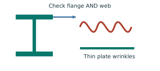
If a plate is too thin it wrinkles locally before it fully yields, so the section cannot reach its full strength. This is different from the whole member buckling.
Comes from (upstream)Plates in compression
Leads to (downstream), Width-to-thickness ratios Stronger steel, stricter limits
What changes itWhere marks are lost
, Width-to-thickness ratios
The larger the ratio, the thinner the plate and the easier it wrinkles. The section table already lists them.
Comes from (upstream)Local buckling: thin plates wrinkle
Leads to (downstream)Class 1 plasticClass 2 compactClass 3 semi-compactClass 4 slender
What changes it
Stronger steel, stricter limits
. Stronger steel must reach a higher stress before wrinkling, so it needs chunkier plates; the limits are multiplied by to tighten them.
Comes from (upstream)Local buckling: thin plates wrinkle
Leads to (downstream)Class 1 plasticClass 2 compactClass 3 semi-compactClass 4 slender
Result
Class 1 plastic
Reaches the full plastic moment with enough rotation to form a plastic hinge. I-section flange , web .
Comes from (upstream), Width-to-thickness ratios Stronger steel, stricter limits
Leads to (downstream)The worst plate decides
Result
Class 2 compact
Reaches the full plastic moment but with limited rotation. Flange within , web within .
Comes from (upstream), Width-to-thickness ratios Stronger steel, stricter limits
Leads to (downstream)The worst plate decides
Result
Class 3 semi-compact
Only reaches the elastic moment (first yield at the edge); it wrinkles before the plastic moment. Flange within , web within .
Comes from (upstream), Width-to-thickness ratios Stronger steel, stricter limits
Leads to (downstream)The worst plate decides
Result
Class 4 slender
Wrinkles before yielding; effective (reduced) properties are needed. The usual exam UB/UC sections are never Class 4.
Comes from (upstream), Width-to-thickness ratios Stronger steel, stricter limits
Leads to (downstream)The worst plate decides
How design deals with itWhere marks are lost
The worst plate decides
Classify the flange and the web separately and take the higher (worse) class. E.g. flange Class 2, web Class 3 → Class 3.
Comes from (upstream)Class 1 plasticClass 2 compactClass 3 semi-compactClass 4 slender
Leads to (downstream)Decides which moment resistance
How design deals with it
Decides which moment resistance
Class 1 or 2 → ; Class 3 → ; Class 4 → effective section. The LTB also depends on the class. Worked numbers: classification map.
Comes from (upstream)The worst plate decides
Leads to (downstream)Theory: purpose of classification
Exam answer
Theory: purpose of classification
One line of purpose (width-to-thickness limits decide whether local buckling stops the section reaching its yield or plastic resistance), then one line for each of the four classes.
Comes from (upstream)Decides which moment resistance
Leads to (downstream)— (the last step)
Tour steps
1. Thin plates in compression wrinkle
A section is made of plates; a thin plate in compression wrinkles locally (local buckling).
In this stepPlates in compressionLocal buckling: thin plates wrinkle
2. What makes it wrinkle more easily?
A larger width-to-thickness ratio; and stronger steel tightens the limits ().
In this step, Width-to-thickness ratios Stronger steel, stricter limits
3. The four classes
From “can form a plastic hinge” to “wrinkles before yield”, each class is worse than the one before.
In this stepClass 1 plasticClass 2 compactClass 3 semi-compactClass 4 slender
4. The whole section takes the worst
Compare flange and web separately and take the worse; that decides between and .
In this stepThe worst plate decidesDecides which moment resistance
5. The theory answer
One line of purpose + one line per class.
In this stepTheory: purpose of classification
Four types of structural analysis Background
Other possible topics Background
Fatigue
Repeated changes of stress (e.g. crane girders, bridges) slowly grow small cracks until the member breaks, even though each load on its own is small.
Brittle fracture
Steel cracks suddenly with little visible deformation. Low temperature, thick plates, welding, stress concentrations and rapid loading increase the risk.
Simple vs continuous construction
Simple design treats beam-to-column joints as pins that carry no moment; bracing or a core resists sideways loads. Continuous design uses joints stiff enough to pass moments between members.
Robustness
Local damage (e.g. a column hit by a vehicle) must not cause a disproportionately large collapse. Measures: ties, alternative load paths, stronger key elements.