Worked Example

960 kN test question: four checks (Four Checks)

Task: Complete the four test calculations using the taught method; the lecturer gives no complete solution in class.

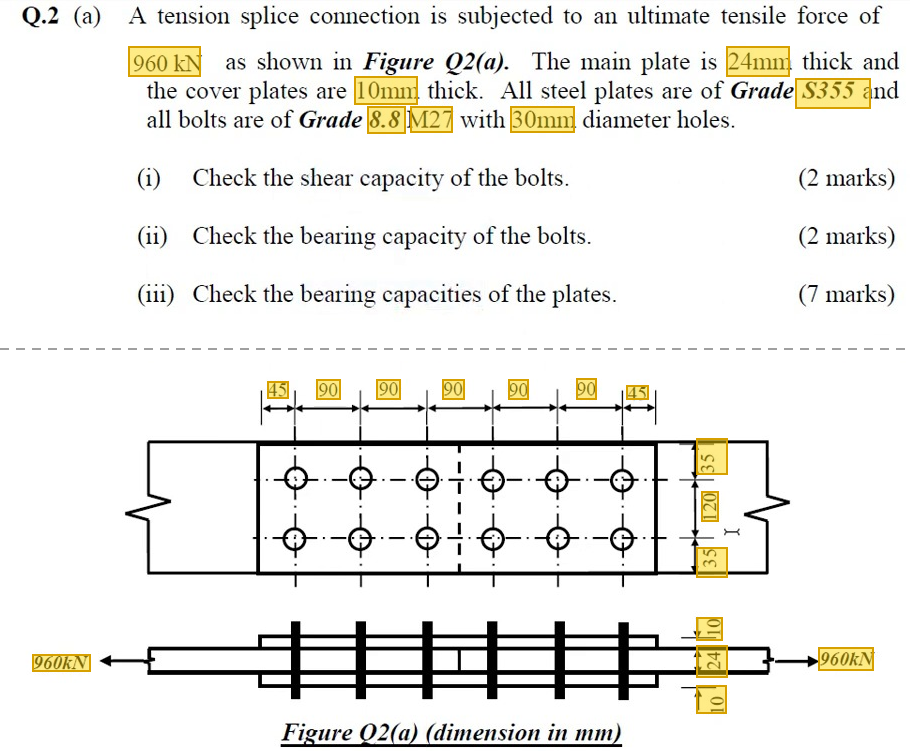
Original question · 7 November · ▶ 01:00:05 (Class test Q.2(a))
Original question with the given values boxed
Yellow boxes: values the question gives, the same values marked yellow in the Given table below.

The question in short: Two 24 mm main plates are joined by two 10 mm cover plates with 6 M27 bolts in each half of the joint. The ultimate pull is 960 kN. Complete four checks: bolt shear, bolt bearing, plate bearing, and tension in the plates.

What differs from the previous example of this type: Same type as the earlier double-cover splice, but here the two covers together are thinner than the main plate. So bearing and tension in the covers must also be checked item by item.

GivenValue and Unit
ProblemUltimate tension 960 kN; main plate 24 mm; two 10 mm covers; S355
Bolts and holesGrade 8.8 M27, As=459 mm2\htmlClass{read}{A_s=459\ \mathrm{mm^{2}}}; 30 mm holes; six bolts per half-joint
GeometryPlate width 35 + 120 + 35 = 190 mm; pitch along the force 90 mm; end distance 45 mm; two holes across
Course table valueskbs=1.0\htmlClass{read}{k_{bs}=1.0}; ps=375\htmlClass{read}{p_s=375}, pbb=1000\htmlClass{read}{p_{bb}=1000}, pbs=550\htmlClass{read}{p_{bs}=550}, Us=510\htmlClass{read}{U_s=510}, Ub=800 N/mm2\htmlClass{read}{U_b=800\ \mathrm{N/mm^{2}}}; Ke=1.1\htmlClass{read}{K_e=1.1}

Yellow: values given in the question. The same values are marked where they are substituted in the steps below.
Orange box: values read directly from the Data File, the same values boxed orange in the lookup screenshots. A value interpolated between two table rows is a calculation, so it has no box.

Double-cover splice: side viewEach half transfers the full axial force; each bolt has two shear planes
Supplementary schematic for understanding; not to scale.

Solution Route: Half-joint demand→double-shear bolts→bolt bearing PbbP_{bb}→main/cover bearing→net-section tension in both plate types.

Interactive 3D model · drag to turn

This browser cannot show the 3D model.

The same type as the 750 kN splice: each M27 bolt has two shear planes. The two 10 mm covers total 20 mm, thinner than the 24 mm main plate, so bolt bearing is governed by the covers; each cover carries half the force.Yellow: values given in the question; orange box: values read from the Data File; white: calculated results; red arrows: forces.
Load path · the stations the force passes through, in order

The same path as the 750 kN splice: main plate → bolts → two cover plates → bolts → main plate. Here the two covers total 20 mm, thinner than the 24 mm main plate, so the cover checks come closer to the limit.

  1. Ultimate tension
    960 kN; six bolts per half, 160 kN each
    Step 1
  2. Main plate in tension (net section)
    Demand 960 kNCapacity 1184.04 kN
    Utilisation 0.81
    Step 8–10
  3. Bearing on the main plate
    Demand 160 kNCapacity 297 kNper bolt
    Utilisation 0.54
    Step 4–5
  4. Bolts in double shear
    Demand 160 kNCapacity 344.25 kNper bolt
    Utilisation 0.46
    Step 2
  5. Bearing on each cover plate
    Demand 80 kNCapacity 123.75 kNper cover, per bolt
    Utilisation 0.65
    Step 6–7
  6. Each cover plate in tension (net section)
    Demand 480 kNCapacity 507.65 kNper cover
    Utilisation 0.95 · closest to the limit
    Step 11–12
Red frame: the station closest to its limit. Each station links to the step that calculates it. Press “Show on the 3D model” to light up that part of the model above; press again to clear.
  1. Step 1 · Demand in each half-joint

    Why this step: The pull goes from one main plate through its bolts into the covers, then through the bolts of the other half into the other main plate. This step finds the force each bolt must pass on.

    Each half transfers the full 960 kN. The halves act in series; do not divide by twelve across both.

    New symbols in this step
    • FF, FsF_s, FTF_T: Total force, shear per bolt and tension per bolt; kN
    • pp, nn: Bolt spacing along the force, mm; number of bolts
    Fbolt=F/n=960/6=160 kNF_{bolt}=F/n={\htmlClass{given}{960}}/{\htmlClass{given}{6}}=160\ \mathrm{kN}

    ▶ The lecturer on this part: 7 November 01:14:29

  2. Step 2 · Double shear

    Why this step: This guards against the bolt being cut at the two faces between the main plate and the covers. With capacity above the demand per bolt, the bolt will not shear off.

    M27 effective area Ae=459 mm2A_e=459\ \mathrm{mm^{2}} comes from the course bolt table; there are two shear planes.

    New symbols in this step
    • PsP_s, PbbP_{bb}, PbsP_{bs}, PtP_t: Shear, bolt bearing, plate bearing and plate tension resistances; kN
    • psp_s, pbbp_{bb}, pbsp_{bs}, pyp_y: Corresponding course design strengths; N/mm²
    Ps=2psAs=2(375)(459)/1000=344.25 kN/bolt>160 kNP_s=2p_sA_s=2({\htmlClass{read}{375}})({\htmlClass{read}{459}})/1000=344.25\ \mathrm{kN/bolt}>160\ \mathrm{kN}
    Ps=2psAs=2(375)(459)/1000=344.25 kN/bolt>160 kN\begin{aligned}P_s&=2p_sA_s\\&=2({\htmlClass{read}{375}})({\htmlClass{read}{459}})/1000\\&=344.25\ \mathrm{kN/bolt}\\&>160\ \mathrm{kN}\end{aligned}

    Units: psp_s in N/mm² times AsA_s in mm² gives N; dividing by 1000 gives kN.

    Data file lookup · Data Page 4 · Bolt tables
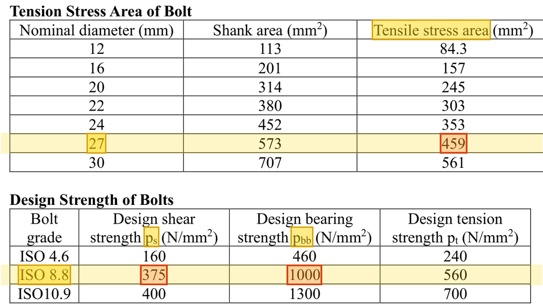
    The M27 row gives tensile stress area As = 459 mm²; the Grade 8.8 row gives ps = 375 N/mm² and pbb = 1000 N/mm².
    The M27 row gives tensile stress area As=459 mm2A_s=459\ \mathrm{mm^{2}}; the Grade 8.8 row gives ps=375 N/mm2p_s=375\ \mathrm{N/mm^{2}} and pbb=1000 N/mm2p_{bb}=1000\ \mathrm{N/mm^{2}}.Yellow: given parameter, row or columnOrange: value read from the table, boxed orange in the text too

    ▶ The lecturer on this part: 7 November 00:59:57

  3. Step 3 · Bolt bearing

    Why this step: The same bolt presses on the main plate one way and on the two covers the other way. The side with less contact thickness is where the bolt is more easily crushed.

    Compare 24 mm main-plate thickness with combined covers of 20 mm; the latter governs.

    New symbols in this step
    • dd, d0d_0, ee, lel_e: Bolt diameter, hole diameter, end distance along force and clear hole spacing; mm
    Pbb,main=dtmainpbb=27(24)(1000)/1000=648 kNPbb,covers=d(2tcover)pbb=27(2×10)(1000)/1000=540 kN/bolt\begin{aligned}P_{bb,main}&=dt_{main}p_{bb}={\htmlClass{given}{27}}({\htmlClass{given}{24}})({\htmlClass{read}{1000}})/1000=648\ \mathrm{kN}\\P_{bb,covers}&=d(2t_{cover})p_{bb}={\htmlClass{given}{27}}(2\times{\htmlClass{given}{10}})({\htmlClass{read}{1000}})/1000=540\ \mathrm{kN/bolt}\end{aligned}
    Pbb,main=dtmainpbb=27(24)(1000)/1000=648 kNPbb,covers=d(2tcover)pbb=27(2×10)(1000)/1000=540 kN/bolt\begin{aligned}P_{bb,main}&=dt_{main}p_{bb}\\&={\htmlClass{given}{27}}({\htmlClass{given}{24}})({\htmlClass{read}{1000}})/1000\\&=648\ \mathrm{kN}\\P_{bb,covers}&=d(2t_{cover})p_{bb}\\&={\htmlClass{given}{27}}(2\times{\htmlClass{given}{10}})({\htmlClass{read}{1000}})/1000\\&=540\ \mathrm{kN/bolt}\end{aligned}

    Units: dd and the plate thickness are in mm and pbbp_{bb} is in N/mm², so each product is in N; both lines divide by 1000 to give kN.

  4. Step 4 · Clear distance between holes

    Why this step: Only after deducting the hole do we get the real steel between two holes. This length goes into the bearing calculations for both the main plate and the covers.

    Subtract 30 mm hole diameter d0d_0 from 90 mm longitudinal pitch. Standard holes use kbs=1k_{bs}=1.

    le=p−d0=90−30=60 mml_e=p-d_0={\htmlClass{given}{90}}-{\htmlClass{given}{30}}=60\ \mathrm{mm}
  5. Step 5 · Four main-plate bearing candidates

    Why this step: This guards against the main plate being crushed at the hole or the steel behind the hole being pushed out. The smallest of the four values is the bearing capacity of the main plate.

    Substitute 24 mm main-plate thickness and 45 mm end distance ee in each expression; convert N to kN.

    New symbols in this step
    • kbsk_{bs}, KeK_e: Hole-type and effective-area factors; dimensionless
    kbsdtppbs=1.0(27)(24)(550)/1000=356.40.5kbsetppbs=0.5(1.0)(45)(24)(550)/1000=2971.5letpUs=1.5(60)(24)(510)/1000=1101.62.0dtpUb=2.0(27)(24)(800)/1000=1036.8Pbs,main=min⁡(356.4, 297, 1101.6, 1036.8)=297 kN/bolt\begin{aligned}k_{bs}dt_pp_{bs}&={\htmlClass{read}{1.0}}({\htmlClass{given}{27}})({\htmlClass{given}{24}})({\htmlClass{read}{550}})/1000=356.4\\0.5k_{bs}et_pp_{bs}&=0.5({\htmlClass{read}{1.0}})({\htmlClass{given}{45}})({\htmlClass{given}{24}})({\htmlClass{read}{550}})/1000=297\\1.5l_et_pU_s&=1.5(60)({\htmlClass{given}{24}})({\htmlClass{read}{510}})/1000=1101.6\\2.0dt_pU_b&=2.0({\htmlClass{given}{27}})({\htmlClass{given}{24}})({\htmlClass{read}{800}})/1000=1036.8\\P_{bs,main}&=\min(356.4,\ 297,\ 1101.6,\ 1036.8)=297\ \mathrm{kN/bolt}\end{aligned}
    kbsdtppbs=1.0(27)(24)(550)/1000=356.40.5kbsetppbs=0.5(1.0)(45)(24)(550)/1000=2971.5letpUs=1.5(60)(24)(510)/1000=1101.62.0dtpUb=2.0(27)(24)(800)/1000=1036.8Pbs,main=min⁡(356.4, 297, 1101.6, 1036.8)=297 kN/bolt\begin{aligned}k_{bs}dt_pp_{bs}&={\htmlClass{read}{1.0}}({\htmlClass{given}{27}})({\htmlClass{given}{24}})({\htmlClass{read}{550}})/1000\\&=356.4\\0.5k_{bs}et_pp_{bs}&=0.5({\htmlClass{read}{1.0}})({\htmlClass{given}{45}})({\htmlClass{given}{24}})({\htmlClass{read}{550}})/1000\\&=297\\1.5l_et_pU_s&=1.5(60)({\htmlClass{given}{24}})({\htmlClass{read}{510}})/1000\\&=1101.6\\2.0dt_pU_b&=2.0({\htmlClass{given}{27}})({\htmlClass{given}{24}})({\htmlClass{read}{800}})/1000\\&=1036.8\\P_{bs,main}&=\min(356.4,\ 297,\ 1101.6,\ 1036.8)\\&=297\ \mathrm{kN/bolt}\end{aligned}

    Where the numbers come from: 6060 from Step 4.

    Units: dd, ee, lel_e and tpt_p are in mm; pbsp_{bs}, UsU_s and UbU_b are in N/mm². Each product is in N, and dividing by 1000 gives kN.

    Data file lookup · Data Page 4 · Bearing of connected part
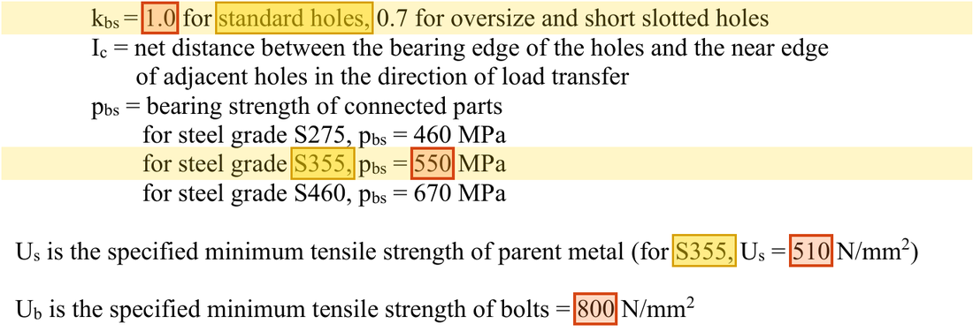
    Standard holes give kbs = 1.0. For S355 plate the bearing strength is pbs = 550 N/mm² and Us = 510 N/mm²; for the bolt Ub = 800 N/mm².
    Standard holes give kbs=1.0k_{bs}=1.0. For S355 plate the bearing strength is pbs=550 N/mm2p_{bs}=550\ \mathrm{N/mm^{2}} and Us=510 N/mm2U_s=510\ \mathrm{N/mm^{2}}; for the bolt Ub=800 N/mm2U_b=800\ \mathrm{N/mm^{2}}.Yellow: given parameter, row or columnOrange: value read from the table, boxed orange in the text too
    Load path · Four limits on plate bearing
    Bolt pushes towards the plate end →d = 27Hole wall crusheskbsdtppbs​= 356.4 kNe = 45End tear-out0.5kbsetppbs​= 297 kNGoverns (smallest)le​ = 60Tear between holes1.5letpUs​= 1101.6 kNUb​Bolt strength cap2.0dtpUb​= 1036.8 kNDemand per bolt on the main plate 160 kN < Pbs​ = 297 kN
    The bolt presses on the hole wall, and the plate can fail in four ways: the hole wall crushes, the bolt tears out through the plate end, the plate tears between two holes, and there is a cap set by the bolt strength. The smallest of the four values is used (red frame).

    ▶ The lecturer on this part: 7 November 00:59:57

  6. Step 6 · Bearing per cover plate

    Why this step: Each cover is much thinner than the main plate, so its hole wall has less contact area and crushes more easily. The demand must also be the force on one cover.

    Each 10 mm cover carries 80 kN per bolt. The four candidates are 148.5, 123.75, 459 and 432.

    kbsdtppbs=1.0(27)(10)(550)/1000=148.50.5kbsetppbs=0.5(1.0)(45)(10)(550)/1000=123.751.5letpUs=1.5(60)(10)(510)/1000=4592.0dtpUb=2.0(27)(10)(800)/1000=432Pbs,one=min⁡(148.5, 123.75, 459, 432)=123.75 kN>160/2=80 kN\begin{aligned}k_{bs}dt_pp_{bs}&={\htmlClass{read}{1.0}}({\htmlClass{given}{27}})({\htmlClass{given}{10}})({\htmlClass{read}{550}})/1000=148.5\\0.5k_{bs}et_pp_{bs}&=0.5({\htmlClass{read}{1.0}})({\htmlClass{given}{45}})({\htmlClass{given}{10}})({\htmlClass{read}{550}})/1000=123.75\\1.5l_et_pU_s&=1.5(60)({\htmlClass{given}{10}})({\htmlClass{read}{510}})/1000=459\\2.0dt_pU_b&=2.0({\htmlClass{given}{27}})({\htmlClass{given}{10}})({\htmlClass{read}{800}})/1000=432\\P_{bs,one}&=\min(148.5,\ 123.75,\ 459,\ 432)=123.75\ \mathrm{kN}>160/2=80\ \mathrm{kN}\end{aligned}
    kbsdtppbs=1.0(27)(10)(550)/1000=148.50.5kbsetppbs=0.5(1.0)(45)(10)(550)/1000=123.751.5letpUs=1.5(60)(10)(510)/1000=4592.0dtpUb=2.0(27)(10)(800)/1000=432Pbs,one=min⁡(148.5, 123.75, 459, 432)=123.75 kN>160/2=80 kN\begin{aligned}k_{bs}dt_pp_{bs}&={\htmlClass{read}{1.0}}({\htmlClass{given}{27}})({\htmlClass{given}{10}})({\htmlClass{read}{550}})/1000\\&=148.5\\0.5k_{bs}et_pp_{bs}&=0.5({\htmlClass{read}{1.0}})({\htmlClass{given}{45}})({\htmlClass{given}{10}})({\htmlClass{read}{550}})/1000\\&=123.75\\1.5l_et_pU_s&=1.5(60)({\htmlClass{given}{10}})({\htmlClass{read}{510}})/1000\\&=459\\2.0dt_pU_b&=2.0({\htmlClass{given}{27}})({\htmlClass{given}{10}})({\htmlClass{read}{800}})/1000\\&=432\\P_{bs,one}&=\min(148.5,\ 123.75,\ 459,\ 432)\\&=123.75\ \mathrm{kN}\\&>160/2\\&=80\ \mathrm{kN}\end{aligned}

    Where the numbers come from: 6060 from Step 4; 160160 from Step 1.

    Units: The lengths and tpt_p are in mm; pbsp_{bs}, UsU_s and UbU_b are in N/mm². Each product is in N; dividing by 1000 gives kN, ready to compare with the demand on one cover.

  7. Step 7 · Equivalent combined-cover comparison

    Why this step: Capacity and demand must cover the same thing: one cover against the share of one cover, or both covers against the whole bolt force. Either way gives the same conclusion.

    If using combined resistance 247.5, use the total per-bolt demand 160 as well.

    2Pbs,one=2(123.75)=247.5 kN/bolt>160 kN2P_{bs,one}=2(123.75)=247.5\ \mathrm{kN/bolt}>160\ \mathrm{kN}
    2Pbs,one=2(123.75)=247.5 kN/bolt>160 kN\begin{aligned}2P_{bs,one}&=2(123.75)\\&=247.5\ \mathrm{kN/bolt}\\&>160\ \mathrm{kN}\end{aligned}

    Where the numbers come from: 123.75123.75 from Step 6.

  8. Step 8 · Main-plate net section

    Why this step: This guards against the main plate being pulled apart along a row of holes. The steel removed is set by the hole size, because the hole is larger than the bolt.

    The straight section crosses two holes: deduct 2×30, not 2×27.

    An,main=(b−2d0)t=(190−2×30)(24)=3120 mm2A_{n,main}=(b-2d_0)t=({\htmlClass{given}{190}}-2\times{\htmlClass{given}{30}})({\htmlClass{given}{24}})=3120\ \mathrm{mm^2}
    An,main=(b−2d0)t=(190−2×30)(24)=3120 mm2\begin{aligned}A_{n,main}&=(b-2d_0)t\\&=({\htmlClass{given}{190}}-2\times{\htmlClass{given}{30}})({\htmlClass{given}{24}})\\&=3120\ \mathrm{mm^2}\end{aligned}

    ▶ The lecturer on this part: 7 November 01:14:29

  9. Step 9 · Main-plate effective area and strength

    Why this step: This turns the area after deducting holes into the area used for tension capacity. Multiplying it by the design strength in the next step gives the tension capacity of the main plate.

    Apply KeK_e to net area AnA_n without exceeding gross area AgA_g. For 24 mm, the course uses py=345p_y=345.

    New symbols in this step
    • AsA_s, AgA_g, AnA_n, AeA_e: Bolt effective shear area and gross/net/effective plate areas; mm²
    Ae=min⁡(KeAn, Ag)=min⁡(1.1(3120), 190(24))=3432 mm2A_e=\min(K_eA_n,\ A_g)=\min({\htmlClass{read}{1.1}}(3120),\ {\htmlClass{given}{190}}({\htmlClass{given}{24}}))=3432\ \mathrm{mm^2}
    Ae=min⁡(KeAn, Ag)=min⁡(1.1(3120), 190(24))=3432 mm2\begin{aligned}A_e&=\min(K_eA_n,\ A_g)\\&=\min({\htmlClass{read}{1.1}}(3120),\ {\htmlClass{given}{190}}({\htmlClass{given}{24}}))\\&=3432\ \mathrm{mm^2}\end{aligned}

    Where the numbers come from: 31203120 from Step 8.

    Data file lookup · Data Page 2 · Tension members

    Ke = 1.1 for S355.
    Ke=1.1K_e=1.1 for S355.Yellow: given parameter, row or columnOrange: value read from the table, boxed orange in the text too
    Data file lookup · Data Page 1 · Design strength pyp_y
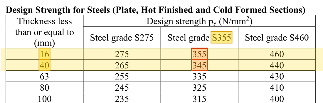
    Cover plate 10 mm thick: the T ≤ 16 mm row, S355 column gives py = 355 N/mm²; main plate 24 mm thick: the T ≤ 40 mm row, S355 column gives py = 345 N/mm².
    Cover plate 10 mm thick: the T≤16 mmT\le16\ \mathrm{mm} row, S355 column gives py=355 N/mm2p_y=355\ \mathrm{N/mm^{2}}; main plate 24 mm thick: the T≤40 mmT\le40\ \mathrm{mm} row, S355 column gives py=345 N/mm2p_y=345\ \mathrm{N/mm^{2}}. How the grade and thickness choose this row →Yellow: given parameter, row or columnOrange: value read from the table, boxed orange in the text too
  10. Step 10 · Main-plate tension resistance

    Why this step: The main plate alone carries the whole pull, so its capacity is compared with the total pull, not with the force per bolt.

    Compare with the full connection force of 960 kN.

    Pt,main=pyAe=345(3432)/1000=1184.04 kN>960 kNP_{t,main}=p_yA_e={\htmlClass{read}{345}}(3432)/1000=1184.04\ \mathrm{kN}>{\htmlClass{given}{960}}\ \mathrm{kN}
    Pt,main=pyAe=345(3432)/1000=1184.04 kN>960 kN\begin{aligned}P_{t,main}&=p_yA_e\\&={\htmlClass{read}{345}}(3432)/1000\\&=1184.04\ \mathrm{kN}\\&>{\htmlClass{given}{960}}\ \mathrm{kN}\end{aligned}

    Where the numbers come from: 34323432 from Step 9.

    Units: pyp_y is in N/mm² and AeA_e is in mm², so the product is in N; dividing by 1000 gives kN.

  11. Step 11 · Tension in both covers

    Why this step: In the middle of the joint the pull is carried entirely by the two covers. Together they are thinner than the main plate, so they are more likely to break at the holes.

    Each has An=1300A_n=1300 and Ae=1430A_e=1430. At 10 mm, py=355p_y=355; each carries 480 kN.

    An,one=(b−2d0)t=(190−2×30)(10)=1300 mm2Ae=KeAn=1.1(1300)=1430 mm2Pt,one=pyAe=355(1430)/1000=507.65 kN>960/2=480 kN\begin{aligned}A_{n,one}&=(b-2d_0)t=({\htmlClass{given}{190}}-2\times{\htmlClass{given}{30}})({\htmlClass{given}{10}})=1300\ \mathrm{mm^2}\\A_e&=K_eA_n={\htmlClass{read}{1.1}}(1300)=1430\ \mathrm{mm^2}\\P_{t,one}&=p_yA_e={\htmlClass{read}{355}}(1430)/1000=507.65\ \mathrm{kN}>{\htmlClass{given}{960}}/2=480\ \mathrm{kN}\end{aligned}
    An,one=(b−2d0)t=(190−2×30)(10)=1300 mm2Ae=KeAn=1.1(1300)=1430 mm2Pt,one=pyAe=355(1430)/1000=507.65 kN>960/2=480 kN\begin{aligned}A_{n,one}&=(b-2d_0)t\\&=({\htmlClass{given}{190}}-2\times{\htmlClass{given}{30}})({\htmlClass{given}{10}})\\&=1300\ \mathrm{mm^2}\\A_e&=K_eA_n={\htmlClass{read}{1.1}}(1300)=1430\ \mathrm{mm^2}\\P_{t,one}&=p_yA_e\\&={\htmlClass{read}{355}}(1430)/1000\\&=507.65\ \mathrm{kN}\\&>{\htmlClass{given}{960}}/2\\&=480\ \mathrm{kN}\end{aligned}

    Units: pyp_y is in N/mm² and the AeA_e of one cover is in mm², so the product is in N; dividing by 1000 gives kN.

    ▶ The lecturer on this part: 7 November 01:14:29

  12. Step 12 · Identify the closest margin

    Why this step: The item with the highest utilisation reaches its limit first. It shows that if the pull grew, the covers breaking at the holes would be the first failure.

    Combined cover tension resistance PtP_t is 1015.3 kN, closest to 960 among these four checks, with utilisation about 0.946. Other hole-position and complete-connection details still need checking.

    ηcovers=F/(2Pt,one)=960/1015.3≈0.946\eta_{covers}=F/(2P_{t,one})={\htmlClass{given}{960}}/1015.3\approx0.946
    ηcovers=F/(2Pt,one)=960/1015.3≈0.946\begin{aligned}\eta_{covers}&=F/(2P_{t,one})\\&={\htmlClass{given}{960}}/1015.3\\&\approx0.946\end{aligned}
Conclusion

With the stated geometry and course table values, all four capacities are adequate. Do not transfer the replayed 750 kN example's thicknesses, holes or 818.2 kN result here.

All the symbols of this example

SymbolsMeaning and Units
FF, FsF_s, FTF_TTotal force, shear per bolt and tension per bolt; kN
PsP_s, PbbP_{bb}, PbsP_{bs}, PtP_tShear, bolt bearing, plate bearing and plate tension resistances; kN
dd, d0d_0, ee, lel_eBolt diameter, hole diameter, end distance along force and clear hole spacing; mm
AsA_s, AgA_g, AnA_n, AeA_eBolt effective shear area and gross/net/effective plate areas; mm²
psp_s, pbbp_{bb}, pbsp_{bs}, pyp_yCorresponding course design strengths; N/mm²
UsU_s, UbU_bPlate and bolt ultimate tensile strengths; N/mm²
kbsk_{bs}, KeK_eHole-type and effective-area factors; dimensionless
pp, nnBolt spacing along the force, mm; number of bolts

Video positions: 7 November 00:15:00 · 7 November 00:20:00 · 7 November 01:15:00 · 24 October 02:35:00

↑ Top